The Project Gutenberg EBook of Irrigation Works, by E. S. Bellasis

This eBook is for the use of anyone anywhere in the United States and most
other parts of the world at no cost and with almost no restrictions
whatsoever.  You may copy it, give it away or re-use it under the terms of
the Project Gutenberg License included with this eBook or online at
www.gutenberg.org.  If you are not located in the United States, you'll have
to check the laws of the country where you are located before using this ebook.


Title: Irrigation Works
       The Principles on which their Design and Working should be Based...

Author: E. S. Bellasis

Release Date: December 3, 2017 [EBook #56113]

Language: English

Character set encoding: ISO-8859-1

*** START OF THIS PROJECT GUTENBERG EBOOK IRRIGATION WORKS ***


Produced by Chris Curnow, Harry Lame
and the Online Distributed Proofreading Team at
http://www.pgdp.net (This file was produced from images
generously made available by The Internet Archive)
Please see the Transcriber’s Notes at the end of this text.
The cover image has been created for this e-text, and is placed in the public domain.
By the Same Author
RIVER AND CANAL ENGINEERING. The Characteristics of Open Flowing Streams, and the principles and methods to be followed in dealing with them. 72 illustrations, x + 220 pp., 8vo (1913).
8/6 net.
PUNJAB RIVERS AND WORKS. Second Edition. 47 illustrations, viii + 64 pp., folio (1912).
8/- net.
HYDRAULICS WITH WORKING TABLES. Second Edition. 160 illustrations, xii + 311 pp., 8vo (1911).
12/- net.
THE SUCTION CAUSED BY SHIPS. Explained in Popular Language. 2 plates, 26 pp., 8vo, sewed (1912).
1/- net.
E. & F. N. SPON, LTD., LONDON

BRIDGE ON AN INDIAN CANAL.
Frontispiece.
IRRIGATION WORKS
THE PRINCIPLES ON WHICH THEIR DESIGN
AND WORKING SHOULD BE BASED, WITH
SPECIAL DETAILS RELATING TO
INDIAN CANALS
AND SOME PROPOSED IMPROVEMENTS
BY
E. S. BELLASIS, M.Inst.C.E.
RECENTLY SUPERINTENDING ENGINEER IN THE IRRIGATION BRANCH OF THE PUBLIC WORKS DEPARTMENT OF INDIA
37 Illustrations

London
E. & F. N. SPON, Ltd., 57 HAYMARKET, S.W.
New York
SPON & CHAMBERLAIN, 123 LIBERTY STREET
1913
[v]
| PAGE | ||
|---|---|---|
| Preface | vii | |
| CHAPTER I INTRODUCTION |
||
| ARTICLE | ||
| 1. | Preliminary Remarks | 1 |
| 2. | General Principles of Canal Design | 2 |
| 3. | Information concerning Canals | 11 |
| 4. | Losses of Water | 16 |
| 5. | Duty of Water | 21 |
| 6. | Sketch of a Project | 26 |
| CHAPTER II THE DESIGNING OF A CANAL |
||
| 1. | Headworks | 30 |
| 2. | The Contour Map | 36 |
| 3. | Alignments and Discharges | 37 |
| 4. | Remarks on Distributaries | 45 |
| 5. | Design of Canal and Branches | 47 |
| 6. | Banks and Roads | 53 |
| 7. | Trial Lines | 58 |
| 8. | Final Line and Estimate | 59 |
| 9. | Design of a Distributary | 60 |
| 10. | Best System of Distributaries | 71 |
| 11. | Outlets | 76 |
| 12. | Masonry Works | 80 |
| 13. | Pitching | 90 |
| 14. | Miscellaneous Items | 93 |
| [vi]CHAPTER III THE WORKING OF A CANAL |
||
| 1. | Preliminary Remarks | 96 |
| 2. | Gauges and Regulators | 103 |
| 3. | Gauge Readings and Discharges | 106 |
| 4. | Registers of Irrigation and Outlets | 113 |
| 5. | Distribution of Supply | 118 |
| 6. | Extensions and Remodellings | 127 |
| 7. | Remodelling of Outlets | 131 |
| 8. | Miscellaneous Items | 137 |
| CHAPTER IV THE PUNJAB TRIPLE CANAL PROJECT |
||
| 1. | General Description | 144 |
| 2. | Areas and Discharges | 147 |
| 3. | Remarks | 156 |
| CHAPTER V PROPOSED IMPROVEMENTS IN IRRIGATION CANALS |
||
| 1. | Preliminary Remarks | 158 |
| 2. | Reduction of Losses in the Channels | 159 |
| 3. | Modules | 162 |
| APPENDICES | ||
| A. | Divide Wall on Lower Chenab Canal | 169 |
| B. | Specification for Maintenance of Channels | 171 |
| C. | Specification for Maintenance of Masonry Works | 174 |
| D. | Watching and Protecting Banks and Embankments | 175 |
| E. | Specification for Bushing | 178 |
| F. | Escapes | 180 |
| G. | Gauges | 183 |
| H. | Gibb’s Module | 186 |
| K. | Kennedy’s Gauge Outlet | 193 |
| Index | 196 | |
[vii]
When River and Canal Engineering was written it was decided to omit Irrigation works and to deal with them separately because the subject interests chiefly specialists.
The present book deals with the principles which govern the design and management of Irrigation works, and it discusses the Canals of Northern India—the largest and best in the world—in detail.
Some years ago a number of rules for designing distributaries were framed, at the request of the Punjab Government, by the late Colonel S. L. Jacob, C.I.E., R.E., and comments on these rules were obtained from many experienced engineers and recorded. The author has had the advantage of reading all these opinions. Generally the weight of opinion on any point agrees with what most experienced engineers would suggest, and direct conflicts of opinion scarcely occur. Important papers have been printed by the Punjab Irrigation Branch on Losses of Water and the Design of Distributaries, on the great Triple Canal Project, on Gibb’s Module, on Kennedy’s Gauge Outlet, and on the Lining of Watercourses. These papers are not always accessible to engineers, and the chief points of interest in them are not, in most cases, discernible at a glance. Such points have been extracted and are given in this book.
E. S. B.
Cheltenham, May 20th, 1913.
[1]
IRRIGATION WORKS.
—The largest irrigation canals are fed from perennial rivers. When the canal flows throughout the year it is called a “Perennial Canal.” Chief among these are the canals of India and particularly those of Northern India, some of which have bed widths ranging up to 300 feet, depths of water up to 11 feet and discharges up to 10,000 c. ft. per second. Other large canals as for instance many of those in Scinde, Egypt and the Punjab, though fed from perennial rivers, flow only when the rivers are high. These are called “Inundation Canals.” Many canals, generally of moderate or small size, in other countries and notably in the Western States of America, in Italy, Spain, France and South Africa, are fed from rivers and great numbers of small canals from reservoirs in which streams or rain-water have been impounded. Sometimes water for irrigation is pumped from wells and conveyed in small canals. In Australia a good deal of irrigation is effected from artesian wells. Irrigation works on a considerable scale are being undertaken in Mexico and the Argentine. In this book, irrigation works of various countries are referred to and to some extent described, but the perennial canal of Northern India, with its distributaries, is the type taken as a basis for the description of the principles and methods which should be adopted in the design, working and improvement of irrigation channels and it is to be[2] understood that such a canal is being referred to where the context does not indicate the contrary. Any reader who is concerned with irrigation in some other part of the world will be able to judge for himself how far these principles and methods require modification. The branches and distributaries—all of which are dealt with—of a large perennial canal cover all possible sizes.
Chapter II. of this book deals with the design of canals and Chapter III. with the working of canals but as the two subjects are to some extent interdependent, they will both be dealt with in a preliminary manner in the remaining articles of the present Chapter. Chapter IV. describes the Punjab Triple Canal Project.[1] Chapter V. deals with certain proposed improvements in the working of canals.
[1] The latest example of canal design.
—The head of a canal has to be so high up the river that, when the canal is suitably graded, the water level will come out high enough to irrigate the tract of land concerned. If a river has a general slope of a foot per mile and if the adjoining country has the same slope and is a foot higher than the water level of the river, and if a canal is made at a very acute angle with the river, with a slope of half a foot per mile, the water level about two miles from the canal head will be level with the ground.
The headworks of the canal consist of a weir—which may be provided with sluices—across the river, and a head “regulator,” provided with gates, for the canal. There are however many canals, those for instance of the inundation canal class, which have no works in the river and these may go dry when the river is low.[3] They usually have a regulator to prevent too much water from going down the canal during floods. If a canal is fed from a reservoir the headworks consist simply of a sluice or sluices.
A canal must be so designed as to bring the water to within reasonable distance of every part of the area to be irrigated. Unless the area is small or narrow the canal must have “branches” and “distributaries.” A general sketch of a large canal is given in Fig. 1. On a large canal, irrigation is not usually done directly from the canal and branches. It is all done from the distributaries.
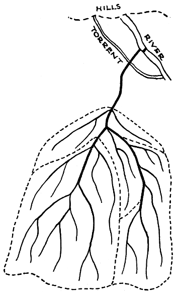
Fig. 1.
[4]
From each distributary “watercourses” take off at intervals and convey the water to the fields. A small canal, say one whose length is not more than 15 miles or whose discharge is not more than 100 c. feet per second, may be regarded as a distributary and the word distributary will be used with this extended meaning.
It is not always the case that the whole tract covered by a system of canal channels is irrigated. In the case of a canal fed from a river, the land near the river is often high or broken and the main canal runs for some distance before it reaches the tract to be irrigated. Again, within this tract there are usually portions of land too high to be irrigated. Those portions of the tract which can be irrigated are called the “commanded area.”
The channels of a large irrigation system should run on high ground. In the case of a distributary, this is necessary in order that the water-courses may run downhill, and since the water in the canal and branches has to flow into the distributaries, the canal and branches must also be in high ground. Another reason for adopting high ground is that all the channels should, as far as possible, keep away from the natural drainage lines of the country and not obstruct them. Also a channel in high ground is cheapest and safest. When a channel is in low ground it must have high banks which are expensive to make and liable to breach. Every tract of country possesses more or less defined ridges and valleys. When the ridges are well defined, the irrigation channels, especially the distributaries, follow them approximately, deviating slightly on one side or the other from the very top of the ridge in order to secure a more[5] direct course. If any part of a ridge is so high as to necessitate deep digging the channel does not necessarily go through it. It may skirt it and return to the crest of the ridge further on, especially if this arrangement shortens the channel or at least does not lengthen it much. A channel also goes off the ridge sometimes when adherence to it would give a crooked line. Of course all the channels—canals, branches and distributaries—have to flow more or less in the direction of the general slope of the tract being dealt with.
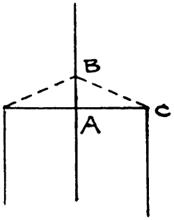
Fig. 2.
The alignments of the channels do not, however, depend exclusively on the physical features of the country. Centrality in the alignment is desirable. It will be shown (Chap. II. Art. 10) that a distributary works most economically when it runs down the centre of the tract which it has to irrigate. It is better to have short watercourses running off from both sides of a distributary than long watercourses from only one side. The same is true of a branch; it should run down the centre of its tract of country. Again the angles at which the channels branch off have to be considered. If branches were taken off very high up the canal and ran parallel to and not far from it, there would be an excessive length of channel. But neither should the branches be so arranged as to form a series of right angles. In the case shown in Fig. 2 the size of the main[6] or central canal would of course be reduced at the point A. By altering the branches to the positions shown in dotted lines their length is not appreciably increased while the length A B is made of the reduced instead of the full size. Moreover the course B C is more direct than BAC and this may be of the greatest importance as regards gaining the necessary command. When a channel bifurcates, the total wet border always increases and there is then a greater loss from absorption. The water is always kept in bulk as long as possible. If the alignment of a branch is somewhat crooked it does not follow that straightening it—supposing the features of the country admit of this—will be desirable. It may increase the length of distributaries taken off near the bends. It will be shown (Chap. II. Art. 10) that a distributary ought, when matters can be so arranged, to irrigate the country for two miles on either side of it, and watercourses should be two or three miles long. A distributary need not therefore extend right up to the boundary of the commanded area but stop two or three miles from it. Generally it is not desirable to prolong a distributary and make it “tail” into another channel (Chap. II. Art. 3). A distributary, like a canal, may give off branches.
None of the rules mentioned in the preceding paragraph are intended to be other than general guides, to be followed as far as the physical features of the country permit, or to assist in deciding between alternative schemes. It may for instance be a question whether to construct one distributary or two, between two nearly parallel branches. The two-mile rule may enable the matter to be decided or it may influence the decision arrived at as to the exact alignments of the branches.[7] The flatter the country and the less marked the ridges the more the alignment can be based on the above rules. Sometimes, as in the low land adjoining a river, the ridges are ill defined or non-existent and the alignment is based entirely on the above rules. The rule as to following high ground need not be adhered to at the tail of any distributary if all the land to be irrigated at the tail is low and if there is a deep drainage line or other feature of the country such as to preclude the possibility of an extension of the distributary. Possible extensions should always be considered. In hilly districts an irrigation canal may have to run in sidelong ground along the side of a valley.
In flat valleys, owing to the land nearest the river having received successive deposits of silt in floods, the ground generally slopes away from the river and a canal can irrigate the low land even if taken off at right angles to the river. But to irrigate the high land near the river and the land where it rises again towards the hills or watershed, a canal taking off higher up the river is necessary. Of course much depends on whether the canal is to irrigate when the river is low or only when it is high, and whether or not there is to be a weir in the river. In Upper Egypt, it is common for a high level canal taking off far upstream, to divide into two branches, one for the land near the river and one for the land towards the watershed, and for both branches to be crossed—by means of syphons—by a low-level canal which irrigates the low ground. Similar arrangements sometimes occur on Indian inundation canals.
Regulators are usually provided at all off-takes of branches. In the case of a channel taking off from[8] another channel many times its own size there is generally only the head regulator of the smaller channel but in other cases there is a regulator in each channel below the bifurcation. Thus, when the number of bifurcating channels is two it is called a double regulator. Regulators, with the “falls”—introduced to flatten the gradients when the slope of the country is too steep—and drainage crossings and the bridges, provided at the principal roads, constitute the chief masonry works on a canal. At a fall, mills are often constructed or the fall may be used for electric power.
Regarding curves and bends in channels, it is explained in River and Canal Engineering that, as regards increased resistance to flow and consequent tendency to silt deposit, curves of fair radius have very little effect, that a curve of a given angle may perhaps have the same effect whether the radius is great or small but that if the radius is large a succession of curves cannot be got into a short length, that a succession of sharp curves in a short length may have great effect, amounting to an increase of N in Kutter’s co-efficient, that a single sharp curve has not much effect, that the chief objection to such a curve is the tendency to erosion of the bank, that at a place where the channel has, in any case, to be protected, as for instance just below a weir or fall, there is no objection to the introduction of a sharp bend and that such bends, in fact right-angled elbows, exist without any evil effects at many regulators when the whole supply is being turned into a branch. It is remarkable that on perennial canals no advantage is ever taken of the last mentioned fact. Cases undoubtedly occur, though somewhat infrequently, in which the[9] most suitable and cheapest arrangement would be to give a canal an abrupt bend at a fall. In order to reduce eddying, the bend need not be an absolute elbow but can be made within the length of the pitching which would be curved instead of straight. This is frequently done on inundation canals, without the slightest drawback, even when there is no fall, the pitching at bridges being utilised. A pitched bend can be made anywhere.
When a river floods the country along its banks as in parts of Egypt and of the Punjab, it is generally necessary to construct marginal embankments before irrigation can be introduced. The canal may take off at a point where flooding does not occur or it may pass through the embankment.[2] If it passes through at a point where flooding occurs, a masonry regulator is constructed to prevent the floods from enlarging the gap and breaking into the country.
[2] For detailed accounts of such embankments and canals see Punjab Rivers and Works (Spon) 1912.
A large canal is provided, so far as is practicable, with “escapes” by means of which surplus water may be let out. Surplus water occurs chiefly after rain. At such times the demand for water may suddenly be reduced and if there were no escapes there would probably be serious breaches of the banks before there was time for the reduction of water, effected at the head of the canal, to take effect lower down. There is usually an escape at some point in the main line, preferably at a point where it divides into branches, and this escape runs back to the river. There may also be escapes near the tails of the longest branches. These escapes may discharge into drainages or into reservoirs formed by running a low embankment round a large area of waste land.
[10]
The drainage of the whole tract irrigated by a canal must be carefully seen to. The subsoil water level of a tract of country is nearly always raised by an irrigation canal. The rise near to a canal or distributary is due to percolation from the channel and is inevitable.[3] The rise at places further away, if it occurs, is due to over-watering or to neglect of drainage. Immense damage has been done by “water-logging” of the soil when irrigation water has been supplied to a tract of flat country and the clearance and improvement of the natural drainages has not been attended to. Any drainages crossed by the banks of the irrigation channels should be provided with syphons or aqueducts or else the drainage diverted into another channel. Very frequently the main line of a canal—whether great or small—in the upper reaches near the hills, has to cross heavy drainage channels or torrents and large and expensive works are required for this.
Near the head of a canal and of every branch and distributary, there is an ordinary gauge which shows the depth of water and is read daily. The gauge near the head of a main canal is generally self-registering.
The principles sketched out in this article are those generally followed in the designs of modern canals. They have by no means been followed in all cases. In some of the older Indian canals both the canal and the distributaries ran in low ground. Water-courses took off direct from the canals, and the irrigation did not generally extend far from the canal. In fact long distributaries were impracticable because they would have run into high ground. The banks of the channels obstructed drainages and caused pestilential swamps.[11] Most canals of this type have been abolished since the advent of British rule and replaced by others properly designed. Some badly designed canals however, mostly of the inundation class, still exist but in very dry tracts where drainages are of little consequence.
—Nearly all canal irrigation is done by “flow,” the water running from the water-courses onto the fields, but a small proportion is done by “lift.” This is done in the case of high pieces of land, the lifting being usually done by pumps or, in the east, by bullocks or by manual labour.
Irrigation generally consists in giving the land a succession of waterings, one previous to ploughing and others after the crop is sown, each watering being of quite moderate depth. On inundation canals in India the waterings for the summer crop are thus effected but for the winter crop the land is deeply soaked during the flood season and is afterwards ploughed and sown. In Upper Egypt this system is emphasised, the water flowing into vast basins, formed by dykes, where it stands for some time and, after depositing its silt, is drained off.
Until recent times the whole of the irrigation of Egypt was basin irrigation. In Lower Egypt the construction of the Nile barrage led to the introduction of canals which take off at a proper level and their working is not restricted to the period when the river is in flood. In Upper Egypt most of the irrigation is still basin irrigation but the canals taking off above the Assiut barrage form a notable exception. By means of the Assouan dam which crosses the Nile, the water during[12] the latter part of the flood season and after the floods are over, i.e. from November to March, is ponded up and a vast reservoir formed and the impounded water is let down the river in May and June.
In some of the older irrigation canals of India the velocity was too high and the channels have since had to be remodelled and the crests of weirs raised or new weirs built. The more recent canals are free from grave defects of this kind but every canal undergoes changes of some kind and finality has never yet been quite attained.
On some Indian irrigation canals made about 30 years ago, great sums of money were wasted in making the canals navigable. There is nothing like enough navigation to pay for the extra cost. The idea has now been quite given up except as regards timber rafting from upstream. This requires no curtailment of the velocity in the channels. The requirements of the irrigation and navigation were always in conflict. The mere fact that branches have to be worked in turns is enough to prevent navigation succeeding.
In India the water used for irrigation is paid for, not according to the volume used but according to the area irrigated. The volume used in any particular watercourse is not known. The areas sown are measured. Certain kinds of crops use up more water than others and the charges are fixed accordingly.
In the canals which have their headworks among the mountains of Western America there are frequent tunnels and syphons and the canals often run in steep sidelong ground. There are great lengths of tunnel and[13] syphon in the Marseilles and Verdun Canals and there are long tunnels in the Periyar Canal in Madras and in the Upper Swat Canal in the North West Frontier Province of India.
The Tieton Canal, Washington, U.S.A., traverses steep sidelong ground which would be liable to slip if a large cutting were made. The cross-section of the channel is a circle, 8-ft. 3¹⁄₂-ins. in diameter, with the upper part removed, so that the depth is 6 feet. It is made of reinforced concrete 4 inches thick and the sides are tied together by iron bars which run across the channel above the water. In the Santa Ana Canal the channel consists for 2¹⁄₂ miles of a flume made of wooden “staves.”
A canal constructed in Wyoming, U.S.A., after taking off from a river, passes through a tunnel into another valley and is turned into another stream which thus becomes the canal. This is said to save loss of water by percolation. The stream is winding while a canal could have been made straighter. There may, owing to the ground near the stream being saturated, have been less loss of water at first than there would have been in the artificial channel but, owing to the smaller wetted area, there would probably have been an eventual saving in adopting the latter. The real advantage of adopting the natural stream was probably a saving in the cost of construction. (Min. Proc. Inst. C.E. Vol. CLXII.)
Irrigation from canals which are supplied from reservoirs differs in no respect from that from other canals. The principles on which reservoir capacities should be calculated and earthen and masonry dams constructed are given in River and Canal Engineering. Sometimes,[14] as for instance when a reservoir becomes seriously reduced in size owing to silt deposit, the water is run off after the bed of the reservoir has been soaked, and crops are grown on the soaked soil.
The distribution of the water of a canal as between the main channel and the branches, is effected by means of the regulators at the bifurcations. When the supply is ample and the demand great, the channels may all be running nearly full. When the demand exceeds the supply, the water may be reduced proportionately in each branch but this may result in the water of a branch being too low to give proper supplies to the distributaries or some of them, and in the water of a distributary not commanding the higher ground. Moreover it violates the principle of keeping the water in bulk as far as possible. It is more usual to give each branch full supply, or a certain large fraction of the full supply, in turn, and similarly with the distributaries.
The method of distribution from a distributary to the watercourses varies. In many modern canals there is, at each watercourse head, a sluice which is adjusted at frequent intervals according to the supply and the demand. One method, which is excellent because it fulfils in the highest degree the principle of keeping the water in bulk, is to have very large watercourses and, by means of regulators which are built at frequent intervals, to turn the whole of the water of the distributary into a few watercourses at a time, beginning with those nearest the head of the distributary and working downstream. But a system which seems eminently suitable may be impracticable because of local circumstances. In India, any such arrangement would need an army of officials and would lead to unbounded corruption.
[15]
In India the water from a distributary enters the watercourses through “outlets” which are small masonry tubes passing through the banks of the distributary. There is no easy way of closing these outlets or at least of keeping them closed if the cultivators choose to open them, but it is easy to close a whole distributary and so regulate the supply. This is the chief reason why watercourses in India do not usually take off direct from the canals.
The presence of silt in the water of a river from which a canal is drawn is often spoken of as being a great evil. If it is an evil at all it is a very mixed evil. The deposits of silt in the channels have been enormously reduced by the application of scientific principles of design. The clayey silt which remains in the water and reaches the fields, brings to them greatly increased fertility.
In India the fertility of the soil is often reduced or destroyed by the formation on the surface of the ground of an efflorescence called “reh.” It consists of various salts or compounds of sodium and occurs chiefly where there is an impervious layer of subsoil. The salts exist as an ingredient of the upper soil. This becomes saturated with rain or canal water and as the water evaporates the salts are left on the surface. Remedies are drainage, or flooding the soil and running the water off, or deep tilling, or chemical treatment with lime or gypsum. (Indian Engineering, 8th Jan., 1910).
The inundation canals of the Punjab have been described in Punjab Rivers and Works. All descriptions and remarks in the present book regarding Indian canals must be assumed to refer to perennial canals unless the contrary is stated or implied.
[16]
—When water flows or stands in an earthen channel or tank, or is spread over a field, losses occur from evaporation, percolation and absorption. Of these, absorption is by far the most important and, unless the contrary is stated or implied, it will be taken to include the others. The losses by evaporation are very small. The loss by evaporation from the surface of the water, even in the hot season in India when a hot wind often blows, does not exceed half an inch in 24 hours and on the average in India is only about a tenth of an inch in 24 hours.
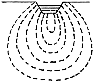
Fig. 3.
Percolation and absorption are described as follows by Beresford in Punjab Irrigation Paper, No. 10, “The Irrigation Duty of Water.” Percolation consists in flow through the interstices of boulders, shingle, gravel or coarse sand. The flow is similar to that in pipes. The water percolating into the soil from a channel, extends downwards and spreads outwards as it descends. None of it goes upwards. In fine sand and ordinary soil the interstices act like capillary tubes. The water is absorbed as by a sponge and it remains in the soil by virtue of capillarity. Owing to the combined action of capillarity and gravity the water spreads in the manner shown by the dotted lines in Fig. 3. The amount of absorption from a channel will be greater the greater the area of the wetted surface. In a high[17] embankment with narrow banks, the absorption ceases when the water reaches the outer slopes, except in so far as it is evaporated from the slopes. Moreover high embankments are generally in clayey soil. If banks of sand are constructed on a layer of clay (Fig. 4.) and well rammed, the absorption ceases as soon as the banks are saturated and the channel then holds water as well as any other except for evaporation from the outer slopes, but if the bed and subsoil are also of sand the absorption of the water will be far greater. Absorption ceases when the water extends nearly down to the level of the subsoil water, i.e., to a point where the effect of absorption from above plus gravitation is equal to the effect of absorption from below minus gravitation. If a bottle is filled with water and a small sponge jammed into the neck and the bottle turned upside down, the sponge becomes saturated but no water will be given out. But if a dry sponge is placed in contact with the wet one it will absorb moisture until saturated.
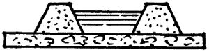
Fig. 4.
It is known that the loss of water is greatly influenced by the nature of the soil. When water is turned into a dry channel or onto a field, the loss is at first great. It decreases hourly and daily and eventually becomes nearly constant, tending to reach a fixed amount when the water extends down to nearly the level of the subsoil water. Observations made by Kennedy on loamy fields near the Bari Doab Canal in India showed that on a field previously dry the rate of absorption is given by the equation
y = ·0891 x ·86.
[18]
Where y is the depth of water absorbed in feet and x is the time in hours. The observations extended over eight days. Denoting by c the depth of water in feet absorbed in one hour, it was found that on a field on which no rain had fallen for two months, c was ·04 to ·05 but on the second watering of the crop about a month later c was ·02 to ·03 and about the same on a third watering. It was found that at the first commencement the rate of absorption was much affected by the state of the surface of the ground but that the effect was only temporary. The losses were found to be as follows:
| Day. | Loss per Day. | Loss per Hour. (c) |
||
|---|---|---|---|---|
| Feet. | Feet. | |||
| 1st | 1 | ·36 | ·057 | |
| 2nd | 1 | ·13 | ·047 | |
| 3rd | 1 | ·07 | ·046 | |
| 4th | 1 | ·02 | ·043 | |
| 5th | ·96 | ·041 | ||
| 6th | ·90 | ·037 | ||
| 7th | ·80 | ·033 | ||
| 8th | ·77 | ·032 | ||
| Total | 8 | ·01 | ||
In the eight days the total loss was almost exactly eight feet.
The losses by absorption in the various channels of certain canals has been estimated to be as follows:—
[19]
| Channel. | Nature of soil. |
Mean depth of water in Channel. |
Value of (c) |
Loss per Million square feet of wetted surface. |
Remarks. | |||||
|---|---|---|---|---|---|---|---|---|---|---|
| Feet. | c. ft. per sec. | |||||||||
| Main | Line | Upper Bari Doab Canal | Shingle and Sandy Soil | 6 | ·035 | 9·7 | - | Fairly reliable estimates based on discharge observations. | ||
| „ | „ | Sirhind Canal | Sandy Soil | 7 | 9·0 | |||||
| Branches | Upper Bari Doab Canal | Loam | ·0079 | 2·2 | ||||||
| „ | Sirhind Canal | Sandy Soil | 5·2 | |||||||
| Distributaries | Upper Bari Doab Canal | Loam | ·012 | [4] | 2·3 to 4·4 (average 3·3) |
- | Somewhat rough estimates. | |||
| „ | Sirhind Canal | Sandy Soil | 5 to 12 (average 8·0) |
|||||||
| Watercourses | Upper Bari Doab Canal | Loam | ·015 to ·045 |
[4] [5] |
3·3 to 20 (average 9·4) |
|||||
| „ | Sirhind Canal | Sandy Soil | 7 to 60 (average 22) |
|||||||
[20]
Some information as to losses of water is also given in Chapter IV. Art. 2.
The relative losses of water in the channels of the Upper Bari Doab Canal were as follows:—
| Relative Loss. |
|
|---|---|
| In main line and branches | 20 |
| In distributaries | 6 |
| In watercourses | 21 |
| Used in the fields | 53 |
| Total | 100 |
The reasons for the great variation in the value of c are not properly known. The depth of water is not likely to have much influence on it. It is well known that the fine silt carried by the water tends to render the channels watertight when it deposits. The canals and branches receive either no deposits or deposits consisting chiefly of sand. The distributaries, especially in their lower reaches, receive deposits of fine silt which is only occasionally cleared away. The watercourses receive similar deposits but they are very frequently cleared out by the cultivators. This is perhaps the reason why the rate of loss of water in the watercourses is nearly three times as great as the rate of loss in the distributaries of the same canal. On the Sirhind canal the distributaries have more branches than on the Bari Doab canal and the watercourses are smaller. This accounts for the different relative losses in the two cases. The sandy nature of the soil on the Sirhind canal accounts for the general higher value of c on that canal.
[21]
The following formula has been deduced as giving the loss by absorption on a Punjab Canal.
P = 3·5 √d WL 1,000,000
Where P is the loss by absorption in c. ft. per second in a reach whose length is L, width (at water level) W and depth d. According to the formula the loss per million square feet is 10·5 c. ft. per second when d is 4 ft. and 7 c. ft. per second when d is 2 feet, These figures do not agree with those in the preceding table and it is clear that there are not yet sufficient data from which to construct a formula.
The first steps taken on the Bari Doab Canal, and subsequently on other canals, to reduce the losses of water, consisted in the reduction in the number of watercourses. This will be referred to again (Chapter II. Art. 9). Further steps will be considered in Chapter V.
—The number of acres irrigated annually by a constant discharge of 1 c. ft. of water per second is called the “duty” of water. In India on perennial canals the duty may be as much as 250 or even 300 acres. On inundation canals which flow for only five months in the year and are situated in tracts of scanty rainfall and light or sandy soil, the duty may be only 70 acres. The duties of most existing canals whether in India or elsewhere, are known only approximately. The duty is calculated on the average discharge entering the canal at its head less the water which is passed out at escapes. It thus includes all losses of water. The duty varies not only as between one canal and another but on the same canal from year to year. It[22] depends on the character of the soil, a sandy soil requiring more water than a clayey soil. It also depends on the rainfall. A moderate amount of rain causes the canal water to go further, but heavy rain may enable some crops to do without canal water or may permit of the concealment of canal irrigation. The duty also depends on the kind of crops grown, on the losses in the channels by absorption and on the quantity of water available. A liberal supply of water leads to carelessness in the use, but a very restricted supply is largely wasted owing to the shortness of the “turns” or rotational periods of flow in the different channels.
There is an obvious connection between the duty of water and the total depth of the water, known in India as “delta,” given to the fields. Calculations are much simplified, while still being accurate enough for all practical purposes, by assuming that the number of seconds, (86,400) in a day is twice the number of square feet, (43,560) in an acre. Assuming this to be the case a discharge of 1 c. ft. per second for a day gives 2 acre-feet, i.e., it will cover an acre of ground to a depth of 2 feet in a day; and in six months it will cover 100 acres to depth of 3·65 feet. In Northern India the year is divided into two halves in each of which a crop is grown and the duty is calculated for each crop. In this case, if the flow of a canal has been continuous, a duty of 100 acres per cubic foot of its mean discharge per second, corresponds to a total depth of 3·65 feet over the area irrigated. Generally the flow in the half-year has not been continuous. In other countries, and in India on canals other than the perennial canals, the periods of flow vary a great deal. The duty cannot be calculated from delta or vice versa until the period of flow is stated.
[23]
The daily gauge-readings and daily discharges corresponding to them, having been booked, the discharges are added up. The total, divided by the number of days on which the canal has been running, gives the average daily discharge. Suppose that during the “kharif” or summer crop which is considered to last from 1st April to 30th September or 183 days, the canal was closed for 13 days and that the total of the daily discharges on the remaining 170 days comes to 850,000 c. ft. per second. The average daily discharge is 5,000 c. ft. per second. Suppose the kharif area irrigated to be 500,000 acres, the kharif duty is 100 acres. To find delta the total of the daily discharges has to be multiplied by the number of seconds in a day and divided by the number of square feet in an acre (these figures are, as already stated, very nearly in the ratio of two to one) and divided again by the number of acres irrigated. Thus, in the above case, delta is very nearly 850,000 × 2500,000 or 3·4 feet. For comparing the results of one canal or one year with another, delta is the more convenient figure to take. As soon as the areas irrigated by the canals are known for any crop, the Chief Engineer of the province issues a statement of the value of delta for each perennial canal and compares them with those for previous years. The value of delta for the Punjab canals ranges from 3 to 4 feet for the kharif and from 1·8 to 2·1 feet for the “rabi” or winter crop. Individual canals vary greatly, the worst having nearly twice as high a figure as the best. The differences are due to the causes already mentioned.
Although the figures of duty take no account of the number of days a canal was closed, they are the most convenient standard for judging generally of the work[24] likely to be done by a projected canal. It will readily be seen that figures of duty are not exact and are only an approximate guide. The delta figures are, on the perennial canals of the Punjab, also worked out for each month of the crop, the volume of water used from the beginning of the crop up to the end of the month being divided by the area irrigated up to the end of the month. But when irrigation is in full swing, some little delay occurs in booking the fields. Moreover the same field is watered a number of times during the crop and much depends on whether waterings have just been given or are just about to be given. The figures are useful to some extent for comparison. The figures for the rabi crop of 1908-09 were as follows, the figure for March being the final figure for the crop.
| Up to end of | Oct., | Nov., | Dec., | Jan., | Feb., | March. | ||
|---|---|---|---|---|---|---|---|---|
| Progressive value of delta. |
- | 1·69 | 1·34 | 1·29 | 1·47 | 1·71 | 2·05. | |
One great principle to be followed in order to obtain a high duty is to restrict the supply of water. A cultivator whose watercourse is always running full may waste great quantities of water, but if he knows that it is only to run for a few days out of a fortnight he will use the water carefully. It is not, of course, meant that the water kept back is run into escapes and wasted. It goes to irrigate other lands. The available supply of water should be spread over as large an area of land as just, and only just, to suffice.[6] Other methods of improving the duty are the reduction in the number of watercourses, the apportionment of the sizes[25] of outlets, watercourses and distributaries to the work that they have to do, careful attention to the distribution of the water and the prevention of wastage due to carelessness.
[6] A system of lavish supply is in most cases likely to lead to harm by water-logging of the soil or its exhaustion by over-cropping or to raising of the spring level and injury to the public health.
The following information concerning duties is taken from Buckley’s Irrigation Pocket Book:—
| Place. | Rabi Duty. |
Kharif Duty. |
|||||
|---|---|---|---|---|---|---|---|
| Acres | Acres | ||||||
| Upper India (Punjab and United Provinces) |
135 | to | 237 | [7] | 49 | to | 120 |
| Lower Chenab Canal[8] (Punjab) |
133 | to | 134 | 47 | to | 88 | |
| Bengal | 56 | to | 130 | 57 | to | 113 | |
| Bombay | 85 | to | 118 | 58 | to | 159 | |
The period of flow in each case would be six months or less.
The average rabi duties on the Lower Chenab and Upper Bari Doab Canals, in the Punjab, calculated on the discharges at the distributary heads, for periods of 3 and 5 years respectively, ending March, 1904, were 208 and 263 acres respectively, but in the latter case 11 per cent. of the area received only “first waterings.” For the kharif the figures are 100 and 98 respectively.
[26]
In Italy the duty is 55 to 70 acres, in Spain from 45 to 205 acres, in the Western States of America generally 60 to 150 acres. In South California the duty is 150 to 300 acres, when, as is usual, surface irrigation is employed, but 300 to 500 acres with subsoil irrigation, the water being delivered in a pipe below ground level (Chapter V.)
In basin irrigation in Egypt the duty is 20 to 25 acres, but the period of flow is only 40 days. The basins are flooded to about 3 feet in depth.
—The tract of country to be dealt with in an irrigation project may be limited either by the natural features of the country, by its levels, by the quantity of water available or by financial considerations. If the tract is small or narrow, and particularly if it is not very flat, it may be obvious that there is only one line on which the irrigation channel can conveniently be constructed but in any considerable scheme a contour plan of the whole tract is absolutely necessary. The surveys for such a plan are expensive and take time and it is desirable, as far as possible, to settle beforehand the area over which they are to extend. This may be done to some extent by the examination of any existing levels and of the tract itself. Very high, sandy or swampy ground, whether occurring at the edge of the tract or in the middle of it, may have to be left out. The remainder, as already mentioned, is called the commanded area. When land occupied by houses or roads or which is very much broken, or which for any reason cannot be irrigated, has also been deducted, the balance is the “culturable commanded area.”
[27]
Either before or after the culturable commanded area has been approximately ascertained, the proportion of it which is to be irrigated must be settled. This depends on local circumstances. In India the supply of water is calculated on the supposition that a fraction, generally from ¹⁄₃ to ³⁄₄, of the culturable commanded area will be irrigated each year. The rest will be lying fallow or be temporarily out of use or be used for crops which do not require canal irrigation. The restriction of the area is necessary either because the supply of water is limited or in the interests of the people. Too liberal a supply of water tends, as already stated, to over cultivation, and exhaustion and water-logging of the soil.
The next step is to estimate the duty and the discharge of the canal and then to fix its main dimensions. In Northern India the duty in the rabi is higher than in the kharif. It may be 200 acres in the rabi and 100 acres in the kharif. Local circumstances determine which crop has the greater area. Suppose that it is estimated that both will be equal. Then the total annual area for which water is to be provided must be divided by two and this gives the kharif area. During the kharif there is usually an ample supply of water and the kharif mean supply of the canal is based on the kharif area and the kharif duty. The full supply is not run all through the crop because the demand fluctuates, the demand being greatest when all the crops have been sown and when there is no rain, but from experience of other canals the ratio of the kharif full supply to the kharif mean supply can be estimated. The ratio is generally about 1·25. On the kharif full supply depends the size of the channel, every channel being constructed so as to carry a certain “full supply”[28] or maximum discharge and the top of the bank being made at such a height that there shall be a sufficient margin or “free-board” above the “full supply level.” The canal runs full provided that there is a sufficient supply in the river or that the water level of the river is high enough—this last condition referring to canals which have no weir in the river—and provided also that there is a sufficient “demand” for the water. At other times a canal runs with less than full supply. This generally occurs throughout most of the rabi, the supply of water in the river being then restricted. The distributaries are generally run full or ³⁄₄ths full, some being closed, in turn, to give water to the others. In the case of a country where there is only one crop in the year, the average discharge of the canal can be found by dividing the area by the estimated duty. The F.S. discharge can be assumed to bear such a relation to the average discharge as may be found by experience to be suitable. On some Indian inundation canals the F.S. discharge is taken as twice the average discharge.
The F.S. discharge of the canal having been arrived at, the alignments of the canal and branches are next sketched out on the contour plan and certain tracts and discharges are assigned to each branch. The gradients can be ascertained from the levels of the country and the cross-section of the channel can then be sketched out. If the velocity is too great for the soil “falls” can be introduced. The above procedure will enable a rough idea to be formed of the cost of the earthwork of the scheme. The cost of the headworks and masonry works and distributaries can be best estimated by obtaining actual figures for existing works of similar character, the distributaries being reckoned at so much[29] per mile. The probable revenue which the canal will bring in will depend upon the rate charged for the water and the cost and maintenance, matters which can only be determined by local considerations based on the figures for existing canals.
The masonry works on a canal consist of the headworks and of bridges, regulators and drainage crossings. The principles of design for such works have been dealt with in River and Canal Engineering. It is of course economical to make a bridge and fall in one. If the off-take of a distributary is anywhere in the neighbourhood the fall should of course be downstream of it. The positions of the falls should be fixed in accordance with these considerations. If the longitudinal section is such that the position of the fall cannot be much altered, it may be feasible to divert a road so that the bridge may be at the best site for the fall. In the case of a railway crossing, a skew bridge is often necessary. In the case of a road crossing it may be feasible to introduce curves in the road but here also a skew bridge is often necessary.
[30]
—In the design of head works no very precise rules can be laid down. Some general ideas can however be given as to the chief points to be attended to and some general and approximate rules stated. In every case a large scale plan of the river is of course required and also a close examination of it and study of its character. An attempt to forecast its action is then possible. Gauge readings for several years and calculations of discharges are of course necessary. If the bed of the river, in course of time, rises upstream of the weir or scours downstream of it, a large amount of protection to the bed and banks will become necessary. Some description of headworks and weirs, with a plan of the headworks of the Sirhind Canal, India, has been given in River and Canal Engineering, Chapters IV. and X. Remarks regarding the collection of information for such works are given in Chapter II. of the same work. It is also explained how, by keeping the gates of the under-sluices closed, a “pond” is formed between the divide wall and the canal head so that heavy sand deposits in the pond and does not enter the canal. By closing the canal and opening the under-sluices the deposit is scoured away.
The best site for the headworks of a canal depends on the stability and general character of the bed of the river but in deciding between any two proposed sites, the question of the additional cost of the canal, if the[31] upper site is adopted, has to be taken into account. Such cost may, in rugged country, be considerable.
In the case of Indian perennial canals, the head is often close to the hills where the river bed is of boulders and shingle and fairly stable, but it is often at a distance from the hills and in such cases a gradual rise in the bed of the river, even in the absence of a weir, is more probable than scour. Such a rise may necessitate a raising of the crest of the weir and of the bed of the canal.
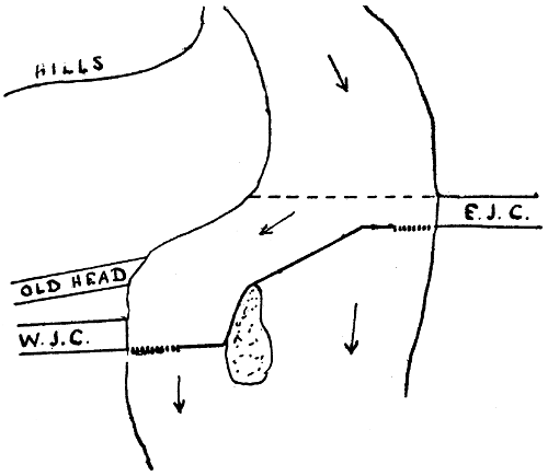
Fig. 5.
In the general arrangement of a headworks a great deal depends on local conditions. Sometimes the river runs in a fairly straight and defined channel and the weir can then be run straight across it. Sometimes, as in the case of the Ganges Canal, there is a succession of islands and various short weirs are required in the different channels. At the heads of the Eastern and Western Jumna Canals, the river, on issuing from the hills, widens out (Fig. 5.) and the weir is built obliquely[32] and not in a straight line. Its crest is higher at the east than at the west side. There are under-sluices at both sides. The upstream end and west side of the island are revetted. The old head of the Western Jumna Canal, as shown in the figure, existed long before the advent of the British, and a temporary weir, made of gabions filled with stones, was constructed across the river every year during the low water period and swept away during the floods. To have carried the weir along the line shown dotted, the head of the Western Jumna Canal being of course brought up to it, would apparently have been feasible and cheaper, but the off-take would have been in shallow water because of the curve in the river, and there would have been no current along the face of the head regulator of the canal.
The level of the floor of the under-sluices is generally about the same as that of the bed of the canal. The sill—made to exclude shingle and sand as far as possible—of the canal head regulator may be 3 feet higher and the crest of the weir 6 to 9 feet higher. The top of the weir shutters is 1 to 2·5 feet above the F.S. level of the canal which may be 5 feet or more above the bed of the canal. If the weir is provided with falling shutters the width of the waterway of the under-sluices may be about ¹⁄₁₂th of the width of the waterway of the weir alone, otherwise about ¹⁄₈th.
In nearly all cases the weir has a flat top and flat slopes both upstream and downstream. In a case where the river bed is of sand, the depth of water on the crest of the weir in floods may be 15 feet and the velocity 14 or 15 feet per second. The downstream slope of the weir may be about 1 in 15, and the upstream slope 1[33] in 6. Where the river bed is of boulders the velocity may be still higher. The faces of the weir are usually of hammer-dressed stone. A lock for the passage of rafts is added if necessary.
Unless the banks of the river are high, it is necessary to construct embankments to prevent the river water, when headed up by the weir during the floods, from spilling over the country with possible damage to the canal. If the river has side channels they have to be closed. The stream may also have to be trained, by means of guide banks or spurs, so as to remain in one channel and flow past the canal head and not form shoals against it. Where the river is unstable, it may shift its course so as to strike the weir obliquely and this may cause excessive heading up at one side of the weir. In such cases it is usual to divide the weir into bays or sections, each about 500 feet long, by “divide walls” running at right angles to the weir.
The free-board or height of the masonry walls and tops of embankments above H.F. Level is about 5 feet.
The span of each opening in the under-sluices is generally 20 to 35 feet. The piers may be 5 feet thick. It is usual to make each alternate pier project upstream further than the others so that long logs coming down the river during floods, broadside on, may be swung round and not be caught and held against the piers.
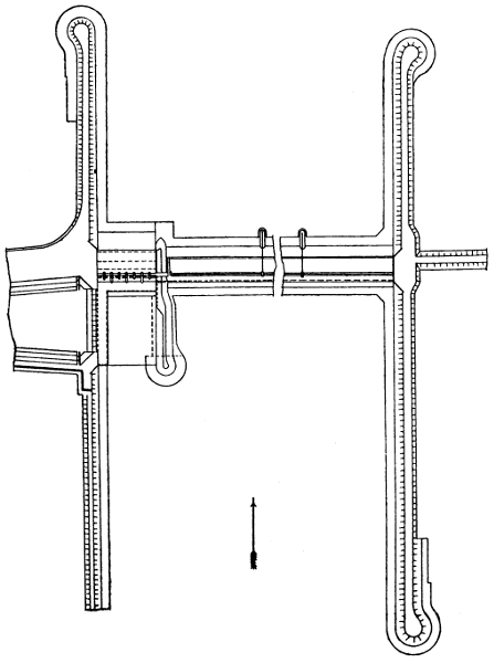
Fig. 6.
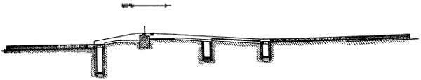
Fig. 6A.
Figs. 6 and 6A show the headworks of the Upper Chenab Canal now under construction (Chapter IV.) The site is in a low flat plain, but no better site could be found. The weir consists of 8 bays of 500 feet each. The crest is 10 feet above the river bed and the falling[34] shutters 6 feet high. The slopes are 1 in 6 and 1 in 15. The bulk of the work is rubble masonry in lime. The lower layer upstream of the crest is of puddle; upstream of the second line of wells it is rubble masonry in half sand and half lime; upstream of the lower line of wells it is of dry stone and there is an intermediate layer of rubble masonry in lime with the stones laid flat. Below[35] the crest there is a wall of masonry 9 feet thick and on the crest there are two strips of ashlar between which the shutters lie when down. The extreme upstream and downstream portions of the bed protection are of dry stone and 4 feet thick while next to the weir are concrete blocks 2 feet thick resting on dry stone. The width of the crest is 14 feet, of the weir 140 feet, of the protection 70 feet upstream and 110 feet downstream.[36] The guide banks have tops 40 feet wide and 18 and 14 feet above the crest of the weir in the upstream and downstream lengths respectively, the side slopes being 2 to 1 and the water slope being covered, up to H.W. level, by dry stone pitching 4 feet thick. The left guide bank runs upstream for 3,250 feet from the centre line of the canal and the right 2000 feet from the line of crest shutters. The under-sluices have 8 bays of 35 feet each and the canal head regulator 36 openings of 6·5 feet each, the large openings shown in the figure being sub-divided. The crest of the weir is no less than 10 feet above the river bed and the shutters add 6 feet to this. The floor of the under-sluices is 4 feet higher than the river bed. There is thus ample allowance for a possible rise in the river bed.
—The contour map, besides showing the contours of the country to be irrigated and of a strip of country, even if not to be irrigated, which will be traversed by the main line, should show all its main features, namely:—streams, drainages, railways, roads, embankments, reservoirs, towns, villages, habitations, and the boundaries of woods and cultivated lands. It should also show the highest water levels in all streams or existing canals. A map showing as many as possible of the above features should be obtained and lines of levels run for the contours. In doing this, the points where the lines of levels cut or pass near to any of the above features or boundary lines, should be noted. It may be necessary to correct inaccuracies in the plan or to supply defects in it. The greater the trouble taken to do this the less will be the trouble experienced later on.
[37]
The heights of the contour lines will, in very flat country, have eventually to be only 1 foot apart. This will necessitate running lines of levels half-a-mile apart at the most, and preferably 2000 feet apart, the pegs in each line being about 500 feet apart. In less flat country the heights of the contour lines can be further apart than 1 foot. Whatever distance apart is decided on for them, the survey should be done once for all. On one of the Indian canals in flat country, the lines of levels were at first taken 5 miles apart, the branches roughly aligned and then further surveys made. This led to great expense and delay and the procedure has not been repeated.
In making a contour survey, a base line, as centrally situated and as long as possible, should be laid down, with side lines parallel to it near the boundaries of the tract. The cross lines at half-mile or other intervals should then be laid down. Some of them may run out beyond the side lines. Circuits of levels should be run along the base line, the side lines and the two extreme cross lines and be carefully checked. The remaining cross lines should then be levelled. All the levels having been shown on the map the contours should be sketched in. The scale of the map for a large project may be two inches to a mile. If it is likely that the survey will have to be extended, it will be easier to do this by prolonging the base line and running more cross lines, than by prolonging each of the cross lines already surveyed. This can be borne in mind when selecting the base line.
—On the contour map the proposed alignments of the canal, branches, distributaries, and escapes, determined after careful[38] consideration of all matters affecting them, are shown. The tracts to be irrigated by each branch and each distributary are now marked off, the “irrigation boundaries” following approximately the valleys and lines of drainage. Any large tracts of land which cannot be irrigated are of course shown and are excluded. Forests or other lands which are not to be irrigated should be similarly dealt with, otherwise confusion is likely to arise later. The commanded area dependent on each distributary is now ascertained from the map. A certain percentage being deducted for scattered unculturable areas the culturable commanded areas are obtained. The proportion to be irrigated (in India in the kharif) having previously been decided, the number of acres to be actually irrigated by each distributary is arrived at.
The next step is to ascertain the discharges.[9] A general duty for the whole canal having been estimated by considering the actual figures for other canals the full supply of the canal at its head is arrived at. (Chapter I, Art. 6). In Northern India it will be the kharif duty and kharif full supply. Since some water is lost by absorption in the channels, the duty of the water on a branch is higher than that of the whole canal based on its head discharge, and the duty on a distributary is higher still. In designing a canal, an attempt has to be made to estimate the losses of water in the main canal and branches, so that the duties of the branches and distributaries may be estimated and[39] the channels designed accordingly. On the Western Jumna Canal the figures were estimated to be as follows:—
| Kharif. | Rabi. | |
|---|---|---|
| Average discharge at canal head (c. ft. per sec.) | 3536 | 2755 |
| Duty based on the discharge (acres) | 98 | 138 |
| Estimated loss of water in canal and branches (c. ft. per sec.) | 400 | 300 |
| Average discharge at distributary head (c. ft. per sec.) | 3136 | 2455 |
| Duty based on the discharge (acres) | 111 | 154 |
[9] In this Article and in the rest of this Chapter it is assumed that the canal is a Northern Indian one. Any modifications necessary to suit canals in other countries will readily suggest themselves.
The question of duty is one which if not carefully considered, may cause some confusion. A canal and branches, having been designed with certain assumed duties and with discharges based on certain values of N in Kutter’s co-efficient, have, let it be supposed, been constructed to a greater or less extent. When the time comes for constructing the distributaries, the engineers concerned may have different ideas, based on later experience, as regards the probable duty and the most suitable value of N. If they design the distributaries with a higher duty and a lower value of N, it is obvious that they can provide more distributaries than at first designed, or can increase their lengths. In either case they would provide for an increased commanded area. If they do not do this, they ought to adhere to the values at first proposed, thus making the channels larger than, according to their ideas, would be necessary. These larger channels will be able to do more irrigation, by an increase, not in the commanded[40] area, but in the proportion of it which is irrigated. Any other course would result in the canal carrying more water than could presumably be used by the distributaries. Again, the question how the assumed duty was arrived at may need consideration. It may have been arrived at by taking the duty figures of some existing canal, based on discharge figures which were the result, not of observed but of calculated discharges, and if the calculations were based on a value of N which experience has proved to be wrong, a correction is obviously needed. Many mistakes of the kinds indicated above have been made, not perhaps in the case of a project which has been recently got up and is then quickly carried out in its entirety, but in one which is carried out slowly or after a long period has elapsed or in one which consists of extensions of an existing system. So great, however, is the elasticity of a channel—by which is meant its capacity for adapting itself to varied discharges, a small change in the depth of water causing a great change in the discharge—and so considerable has been the uncertainty as to the real duty to be expected, that any mistakes made have not usually resulted in any serious trouble.
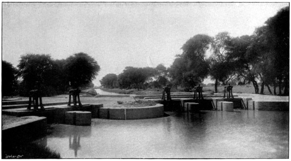
BIFURCATION AT TAIL OF CANAL.
The Distributaries have Gates and Winches.
To face p. 41.
It has been stated (Chapter I, Art. 2) that it is not desirable to let one channel tail into another. In old canals a distributary used sometimes, after running parallel to a canal, to be brought back towards it and tail into it. The advantage of this was that the distributary had not to be made very small towards the tail and that, if the demand abruptly ceased, the distributary was not likely to breach. The principle was, however, essentially bad. The lower part of the distributary was obviously too near the canal and not[41] centrally situated as regards the irrigated strip. The portion at the extreme tail was superfluous. Again, whatever volume of water was carried through the distributary and back into the canal, was needlessly detached instead of being kept in bulk. Moreover the duty of water on such a distributary cannot be ascertained without a tail gauge and the observation of discharges at the tail. There are similar objections to one distributary tailing into another. Each should be separate and distinct.
A major distributary is one whose discharge is more than 40 c. ft. per second. It may be as much as 250 c. ft. per second. A branch, as soon as it reaches a point where its discharge becomes only 250 c. ft. per second should be considered as a major distributary. A minor distributary is one whose discharge is from 8 to 40 c. ft. per second. A minor distributary is nearly always a branch of a major distributary. There are instances of “direct minors,” i.e., minors taking off from canals or branches. Such a minor, unless its discharge is a large fraction of that of the canal which supplies it—and this can seldom be the case—is objectionable because the petty native official who has to see to the regulation of supplies can manipulate the supply easily and without detection, and the number of persons irrigating from it being small, he can make private arrangements with them. On the Sidhnai Canal there are some half-dozen distributaries each of which had one or two minors which took off close to the head of the distributary. The people who irrigated from the minors managed to get the heads shifted and taken off direct from the canal, on the ground that, the water level in the canal being higher than in the distributary, there would be better[42] command and less silt deposit. The irrigation on all these minors ran up to a figure far in excess of what had been intended, to the detriment of lands further down the canal. The minor heads have all been retransferred to the distributaries, the difficulty as to command being got over, as it should have been at first, by constructing weirs in the distributaries. The fall in the water surface at the distributary head, i.e., the difference between the water level in the canal and that in the distributary downstream of its head but upstream of the weir, is quite trifling or even inappreciable.
In some of the older Indian canals it was the custom to place the heads of distributaries, not just above a fall but several hundred feet above it, the idea being that the distributary then received less silt. This practice has now been discontinued. There is no valid reason for following it.
The question whether, when a channel crosses a road on the skew, a skew bridge should be constructed or curves introduced into the road or channel, is one which requires some consideration. As far as possible the lines of channels should be fixed so as to cross important[10] roads on the square or with a small angle of skew. In the case of main canals or branches, the introduction of special curves is generally out of the question, but if the road is not straight something can be done by shifting the line one way or the other. In the case of “major” distributaries, curves can to some extent be introduced. In the case of “minor” distributaries it is often possible to curve the channel, with a radius of say[43] 500 feet, so that it will cross the road at right angles. There is very little objection to a skew bridge if the angle of skew is not great. The angle of crossing having been made as near to 90° as possible, the bridge can be made skew though not necessarily so much askew as the road. Slight curves can be introduced into the road. When the road is made askew, a bridge on the square involves at least three considerable curves (Fig. 7) and the taking up of extra land. It also causes, in perpetuity most likely, a more or less inconvenient and unsightly arrangement and one which, in most countries, would not be tolerated. When the angle of skew is not great, it is best to introduce no curve at all into the road. In the case of a “village” road, which may be more or less undefined and liable to be shifted, the difficulty about land may not be great, but even in this case the angle of crossing should, if possible, be kept near to 90°, especially in the case of minors, and where curves have to be introduced into the road they should be suitable ones. Abrupt angles are not only unsightly but are unfair to the cart drivers. The crossings of village roads by the minors of a certain great modern canal have been stigmatised as “hideous.” Indian canals can afford to do work properly.
[10] In India “district” and “provincial” roads.
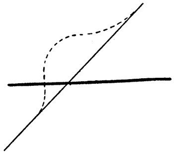
Fig. 7.
[44]
—Before a canal system can be properly designed, it is necessary to determine certain points in connection with the working of the distributaries. A distributary is intended to irrigate a certain kharif area. Its average kharif supply is determined from the assumed kharif duty. It generally runs full in the kharif but not always. In a very dry tract such as the Montgomery district of the Punjab, the demand is so great and so steady that a distributary practically runs full through the greater part of the kharif. In such a case the canal or branch must be so designed that it can keep all distributaries full at the same time. Its F.S. discharge will be the sum of all the F.S. discharges of the distributaries plus the losses of water by absorption.
But in other cases, especially if the rainfall is considerable, a distributary does not require its full supply, either all through the kharif or for long at a time. An estimate must then be made of what it will require. It may be estimated that its requirements will be met if, during the period of greatest demand, it is closed for two days out of a fortnight and receives full supply for the remaining twelve days. In this case, since the various distributaries need not all be closed on the same days, the canal or branch can be so designed that it will carry a full supply equal (after deducting losses) to ⁶⁄₇ths of the aggregate full supplies of the distributaries. In other cases the fraction may be ³⁄₄ths. It is likely to be lower the greater the rainfall of the district. Even in the case when the distributaries run full through nearly the whole of the kharif, there will be periods when they only run with about ³⁄₄ths full[45] supply. If full supply were run at such times, many of the outlets would discharge more water than was required, the cultivators would partly close them, and breaches in the banks of the distributary might result. Thus the water level of a distributary must always be so arranged that it will have a good “command” when it is running with about three-fourths of the full supply discharge. The water level with ³⁄₄ths full supply is generally ·5 to ·75 feet below the full supply level but it should be calculated in each case. Generally it will be correct to make the water level, when ³⁄₄ full supply is run, about 1 foot above the high ground traversed by the distributary, excluding any exceptionally high portions of small area. A more exact method is given in Art. 9. The greater the proportion of the culturable area which is to be irrigated, the less should be the area of any high land which is excluded. The F.S. levels of the distributaries at their off-takes must be settled in accordance with the foregoing remarks, and these F.S. levels must be entered on the plan. Neglect to thus fix the F.S. levels of distributaries before designing the canals has frequently led to trouble.
The head needed at a bifurcation in order to get the supply into a branch or distributary is always small unless the velocity is high. For a velocity of 3 feet per second the head required is only about ·16 ft., for 2 ft. per second ·1 ft.
On an Inundation Canal which has no weir across the river, the mean supply downstream of the regulator (which is built a few miles down the canal lest it should be damaged by the shifting of the river) is, as has been mentioned, about half the full supply. The command[46] in such canals is not generally very good. A distributary can often obtain only mean supply and it should be designed so as to command the country when it is carrying mean supply. A detailed description of Inundation Canals in Northern India, is given in Punjab Rivers and Works.
Let M, F, m, f, be the mean and full supply discharges at the heads of a canal and of an average distributary on it and let the number of distributaries be n. It has been seen (Chap. I. Art. 6.) that M = ·8F about. Let k be the proportion of the supply lost by absorption in canal and branches. Then n m = (1 - k) M = ·8 (1 - k) F. If the distributaries all run with full supplies—at the time of greatest demand—for 4 days out of 5, then,
n f = 1·25 (1 - k) F
fm = 1·25·8 = 1·56
Since k depends on the wetted area, it is not likely to be so great for F as for M, but the above gives a general idea of the ratio of the full kharif discharge to the mean kharif discharge. On a large canal the circumstances of the distributaries will not all be similar. Some will run full for a greater proportion of their time than others. They can be divided into groups and the ratio of the full to the mean supply calculated for each group. The mean supply is, as above stated, obtained from the area to be irrigated, and the duty as estimated at the distributary head.
At one time a system was introduced of making distributaries of large size with the idea of running them for short periods. One reason given for abandoning[47] this arrangement, was that there was a tendency to run such a distributary for too long. This reason is not very intelligible. It would be applicable to any distributary which was not intended to be run without cessation. The result would be that some other distributary would be kept short of water and this would imply extremely bad management. The chief reason against such a distributary is the greater cost of its construction. It would effect a saving of water. The ratio of the discharge to the wetted area would be high, though this would be to some extent neutralized by the greater frequency of closures, since, when water is admitted to a dry channel, the absorption is at first great. There would also be some difficulty in the distribution of the water because of the short period for which it would remain open. It will be seen (Chapter III. Art. 5), that it is desirable to open and close always at the same hour of the day. An ordinary distributary might run for 11 days out of 14. One of double the size could not conveniently be run for 5¹⁄₂ days. A distributary can always be enlarged if necessary, but if made too large it is extremely difficult to make it smaller.
It was also, at one time, usual to make minors, when there were several on a distributary, of large capacities so that they ran in turns. The preceding remarks apply to this case. The system has been abandoned.
—The apportioning of discharges to the various channels having been effected as described in Art. 2, the designing of the canal and branches is proceeded with. Rough longitudinal sections of all the lines are prepared by means[48] of the contour map, the ground levels being shown at intervals of one foot—or whatever the vertical distance between the contours may be—and the horizontal distances obtained from the map by scaling.
On these longitudinal sections the lines proposed for the bed and F.S. levels are shown reach by reach and also the mean velocities and discharges.
The laws of silting and scouring and the principles on which channels should be designed are fully gone into in River and Canal Engineering. It is there explained that, for a channel of depth D, there is a certain critical velocity, V₀, which just prevents the deposit of the silt, consisting of heavy clay and fine sand, found in Indian rivers—this silt enters the canal in such immense quantities that the canal silt clearances would be impossible if much of it was deposited in the channels—that sand of grades heavier than ·1 may deposit in the head of a canal and well nigh threaten its existence, that the clear water entering the canal in winter may pick up and carry on some of the sand but that proper steps for preventing the deposit in the canal can be taken at the headworks. This last question has been referred to in Art. 1. The following additional rules for designing canals in Northern India are chiefly taken from those given by Kennedy in the explanatory notes to his Hydraulic Diagrams, which are in use in the Irrigation Branch in Northern India.
[11] Appendix A in River and Canal Engineering deals with some instances of fallacies in questions concerning flow in open streams. An extract from it describing a remarkable divide wall recently constructed at the head of the Gagera branch, Lower Chenab Canal, is given in Appendix A of this book.
Experience shows that in designing Irrigation Channels in the plains of India in accordance with Kennedy’s figures, the maximum ratio of bed width to depth of water is as follows:—
| Discharge, c. ft. per second |
10 | 25 | 100 | 200 | 500 | 1,000 |
|---|---|---|---|---|---|---|
| Ratio | 3·5 | 4 | 4·5 | 5 | 6 | 6 |
The actual gradients of the canals generally range from about 1 in 8,000 for a main canal to 1 in 2,000 for the tail of a distributary, but near the head of a canal where the bed is of boulders and shingle, the gradient may be as steep as 1 in 1,000.[12] The velocity in this last case may be 5 feet per second but generally it is not more than 3 or 4 feet per second in canals and branches, and 1 to 2 feet per second in distributaries.
[12] On the Upper Jhelum Canal, 1 in 970.
[51]
In designing the channels, N, in Kutter’s co-efficient, may be taken as ·0225 or ·020, according to judgment. For new and smooth channels ·020 is generally correct. A channel generally becomes rougher by use but sometimes it becomes smoother. Cases have occurred in which N has been found to be ·016. This question is discussed in Hydraulics, Chap. VI.
The bed width of a canal is reduced, where a distributary takes off, in such a way that when the canal and distributary are both running full, the depth of water in the canal continues to be uniform and the flow to be uniform. When the distributary is closed there is heading up in the canal upstream of the off-take, but not enough to make any appreciable difference unless the capacity of the distributary is a large fraction of that of the canal and even then no harm is likely to result.
The preceding rules and principles being taken into consideration, the channels are designed. The bed levels, gradients and depths are so arranged as to give the velocities suited to the soil and to maintain the proper relation of depth to velocity. The bed width is arranged so as to give the proper discharge. The full supply level of the canal and branches has also to be so arranged that it shall be higher, at each distributary off-take, than the full supply level of the distributary. It is desirable to be able to give a distributary its full supply even when the canal is low. Generally the slope of the country along any line is greater than would be suitable for the bed, and “falls” are introduced. The off-take of a distributary is generally just above a fall and there is generally an ample margin between its[52] F.S. level and that of the canal. The discharge of the canal during the greater part of the rabi may be only about half the full supply. This discharge should be estimated and the water level corresponding to it calculated and shown on the longitudinal section. If possible the levels should be so arranged that even with its least supply the water level in the canal will enable full supply to be given to a distributary. If this cannot otherwise be managed it may be necessary to construct a regulator in the canal below the head of the distributary so that, during low supplies, the water can be headed up. It has been stated in River and Canal Engineering, Chapter IV., that such heading up, if temporary, is not at all likely to cause silt deposit in the canal. The designing of the distributaries is not proceeded with at this stage.
Since no irrigation is usually done directly from the canal and branches, they are designed without any particular connection between the level of the water and that of the country traversed. Dangerously high embankments are of course avoided as far as possible. The bed is designed at such a level that the excavation and embankment at any place will be, as nearly as possible, equal. Land in India is cheap. When the excavation exceeds the embankment the balance is made into a spoil bank. When the excavation is less than the embankment the balance is got from borrow-pits.
The side slopes of channels in excavation are generally 1 to 1, in embankment 1¹⁄₂ to 1. The sides of channels of small or moderate size usually become about ¹⁄₂ to 1, or even vertical, by the deposit of silt on the slopes.[53] This reduction of area is allowed for in the design i.e. the bed width is so designed that the channel will carry the required discharge, not with the side slopes as executed, but when they have become ¹⁄₂ to 1. In large canals however the sides do not always silt up but rather tend to fall in. When this is expected to occur the allowance above described is not made. Berms are left so that if any part of the sides fall in, the bank will not also fall in. The berms also allow of the channel being widened if that ever becomes necessary. Type sections are given in Figs. 8 and 9.
—Figs. 8 and 9 show the banks and spoil.
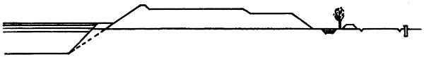
Fig. 8.
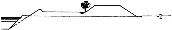
Fig. 9.
The scale is 6 feet to an inch. The depth of water, in this particular case, is 7 feet, and the bank, excluding the small raised bank, 2 feet above the water. The inside edge of the bank, where the small raised bank is shown, is kept parallel to the canal for a considerable distance. Its position is got by drawing a line, shown dotted, at, generally, 1¹⁄₂ to 1. The embanked part of the slope is actually made at 1¹⁄₂ to 1, but the excavation is at 1 to 1, so that a berm is left. The[54] width of this berm of course varies as the depth of digging varies. If there is likely to be much falling in of the sides the berm can be made wider, the dotted line starting, not from the edge of the bed, but from a point further in. On an inundation canal in sandy soil the berm may be 20 feet wide. In figure 8, the inside slope above the berm is supposed to have silted up to a slope of 1 to 1. In cases where it is expected the whole inside slope will silt to ¹⁄₂ to 1 the dotted line, to give the edge of the bank, can be shifted towards the channel so that the berm at the ground level when the channel is excavated will be very small for the minimum depth of digging. There is no need for the inner edge of the bank to run parallel to the canal for great distances. Its position can be shifted whenever suitable and the width of the berm at ground level varied. This prevents the occupation of a needlessly great width of land. It used at one time to be not unusual to make a bank with a berm on the land side, similar to that formed by the spoil in Fig. 8, but at about the level of full supply in the canal. The principle is not a good one. Salient angles are liable to be worn away. If earth has to be added to a bank to strengthen it, the whole can be widened or the rear slope flattened. The roadway is shown 18 feet wide, which is nearly the maximum. For the drainage of rain water it has a transverse slope, away from the canal, of about 1 in 50. The small raised bank on the canal side is to give safety to wheeled vehicles. It is provided on the patrol[55] bank[13] on main lines and places where there is much traffic or where there is plenty of width of bank to spare. When the ground level is, for a considerable distance, above the proper bank level—which is at a fixed height above the F.S. Level—so that the road and its side-drain have to be cut out, much earthwork can be saved by allowing them to be at a higher level and, in the case at least of the non-patrol road, giving the road a reduced width.
[13] A canal has an unmetalled driving road—called the “patrol road” or “inspection road” on one bank. This road is reserved for the use of officials. Otherwise, it would soon be cut up and worn away, and the cost of repairs would be excessive. The patrol road should be on that bank which is, in the morning (the time when inspections are usually made) in the shade of trees planted on the landward side. Trees are not usually planted near the water edge as they are sometimes blown down. In Northern India the canals generally flow in a southerly direction, so that the left bank is best for the patrol bank. On the other bank there is a bridle road which is open to the public. Near a rest house—unless there is a bridge actually at the place—the patrol road should be on the same bank as the rest house. It can if necessary cross at the first bridge. Frequently there is also on one or both sides of the canal a “boundary road,” which is open to the public, along the toe of the outer slope. Along a distributary there may be a boundary road on one side. It is generally the only road which can take wheeled traffic, and in this case it should be reserved for officials unless money is provided to keep it always in repair. Officials have to be on tour for weeks or months at a time, and in all weathers. Their baggage carts also have to precede and follow them. Anything which facilitates their touring about and seeing things for themselves is, in India, most desirable. At a watercourse crossing the boundary road along a distributary should be taken by a curved incline up on to the bank and down again. Thus not only is the cost of a culvert saved, but any touring official who is driving obtains a view of the channel which he cannot get from the boundary road.
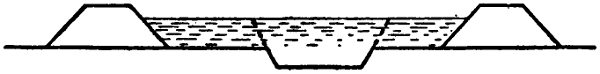
Fig. 10.
In shallow digging, the plan of setting back the banks (Fig. 10) and letting silt deposit as shown by the dotted lines, is one which should be followed much oftener than it is. It not only gives eventually a very strong bank, but it enables the borrow pits, from which the earth for the banks is got, to be dug inside the banks. Outside borrow pits, besides being a source of expense, owing to compensation having to be paid to those in whose land[56] they are dug, cause great areas of hollows which are not only unsightly, but are often full of stagnant water and are thus a fruitful source of mosquitoes and malaria. Insufficient attention has hitherto been paid to this matter.
In designing each reach of a canal or branch, type cross sections should be drawn out for several different depths of digging, e.g., one for very shallow digging, i.e., where the bed is little, if at all, above the ground level, one for deep digging where the ground is higher than the water level, and one for the “balancing depth,” where the area of the channel excavation is equal to the earth required for the banks. In calculating the earthwork the sectional area of the digging or of the embankment is taken, whichever is the greater.
The proper width and height of bank for any channel depends partly on the maximum depth of water in the channel, and partly on the discharge. Given a depth of water of say 8 feet, a breach will obviously be more disastrous with a great volume of water than with a small volume. The following statement gives some figures suitable to the rather light and friable soils of Northern India, but the question is largely one of judgment. Generally a low and rather wide bank is preferable to a higher and narrower one. If a road, with or without the small raised bank next the canal, is required, special widths can, of course, be arranged for. A 14-foot bank is required for a driving road.
[57]
| Top Width of Bank. |
Height of Bank above F. S. |
Greatest Admissible Discharge. |
Greatest Admissible Depth of Water. |
||
|---|---|---|---|---|---|
| Feet. | Feet. | C. ft. per sec. |
Feet. | ||
| 20 | 2 | 12,000 | 12 | ||
| 18 | 2 | 8,000 | 12 | ||
| 16 | 2 | 5,000 | 11 | ||
| 14 | 2 | 3,000 | 10 | ||
| 16 | 1 | ·5 | 2,000 | 9 | |
| 14 | 1 | ·5 | 1,500 | 9 | |
| 12 | 1 | ·5 | 1,200 | 8 | |
| 10 | 1 | ·5 | 1,000 | 7 | |
| 9 | 1 | ·5 | 700 | 6 | |
| 8 | 1 | ·5 | 500 | 5 | ·5 |
| 7 | 1 | ·5 | 400 | 5 | |
| 6 | 1 | 300 | 4 | ·5 | |
| 5 | 1 | 200 | 4 | ||
| 4 | 1 | 100 | 3 | ·5 | |
| 3 | 1 | 50 | 3 | ||
The spoil in Fig. 8 is shown at a different level from the bank proper, as it should be to give a neat straight edge to the bank. The width of the spoil may vary every chain. In Fig. 9 the spoil is raised to avoid taking up too much land. The spoil presents the best appearance when its height is kept uniform for as long a length as possible, the width varying according to necessity, When the height has to be altered, the change should be made by means of a short ramp. When the spoil is higher than the road, gaps in it are left at intervals so that rain water can pass away. When the spoil is heavy for a very short length it can, in order to avoid a short and unsightly heap, which would result from the adoption of the section shown in Fig. 9, be placed as in Fig. 8, some of it being led askew.
[58]
The small channel shown outside the bank in Fig. 8 is a watercourse for enabling trees to be grown. It has, of course, to be graded, and it may be in cutting or in embankment. If any silt clearances of the canal are likely to be necessary, the watercourse must be set back to allow room for the spoil. Such spoil, if sandy, is to a large extent washed down or blown away and does not accumulate to anything like the extent that would be expected.[14] Moreover the spoil can extend onto the watercourse when the trees have grown big, and no longer need watering. Outside the watercourse is shown the boundary road and the land boundary pillar. The small channel in Fig. 9 is a drain for rain water. It can be used as a plantation watercourse if the water is lifted.
[14] This fact has been quoted (The Pioneer Mail, “Silt,” 8th March, 1913) as showing that the silt supposed to be cleared is not really cleared. This may be the case to some extent, but shortage of spoil is little proof of it.
Where there is no spoil, some extra land, perhaps 20 feet on either bank, is usually taken up for getting earth from for repairs.
—The proposed lines of channel, determined as explained in Art. 5 should next be laid down on the ground. A line should consist of a number of straight portions. The curves should not be put in. Trial pits should be dug at intervals. Some defects in the line may at once become apparent because the contour map, owing chiefly to the lines of levels having been taken a considerable distance apart, is not perfect. A line may pass through a patch of very high or very low ground or too near to some building or other object with which it is desirable not to interfere. Alteration[59] may be desirable at a drainage crossing or at the off-take of a branch. The lines should be corrected where necessary. Sometimes the corrections may be very considerable. Allowance can be made for the alterations which will occur when the curves are laid out. Where there is doubt as to which line is the best, trial pits may be dug to obtain further information regarding the soil.
The line should now be levelled, careful checks being made, a longitudinal section of it prepared and the proposed bed, bank and F.S. level shown. The ground levels ascertained by levelling the line, are certain to disagree, to some extent, with the contour lines. The latter were got only by inference from the levels of points in the survey lines, and they should be corrected in accordance with the fresh levels now available. If the line does not seem to be the best that can be got, a fresh line can be marked on the plan and the above procedure repeated.
—As soon as the best line seems to have been found, a large scale plan of the country along its course should be made by taking bearings or off-sets from points in it to the various objects and noting where the line cuts them. On this plan will be shown the exact alignment, the curves being put in and the straight portions slightly shifted where necessary so that the line may pass at a proper distance from any buildings or other objects. But before this procedure is carried out, or while it is being carried out, the estimate for the work can be prepared from the longitudinal section already taken. Such a section is of course amply sufficient for a “project estimate,” in which only approximate figures are given, and it is quite[60] near enough for any estimate. In the case of small works which have often to be executed with great promptitude, lamentable delays have occurred owing to the engineer deferring the preparation of his estimate till he had got the line exactly fixed. Moreover there is a chance of the labour being thrown away in case the sanctioning authority directs any change in the alignment to be made.
In the case of a large scheme, a project estimate is prepared. In this the earthwork and the area of land to be occupied are calculated pretty accurately. Designs and estimates are also prepared for the headworks and for the chief regulators. For works of which there are to be many of one type—bridges, falls, distributary heads and small drainage syphons—the cost is arrived at from lump sum figures, one drawing of each kind being submitted as a type. The distributaries are approximately estimated at mileage rates. In the case of a small scheme everything is estimated in detail except perhaps the distributaries or some of them.

CANAL WITH BRIDGE AND DISTRIBUTARY HEAD.
The Head has Gates and Winches.
To face p. 61.
—A distributary is a canal in miniature and, like a canal, it may have branches. It has masonry bridges, falls and drainage syphons. It has, as already mentioned, a masonry regulator at its head. At the off-take of any branch or distributary there is a regulator in the head of the branch. If the branch takes off a large proportion of the water there is a double regulator. A distributary gives off watercourses as a canal gives off distributaries. The watercourses belong to the people and not to Government and they are cleared and maintained by the people. Each watercourse has a masonry head[61] known as an “outlet” (Fig. 11). The outlet is the point where the water passes from the hands of Government officials to those of the cultivators. The outlet is of masonry and its opening is not adjustable but is fixed in such a way that its discharge, when the distributary is full, bears, as nearly as can be arranged, the same ratio to the F.S. discharge of the distributary as the area intended to be irrigated by the watercourse bears to that intended to be irrigated by the distributary.
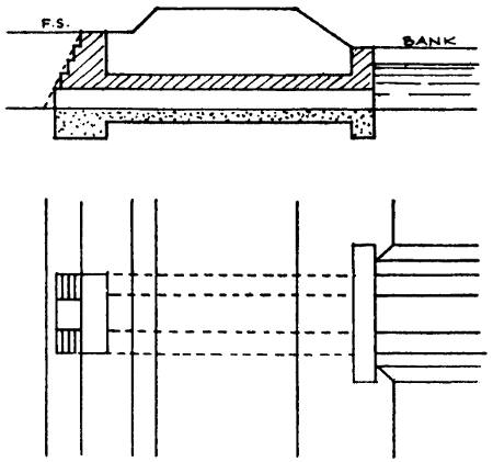
Fig. 11.
The floor of the outlet is level with the bed of the distributary. It thus draws off rolling sand which might otherwise accumulate in the distributary. Small outlets are made of earthenware pipes, about ·4 feet in diameter, laid in concrete. Two pipes, or three, may be laid side by side. If more than three would be required, a masonry opening is adopted. The discharge through an outlet, is generally 2 to 5 c. feet per second per square foot of outlet area, and the head ·1 to ·5 feet.
For the tract of country allotted to any distributary, a contour map is prepared on a fairly large scale, say 4[62] inches to a mile. On the map the line is laid down and a rough longitudinal section, showing the ground level, is prepared as in the case of a canal.
It has already been stated (Art. 4) that a distributary is so designed that its water level, when three-fourths of the full supply is run, shall be well above the level of most of the ground along its course. In other words it should have a good command. A good rule is to allow a fall of ·5 feet from the level of the water in the distributary to that in the watercourse, a slope of 1 in 4,000 for the water flowing along the watercourse, and a fall of ·3 feet for the water at the tail of the watercourse to the level of the ground. This last level is, like the other ground levels, taken from the contour map. This procedure, in short, consists in making the water level of the watercourse at its head govern that of the distributary, just as the water level in the distributary at its head was made to govern that in the canal.
The enlarged contour map of the distributary area shows, among other things, the boundaries of the lands belonging to each village. Generally a watercourse supplies water to only one village. When, however, a village is far from the distributary, its watercourse has to pass for a long distance through other villages and it would be wasteful of water to have two separate watercourses. In such cases one watercourse may serve two villages or more. When a village is near to the distributary and its land extends for a long distance parallel to the distributary, it may have several watercourses for itself alone. A watercourse can generally be most conveniently dug along the boundary line of two villages, or there may be some other line which the people particularly desire.[15] Subject to, or modified by, these considerations a watercourse is designed to run on high ground like a distributary.
[15] They also frequently wish the “chak”—the area irrigated by a watercourse—so arranged that two men who are “enemies” shall not be included in the same “chak.” This condition can be complied with only up to a certain point. Arrangements may be modified but not in such a way as to upset the proper rules.

Contour Map (part) and Line of Distributary.
The scale is 1 inch to 2 miles. The contour lines at 1 foot intervals are shown dotted, the roads by double lines. The line of the distributary, in order to follow the ridge of the country, would have gone more to the left of the plan near the village. The shifting of the line to the right brings it nearer to the centre of the irrigated tract—supposed to be the whole area shown—and enables a single bridge to be built at the bifurcation of the two roads. Suitable lines for main watercourses are shown in thin firm lines. It is assumed that the command is sufficient to enable the watercourses to run off at the considerable angles shown.
To face page 63
[63]
The great object is to reduce the total length of channels, i.e., minors and watercourses. No watercourse can be allowed to run alongside of or near to another. It may run alongside a canal or distributary when really necessary to gain command but not otherwise. The longer the watercourse the larger the chak. The discharge of an outlet may be anything up to 4 or 5 c. feet per second. This limits the size of a chak. If a chak is too big it can be split up or a minor can be designed. Very small chaks are to be avoided, but it is difficult to fix a minimum size. The irrigation boundary of the distributary, as fixed in the project, is shown on the map but in practice it will not be exactly followed. For various reasons the boundaries of a chak may run somewhat outside it or stop short of it.
Where a distributary gives off a minor and there is a double regulator, watercourses should, as far as possible, be taken off from one or other of the branch channels and not from upstream of the double regulator. Otherwise, irregularities are likely to occur, both of the regulators being partially closed at the same time—a thing which is never necessary in legitimate distribution of the supply—in order to head up the water and increase the discharges of the outlets.
[64]
A watercourse nearly always gives off branches and generally a system of turns is arranged by the farmers among themselves, each branch in turn taking the whole discharge of the watercourse for a day or part of a day, the other branches being closed by small dams of earth. To irrigate a field alongside the watercourse a gap is cut in its bank. For fields further away, smaller channels run off from the watercourses at numerous points. Several gaps and several field channels may be in flow at one time, and there is a dam in the watercourse below the lowest one.
Occasionally, on an old canal, one watercourse crosses another, the lands irrigated being at different levels, but such crossings do not often occur in systems of watercourses laid out according to modern methods. They are, however, quite legitimate.
The lines of the main watercourses are sketched on the map, their irrigation boundaries shown on it, and F.S. discharges allotted to them according to the areas which are to be dependent on them. In order that this may conveniently be done the “full supply duty” or “full supply factor” for the distributary is obtained. It bears the same ratio to the ordinary duty that the mean supply bears to the full supply. The total of the F.S. discharges of all the watercourses should, with an allowance for loss by absorption in the distributary, be the same as the F.S. discharge of the distributary. If the results are very discrepant it shows that the sizes of the outlets need revision. Possibly they may all be too large.
In “colonization” schemes where a canal is constructed to irrigate waste lands—which are the property[65] of Government and which are divided into square blocks and given out to colonists—Government has complete control of the watercourse system, and can arrange it exactly as desired, but in other cases landowners often strenuously oppose the passage of watercourses through their lands. Compulsory procedure according to legal methods is tedious, but the practical rule is not to let anyone have water until any watercourses which are to pass through his land have been not only agreed to but constructed.
In ordinary cases Government possesses no power as to the precise line on which a watercourse is dug. It fixes the site of the outlet and assigns certain land to it, and sketches out the line of the watercourse. If the people choose to alter the line they can do so, but great alterations in the main watercourses are not generally feasible.
The positions of the outlets[16] having been settled after discussion with the cultivators, a table is prepared showing the chainage of the outlets, the probable head or difference between the F.S. level of the distributary and of the watercourse, and the F.S. discharge. From this the sizes of the outlets are calculated and shown in another column. If the length of the outlet barrel is not more than 5 or 6 times the diameter—in the case of a barrel whose cross section is not round or square, the mean diameter—the discharge can be calculated as for a “short tube,” but if longer the formula for flow in pipes should be used, allowance being, of course, made for the head lost at the entrance. The outlets generally consist at first of wooden “shoots” or long tubes, rectangular in cross section. This is because, after they have been tested[66] by a year or two years’ working, the sizes nearly always require adjustment and the cultivators often wish to have the site shifted.
[16] The positions can be slightly altered by the Engineers for any sufficient reason.
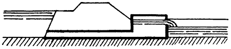
Fig. 11.
The uncertainty as to the proper size of an outlet is due to several causes. If the command is very good there may be a clear fall from the outlet into the watercourse. In this case the discharge depends only on the depth of water in the distributary, and is known pretty accurately. But ordinarily the outlet is submerged, and its discharge depends on the difference between the water levels in the distributary and in the watercourse. The latter level is not fixed. The cultivators can lower it, to an extent which depends chiefly on the distance of the fields from the distributary, by deepening or widening the watercourse. In this way the discharge of the watercourse is increased except when a dam is temporarily made in it for the purpose of irrigating any comparatively high land. This uncertainty as to the discharge can in some cases be got over by building a cistern (Fig. 11). This has the same effect as raising the level of the barrel, the real outlet being no longer submerged, and the discharge depending on the depth of the crest of the overfall below the water in the distributary. But such cisterns add greatly to the cost of an outlet, and they can only be adopted when there is good command. A great cause of uncertainty as to the proper size of an outlet is the variability of the duty of the water on the watercourse. The soil may be clayey or sandy, the watercourse may be short or long, the crops grown may be ordinary ones or may be chiefly[67] rice, which requires three or four times as much water as most other crops, and the cultivators may be careful or the opposite. Again, the people may, if the outlet gives a plentiful supply, often keep it closed, but there is no record of such closures nor would the people admit that they occur. These causes may all operate in one direction—on a whole distributary this cannot happen to the same extent—and thus enormous differences in duty may occur. There is no way of arriving at the proper size for an outlet except trial. Observations of the discharges of the outlets are of very limited use. The discharge may vary according to the particular fields being irrigated. Observations of discharges will be useful in cases where the people complain, or when the discharge is obviously much greater or much less than intended and will in such cases enable temporary adjustments to be made, but by placing a dam in a watercourse and turning the water on to a high field near its head the people can make it appear that the discharge is only a fraction of what it should be.
On any distributary there are generally some watercourses which have a poor command, the head at the outlet being, say, ·1 ft. or even less. Probably the irrigation is a good deal less than it should be. In such cases the rules may be set aside and a liberal size of outlet given. The size may be 2 or 3 times the calculated size. There is no harm in this. The irrigation cannot increase much. Similar cases frequently occur on inundation canals especially near the heads of canals or distributaries.
The construction of masonry outlets on a distributary is not usually a final settlement of the matter. Further adjustments become necessary. This matter will be dealt with in Chapter III.
[68]
On the older canals little or insufficient attention was given to the question of the sizes of outlets. The sizes were far too great and, as long as all the outlets in a distributary remained open, water could not reach the tail. The distributary used to be divided into two or three reaches and the outlets in the upstream reaches used to be closed periodically. The closures had to be effected through the agency of native subordinates and the system gave rise to corruption on a colossal scale. The tail villages never obtained anything like their proper share of water. The upper villages were over-watered and the soil was often water-logged and damaged. Moreover, even if all concerned had the best intentions, it was impossible to stop all leakage in the closed outlets, except by making earthen dams in the watercourses, and great waste of water resulted from this.
The water level of the distributary with ³⁄₄ full supply, designed so as to be at least ·5 ft. above the water level in the watercourse heads—or to be 1 foot above high ground if this simpler plan is adopted—is drawn on the rough longitudinal section and also the line of F.S., falls being introduced where desirable and the gradients, F.S. depths of water and widths of channels being arranged, just as in the case of a canal, so as to give the required discharges, velocities suited to the soil and a suitable ratio of depth to velocity. The bed width of a distributary decreases in whole numbers of feet. The decrease occurs at outlets but not at every outlet. As the channel becomes smaller its velocity becomes less and this necessitates, according to the laws of silting and scour, a reduced depth of water. The height and width of the banks in the tail portion of a distributary[69] should be made rather greater than elsewhere—regard being had to the depth and volume of the water—so that breaches may not occur when the demand abruptly slackens. The longitudinal section of a distributary should have horizontal lines for showing the following:
| 1. | Datum | 5. | Draw-off | 9. | Bank width | 13. | Depth of digging |
| 2. | Bed gradient | 6. | F.S. discharge | 10. | Height of bank | 14. | Bed level |
| 3. | Village | 7. | Velocity | 11. | F.S. depth | 15. | Ground level[17] |
| 4. | Land width | 8. | V₀ | 12. | Bed width | 16. | Chainage[18] |
A specimen of a longitudinal section is shown in Fig. 12. It shows only a few of the above items. In practice all would be shown, large sheets of paper being used with all the lines and titles printed on them.
When a distributary is constructed the side slopes are made 1 to 1 in excavation and 1¹⁄₂ to 1 in embankment. The sides usually silt up till they are ¹⁄₂ to 1 or even vertical. The silting up to ¹⁄₂ to 1 is, as in the case of a canal, allowed for in the designing. The berms are left so that, if any part of the side falls in, the bank will not also fall in. They also allow of widening of the channel. The remarks made in Art. 6 regarding the design of banks, apply to distributaries, especially large ones.
On a distributary there is seldom much spoil. Where there is no spoil, a strip of land, outside the bank and 10 feet wide, can be taken up on either bank from which to obtain earth for repairs. On a minor the width of the strip is sometimes only 5 feet.
[70]
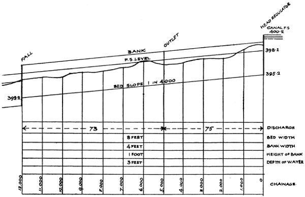
Fig. 12.
Larger illustration (82 kB)
When a distributary passes through land which is irrigated from wells, it frequently cuts through the small watercourses which run from the well to the[71] fields. In such cases, either a syphon or a supplementary well is provided at Government cost. If several watercourses, all from the same well, are cut through, it is generally possible to combine them for the purpose of the crossing. The wishes of the cultivators in this matter are met as far as possible.
The procedure as regards laying out the line on the ground, digging trial pits, correcting the line and preparing the estimate are the same as for the case of a canal.
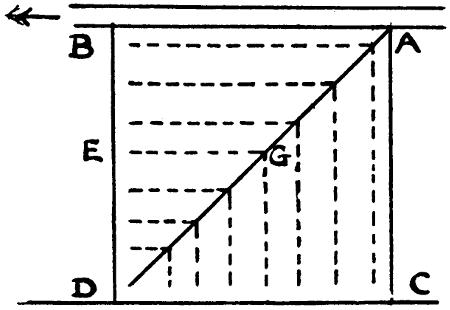
Fig. 13.
—Let AB (Fig. 13) represent a portion of a distributary, the irrigation boundary CD being two miles from AB. In order to irrigate a rectangular plot ACDB, the main and branch watercourses would be arranged somewhat as shown by the full and dotted lines respectively. Generally, the whole supply of the main watercourse would be sent in turn down each branch, the other branches being then dry. The average length open is AGE. The ends of the branches lie on a line drawn say 200 feet from the lines BD and DC, since it is not necessary for the watercourses to extend to the outside edges of the fields. Within the field there are small field watercourses which[72] extend to every part of it. By describing three rectangles on AC, making AB greater than, equal to and less than AC, it can be seen that the average length of watercourse open is least—relatively to the area of the block—when AB is equal to AC, i.e., when the block served by the watercourse is square as in the figure. If AB is 4 times AC, the average length of watercourse open is increased—relatively to the area of the block—in about the ratio of 3 to 2. Moderate deviations from a square are of little consequence.
Suppose two parallel distributaries to be 4 miles apart, each of them being an average Indian one, say sixteen miles long with a gradient of one in 4,000, and side slopes of ¹⁄₂ to 1, the bed width and depth of water at the head being respectively 13·5 feet and 2·9 feet, and at the tail 3 feet and 1 foot. The discharge of the distributary, with N = ·0225, will be 72 c. ft. per second. The discharge available for the 2 mile strip along one bank will be 36 c. ft. per second. If the duty is 300 acres per c. ft. the area irrigated in this strip will be 10,800 acres, or 1,350 acres for each of the eight squares like ACDB. Each main watercourse would then have to discharge 4·5 c. ft. per second. Supposing its gradient to be 1 in 4,000 and its side slopes ¹⁄₂ to 1 and N to be ·0225, its bed width would be 3 feet and depth of water 1·45 feet. Its wet border would be 6·3 feet, and its average length 5280√2 + 5280 - 200 or 12,546 feet. Its wetted area would be 79,040 square feet, and the total wetted area of the 16 watercourses—on the two sides of the distributary—would be 1,264,640 square feet. The wetted border of the distributary itself is 19·5 feet at the head and 5 feet at the tail, average 12·25 feet, and its wetted area is 5,280 × 16 × 12·25 or 1,034,880 square feet.
[73]
If the distributaries were two miles apart, there would be twice the number of distributaries, and each square would be one square mile instead of four. Each watercourse would have to discharge 1·125 c. ft. per second. It would have a bed width of 2 ft., depth of water ·8 ft., wet border 3·8 feet, length 6,173 feet, and wetted area 23,457 feet. The total wetted area of the 64 water courses would be 1,501,248 square feet, or 18 per cent. more than before. Each distributary would discharge 36 c. ft. per second, the bed width and depth at the head being 10 feet and 2·24 feet, and at the tail 2 feet and ·75 feet. The wet border at the head and tail would be 14·5 and 3·5 feet, mean 9 feet, and the wetted area of the two distributaries would be 1,520,640 square feet or 50 per cent. more than before. Supposing that, in the case of the larger distributary considered above, the 2-mile square was considered too large, and that rectangles 1 mile wide were adopted, so that the watercourses were a mile apart, their number would be doubled and their length and size reduced. Their total wetted area would not be greatly affected, but the difference in the wetted areas of the two small distributaries as compared with the one large one, would be the same as before. In practice, of course, distributaries are not always parallel, nor are the blocks of irrigation all squares, and frequently, owing to peculiarities in the levels of the ground or the features of the country, or the boundaries of villages, it is necessary to align the watercourses in a particular manner, or to construct more than one watercourse where one would otherwise have sufficed, but the above calculations show in a general way the advantages of large watercourses and of not placing the distributaries too near together.
[74]
It is commonly said that a watercourse discharging more than 4 or 5 c. ft. per second is objectionable because the cultivators, if there are too many of them on one watercourse, cannot organize themselves in order to work it and keep it in order. This matter is much exaggerated. On the inundation canals of the Punjab a watercourse often discharges 10 c. ft. per second, and is several miles long and requires heavy clearances, but the people have no particular difficulty in managing it. Kennedy, a great authority on questions of irrigation, states that the length of a watercourse may be three miles. This, if the angle made by a watercourse with the distributary is 45°, gives rather more than two miles as the width of the strip to be irrigated.
Suppose that a distributary instead of being two miles from each side of the irrigated strip, ran along one side of it, and was four miles from the other side. If the block were square, as before, the side of a square would be 4 miles, and each watercourse would have to discharge 18 c. ft. per second, which is far too much. The blocks would have to be rectangles, each being only one mile wide measured parallel to the distributary. It has been already seen that the length of watercourse in this case is greater than when the block is square and each side is two miles. Thus centrality in the alignment of the distributary is an advantage.
A minor distributary has been defined (Chapter II., Art. 3) as being one discharging not more than 40 c. ft. per second, but the term has come to be used to designate a branch of a major distributary, and in that sense it will be used in this article. When the shape of the area commanded by a distributary is such that watercourses[75] exceeding 2 miles in length would otherwise be required, one or more minors are often added. Frequently it is a question whether to let some of the watercourses be more than two miles long, or to construct a minor and thus shorten the watercourses to perhaps only one mile. Which method is best has not been definitely settled. It is known that the loss of water in watercourses is heavy, but if a minor is added the loss in it has to be considered. The loss must be high in any channel in which the ratio of wet border to sectional area is small. The minor also costs money in construction and in maintenance. On the whole the matter, as far as concerns cost and loss of water, is, perhaps, almost evenly balanced, but as regards distribution of the supply a system without minors is preferable. The off-take of a minor is generally far from the canal, i.e., in a more or less out-of-the-way place, and it is impossible to see that the regulation is properly carried out. Irregularities and corruption are sure to arise. Even if the supply is fairly distributed as between the minor and the distributary it is almost certain that the regulator, if a double one, will be manipulated for the illegal benefit of outlets in the distributary upstream of the bifurcation. There are sure to be some such outlets not very far distant. In any case each minor adds one, if not two, to the already very large number of gauges which have to be entered daily in the sub-divisional officer’s register (Chapter III., Art. 3), and adds also to the mileage of channel to be inspected and maintained. These considerations should, in many cases, though of course not in all, turn the scale against the construction of a minor. At one time it became usual to construct minors even when watercourses more than[76] two miles long would not otherwise have resulted. This custom was condemned some years ago, and is not likely to be re-established. Most of the difficulties just mentioned can, in the case of a minor which is not too large, either absolutely or relatively to the main distributary downstream of the off-take, be got over by making the minor head like a watercourse outlet, building it up to the proper size, removing the regulating apparatus and abolishing the reading of the gauge, but in this case the minor is not likely to be bigger than a large watercourse. Such minors should not be constructed, and any existing ones should, after the head has been treated as above, be made over to the people and considered as watercourses.
—The top of the head and tail walls of an outlet are level with the F.S. levels in the distributary and watercourse respectively. The steps in the head wall enable the cultivators to go down either to stop up the outlet or to remove any obstruction. The stepping is arranged so as to fall inside the side slope ultimately proposed. It is usual, in some places, to have the entrance to the “barrel” of the outlet made of cast iron. The cast iron pieces are made of various standard sizes. This to some extent prevents the “barrel” being built to a wrong size. A discrepancy between the size of the masonry barrel and that of the iron would be noticed, but if the masonry barrel is built too large the iron head does not always restrict the discharge. The action is the same as in a “diverging tube” well known in hydraulics.
For sizes up to about 50 or 60 square inches the barrel should be nearly square. For larger sizes the[77] height should exceed the width. Up to about 100 or 120 square inches the width can be kept down to 7 or 8 inches so that an ordinary brick can be laid across to form the roof. For larger outlets the height can be from 1·5 to 3 times the width, and the roof can be made of large bricks, concrete blocks or slabs of stone or of a flat arch of brickwork or by corbelling, but in this last case there should be two complete courses above the top of the outlet. The less the width the cheaper the roof, the easier the adjustment of size and the less the tendency to silt deposit during low supplies. If pipes are used they should be laid in concrete. If cast iron head pieces are to be used there should be several sizes of one width and the widths of the masonry outlets should be made to suit these widths.
A masonry outlet is not generally built till the watercourse has been sometime in use. The exact position of the outlet should then be so fixed that the watercourse shall run out straight or with a curve and should not be crooked.
The width between parapets should be, for a driving road or one to be made into such, 10 ft. (if the bank is wider, it should be narrowed just at the outlet site) and for a non-driving road, 8 feet to 3 feet according to the ultimate width of the bank. Earth backing should be most carefully put in and rammed, otherwise a breach may occur and the outlet be destroyed.
Various attempts have been made to provide gates or shutters for outlets. The chief result has been trouble and increased cost. If grooves are made and shutters provided, the shutters are soon broken or lost[78] by the people. Hinged flap shutters are objectionable because they are often closed by boys or by malicious persons or by neighbours who wish to increase the supply in their own outlet. The cultivator, when he wishes to reduce the supply or to close the outlet, can easily do this by obstructing the orifice with a piece of wood or an earthenware vessel or a bundle of brushwood or grass.
As regards temporary outlets, wooden outlets if large (unless made of seasoned wood and therefore costly) are liable to give great trouble. Water escapes round the outside or through the joints. Pipes may do well if laid in puddle but are brittle and costly if of large size. The irrigators may interfere both with wooden outlets and pipes and they are liable to be displaced or broken. A temporary outlet, if small, can be made of bricks laid in mud. The joints can be pointed with lime mortar. When the outlet is made permanent the same bricks are used again. But all kinds of temporary outlets are liable to give trouble especially in light or sandy soil. There is much to be said in favour of building masonry outlets at the first, making a barrel only, i.e., omitting the head and tail walls and taking the chance of having to alter the size. The alteration is not very expensive. The head and tail walls are built when the size has been finally settled. The adjustment can be made by raising or lowering the roof. This should be done over the whole length of the outlet but lowering can be done temporarily over a length of 3 feet at the tail end of the outlet. This can be done even when the distributary is in flow. A reduction over a short length at the upstream end of a barrel does not, as already remarked, necessarily reduce the discharge much.
[79]
On inundation canals the rules regarding outlets have to be modified. Great numbers of watercourses take off directly from the canals. In such cases, especially near the head of a canal, the ground to be watered is often 5 to 8 feet above the canal bed and it is wholly unsuitable to place the outlet at bed level. The cost of the tail wall would be excessive. The floor level in such cases must be at about the lowest probable cleared bed level of the watercourse, say, in order to be safe, a foot or half a foot below the usual cleared bed of the watercourse, so that water need never be prevented from entering the watercourse. The irrigators should be consulted as to the floor level and their wishes be attended to as far as possible. For lift outlets the floor should be at the bed level of the canal or distributary. If this bed is to be raised in the course of remodelling, the floor should be at the old bed level until the bed has actually been raised, unless there is a weir which raises the water. It is necessary that lift outlets should work however small the canal supply may be. In a distributary or small canal, the head wall should be built up to F.S. level but in a canal with deep water the head wall should reach up to just above the roof of the outlet and be submerged in high supplies. The stepping of the head wall should be set back if the channel is to be widened and should project into the channel if the channel is to be narrowed. The centre line of the channel near the outlet site must always be laid down and the outlet built at right angles to it and also at the correct distance from it.
Occasionally there is a wide berm, say 20 ft. or even 50 ft., between a channel and its bank. In such a case the outlet should be built to suit the bank. The long[80] open cut is however objectionable because the people clear it and heap the spoil in Government land. Sometimes the bank, especially if it is crooked, can be shifted so as to come close to the channel at the outlet site. Sometimes the outlets on inundation canals are large. For outlets of more than 2·5 square feet in area, grooves should be provided so that the cultivators can use a gate if necessary.
—The positions and descriptions of all the masonry works of a proposed canal or distributary are of course shown on the longitudinal section of the channel and from this the discharges and water levels are obtained. The principles of design to be followed[19] for bridges, weirs, falls, regulators and syphons, are discussed in River and Canal Engineering. It is mentioned that there is no special reason for making the waterway of a regulator exactly the same as that of the stream, and that the waterway may be such as to give the maximum velocity considered desirable, and that the foundations of a bridge should be made so deep that it will be possible to add a floor, at a lower level than the bed of the stream—with the upstream and downstream pitching sloping up to the bed—so as to increase the waterway and so save pulling down the bridge in case the discharge of the channel is increased. It remains to consider certain points affecting Irrigation Canals.
[19] So far as concerns their capacity for dealing with flowing water.
The span of a bridge, where there are no piers, is generally made as shown by the dotted lines in Figure 14, so that the mean width of waterway is the same as[81] that of the channel. The arches, in Northern India, used at one time to be 60° as shown by the upper curved line, but in recent years arches of 90° as shown by the lower curved line, have frequently been adopted, the springing of the arch being below the F.S. level, so that the stream is somewhat contracted. The 90° arch gives a reduced thickness and height of abutment. It causes increased disturbance of the water, and this may necessitate more downstream protection. An advantage of having the springing not lower than the F.S. level is that this admits of a raising of the F.S. level in case the channel is remodelled, and this arrangement is still common on distributaries.
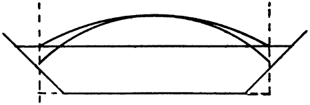
Fig. 14.
When a fall and bridge are combined, the bridge is placed below the fall as this gives a lower level for the roadway. The side walls of the fall are produced downstream to form those of the bridge.
The roads in India are generally unfenced and the banks of canals close to bridges, on both sides of the canal and both above and below the bridge, are generally more or less worn down by cattle, which, when being driven home in the evening and out to graze in the morning, go down to the stream to drink. In order to prevent this damage the banks are sometimes pitched, above the bridge as well as below it, but the cattle generally make a fresh “ghát” further away. The best[82] plan is to allow a “ghát” on one bank either above or below the bridge and to protect the other three places.
In the Punjab the widths of roadways between the kerbs and parapets of bridges respectively have been fixed as follows:—
| Kind of Road. | Near Towns.[20] | In the Country.[21] | ||||||
|---|---|---|---|---|---|---|---|---|
| Kerbs. | Parapets. | Kerbs. | Parapets. | |||||
| Provincial | 22 | 23 | ·5 | 16 | 17 | ·5 | ||
| District | 18 | 19 | ·5 | 14 | 15 | ·5 | ||
| Village | 14 | 15 | ·5 | 8 | ·5 | 10 | ||
[20] The figures show the maximum. The general width should be the same as for neighbouring bridges on the same road.
[21] The parapets should be whitewashed so as to be visible at night.
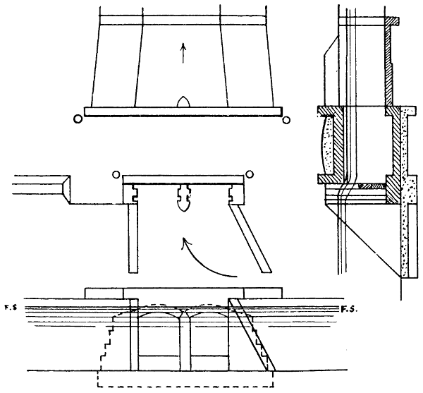
Fig. 15.
Fig. 15 shows a head regulator for a distributary. The scale is 10 feet to an inch. It has a double set of grooves for the insertion of the planks with which the regulation is effected. Only one set of grooves is ordinarily used, but when the distributary has to be closed for silt clearance and all leakage stopped, both sets of grooves can be used and earth rammed in between the two sets of planks. The floor is shown a foot lower than the bed of the distributary. This reduces the action of the water on the floor, and enables the bed of the distributary to be lowered if ever the occasion for this should arise. This is a good rule—in spite of the fact that in re-modellings the tendency is for the beds to be raised—for all regulators or bridges, a raised sill being[83] added (in regulators) to reduce the length of the needles or the number of the planks. Such sill should, where needles are to be used, be fairly wide, especially if regulation is to be done while the masonry is somewhat new. The distributary shown has a bed width of 10 ft. The span of the two openings in the head might have been four feet each, but are actually five feet, and this enables the distributary to be increased in size at any time. The pitched portion of the channel tapers. Unless needles are used, instead of horizontal planks, spans are not usually greater than 5 or 6 feet. Longer spans would give rise to difficulties in manipulating the planks. Sometimes distributary heads are built skew, but there is seldom or never any good reason for this. A curve can always be introduced below the head to give[84] the alignment the desired direction.[22] The small circles shown on the plan are “bumping posts.” On the left is shown a portion of the small raised bank at the edge of the road.
[22] The curve can be quite sharp (see Chap. I., Art. 2), and can be made, if necessary, within the length of the pitching.
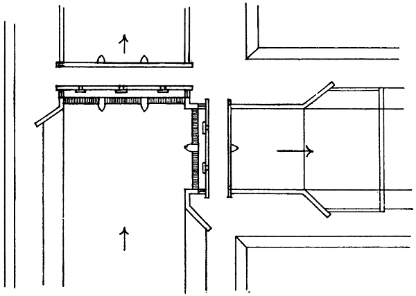
Fig. 16.
Figure 16 is a double regulator with needles. The scale is 30 feet to an inch. The spans are 15 feet. The roadway is on arches, but the regulating platform on steel beams. The needles are seen at the upstream sides of the regulators. They are worked from the platforms to which access is obtained through the gaps in the upstream parapets. The regulating platform should generally be only just clear of the F.S. level, and therefore lower than the roadway.
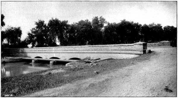
NEEDLE REGULATOR AND BRIDGE.
Needles lying on Bank.
To face p. 85.
Frequently the roadway of a bridge or small regulator is carried, not on arches, but on steel beams. The railings may be of wood or of gas pipe with the ends[85] plugged, running through angle iron posts. In the case of such a regulator the roadway is sometimes so light that camels are not allowed to cross over. This causes unnecessary hardship. Bridges are not too numerous. If the regulation is done by gates, both road and platform are carried on arches.
The regulators on inundation canals, and some on perennial canals, are not strong enough to admit of the flow of water being entirely stopped, so that the depth of water would be perhaps 10 feet upstream and nil downstream. This might cause the overturning of the piers, or the formation of streams under the floor. In such cases a maximum permissible heading up is decided on. Such orders are, in India, liable to be lost sight of in course of time, and they are, at least on inundation canals, where sudden emergencies often occur, hardly reasonable. An engine driver is not told that he must never entirely close his throttle valve. Regulators should be so designed that the water can be completely shut off.
The following remarks show the chief points in favour of needles and horizontal planks respectively.
Advantages of Needles. Needles can be placed or removed by one man.
Needles do not require hooks, etc., which are liable to be broken or lost.
A needle regulator requires few piers, and is therefore cheap.
Water falling over planks throws a strain on the floor.
[86]
Regulation with needles is easy and rapid. A jammed plank, especially if low down and not horizontal, may give great trouble.
Advantages of Planks. Floating rubbish is not liable to collect above the Regulator because the water flows over the planks.
By means of double grooves and earth filling, leakage can be quite stopped.
For large works the advantages are generally with needles, but for small works, e.g. distributary heads and shallow water, with planks. Needles 14 feet long are not too long for trained men. Planks are more likely than needles to arrest rolling sand, and this can be taken into consideration in designing double regulators. See number 8 of Kennedy’s rules, Article 5. When planks are used there should be two sets of grooves. Planks are very suitable for escape heads which have only occasionally to be opened, earth being filled in between the two sets of planks.
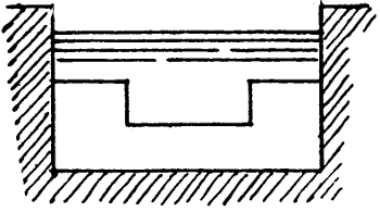
Fig. 16A
Regarding notched falls, in the case of small distributaries the notches are so narrow that they are extremely liable to be obstructed either accidentally by floating rubbish or wilfully by persons whose outlets are upstream of them. Weirs are not open to this objection, and are frequently adopted. There is not the least chance of their causing any silting worth mentioning. A simple weir if made of the proper height for the F.S. discharge, will cause a slight heading up with ³⁄₄ths of the F.S. discharge, and this unfairly benefits any outlets for a considerable distance upstream of the weir. This difficulty can be got over by making the weir as in Fig. 16A.
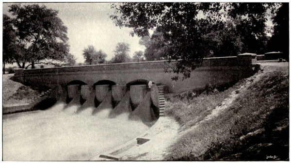
BRIDGE AND NOTCH FALL.
In this case the usual practice of placing the bridge downstream of the fall has not been followed.
The gauge well is seen on the left bank.
To face p. 87.
[87]
For cisterns below falls the usual rule for the depth is
K = H + ∛H √D
where H is the depth of water in the upstream reach, and D is the difference between the upstream and downstream water levels. Another rule for distributaries is
K = H + D3
the length of the cistern being 3 H and its width the bed width of the channel.
At “incomplete” falls, i.e., where the tail water level is above the crest, it is not unusual to construct a low-level arch, which forms a syphon. The object is to allay the surging of the surface water.
The question of skew bridges has been dealt with in Art. 3. Another question is that of the heights of bridges. Irrigation channels, especially the smaller ones, are very frequently at a high level, and bridges have ramps which are expensive to make and to maintain, and are inconvenient. The lowering of distributary bridges in such cases, so that they become syphons, or nearly so, has often been advocated and is frequently desirable. The bed should slope down to the floor and up again. The heading up can be reduced by giving ample waterway, but it will not be necessary to do this if there is head to spare. The fall in the water surface can be recognised and shown on the longitudinal section. The structure becomes one of the incomplete[88] falls above described. The crown of the arch can, if desirable, be kept above F.S. level, so that floating rubbish will not accumulate.
The width between the parapets of a regulator can be 10 feet in the case of a driving road. It may be less, according to the width of the bank, in other cases.
The upper layer of the floor of a bridge or regulator is of brick on edge. Below this there is a layer of brick laid flat, and below this, concrete of a thickness ranging from ·5 feet to 3 feet. The thicknesses of piers range from 1·5 to 3 feet.
The bricks used for canal work in Northern India are 10 inches long, 4⁷⁄₈ inches wide, and 2³⁄₄ inches thick. The thicknesses of walls are about ·83, 1·25, 1·7, 2·1, 2·5 feet, and so on.
The slopes of ramps should be about 3 in 100 for district roads, and 5 in 100 for village roads.
Railings should be provided along the tops of high walls and top of pitching near to public roads or canal patrol roads. Bumping posts should be provided for all parapets, and should not be so placed as to seriously obstruct the roadway.
The quarters for the regulating staff should, when convenient, be in the fork between the two principal branches. They may be on the bank—with foundations on pillars carried down to ground level—but not in such a position as to obstruct the road or any road likely to be made. Rests consisting of two parallel timbers bolted to blocks of masonry reaching up a foot from the ground, should be provided for the needles or planks. The bolt head should be countersunk so as not to damage the needles and planks when they are hurriedly laid down.
[89]
When two or more works are close together they should be made to conform, and the whole site should be considered with reference to a neat and suitable arrangement of works, ramps and roadways. If an outlet is near to a minor or distributary head the parapets of the two should be in line. If two masonry works of any kind are near together it is often suitable to pitch the intervening space. If there are outlets or distributaries on opposite banks they should be exactly opposite each other. Where a road crosses a bridge or regulator, the bank should be at the same level as the road, the bank being gradually ramped back to its original level. The space in front of any quarters should have a slight slope for drainage, but otherwise be at one level and be connected with the road or bank by proper ramps. The berm or bank should be made at the exact level of the top of any pitching or side wall which adjoins it. Wing walls are frequently made too short, so that the earth at their ends forms a steep slope and is worn away, and the bank or roadway is cut into. The walls should extend to such a point that the earth at their ends cannot assume a slope steeper than the slope of the bank.
It is obvious that for every masonry work there should be a large scale site plan[23] showing all roads, ramps, and adjoining works, both existing and proposed roads being shown for some little distance from the work.
[23] It is, or was until recently, in some parts of India, the custom to omit the preparation of site plans, and to leave the fixing of the exact site of a work and the arrangement of ramps and other details to the judgment of the assistant engineer who was building it. Much unsightly work resulted. A chief engineer in the Punjab recently issued some orders on the subject.
For each kind of masonry work there is usually a type design. A few of its dimensions, which are fixed, are[90] marked on it. The other dimensions are variable. It would be a great advantage to add to the design a tabular statement to show how these dimensions should vary under different circumstances.
The object of pitching upstream of bridges or regulators or downstream of bridges where there may be little or no scouring action, may be partly to protect the bank from damage by cattle or wear, or to prevent sandy sides from falling in. In such cases there may be pitching of the sides only, and it may be of brick on edge laid dry and under this one brick flat resting on rammed ballast (Fig. 17). Downstream of regulators or weirs and downstream of bridges if contracted or having piers which cause a rush of water, especially if the soil is soft, the side pitching may be as above, but with the bricks over one-sixth of the area placed on end and projecting for half their length. This “roughened pitching” tends somewhat to reduce the eddying. The bed protection should be solid concrete or blocks of concrete or masonry. Immediately downstream of regulators or weirs where there is great disturbance, both side and bed pitching may consist of solid concrete or of concrete or masonry blocks (Fig. 18).
[91]
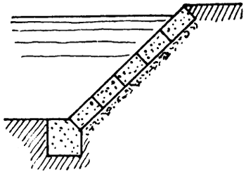
Fig. 19.
Three kinds of toe walls are shown in Figures 17, 19 and 20. The kind shown in Fig. 19 contains, for a given depth below the bed, far more masonry than the one shown in Fig. 17. It is also liable to be displaced and broken if scour occurs.
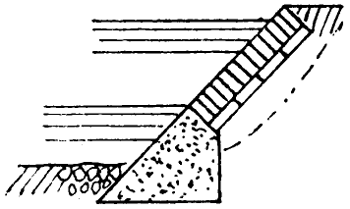
Fig. 20.
The earth should in all cases be carefully cut to the proper slope, so that no made earth has to be added. If the slope has already fallen in too much, well rammed earth should be added. The flat brick and rammed ballast can be varied as the work proceeds, more being used in soft places and less in hard.
In some parts of the Punjab, large bricks, the length, breadth, and thickness being about twice the corresponding dimensions of an ordinary brick, are made, and are extremely useful and cheap for pitching. Where the soil is sandy such bricks can be burned without cracking.
Sometimes the curtain wall which runs across the bed at the downstream end of the pitching is carried into the banks and built up so as to form a profile wall (Fig. 21).[92] This is not very suitable, because the pitching of the sides is apt to settle and leave the profile wall standing out. It is better to lay a row of blocks on the slope. If a hole tends to form in the bed downstream of the curtain wall, blocks of masonry or concrete can be laid and left to take up their own positions (Fig. 22).
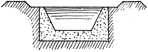
Fig. 21.
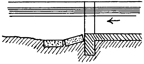
Fig. 22.
When scour of the bed or sides occurs downstream of pitching, it is sometimes said that any extension of the pitching downstream is followed by extension of the scour. This may happen if the cross section of the stream downstream of the pitched section has become greater than the pitched section. In this case there is eddying, due to abrupt enlargement of the stream where the pitching ends. The increased width and lowered bed level (not counting mere local hollows) of the stream should be adhered to in the pitching. Where the masonry of the regulator ends and the pitching begins, there will be an abrupt or tapered enlargement, but the eddies—at very low supplies there may be a fall—cannot do harm.
This principle of enlarging the pitched cross section can be followed, even in a new channel, if the soil is light and scour is feared, and for this reason the matter[93] is mentioned in the present Chapter instead of in Chapter III. It was once the custom to splay out the sides of a channel, downstream of a regulator or weir, so as to form a sort of pool in which the eddies exhausted themselves, but this gives curved banks and requires extra land and is not a very convenient or neat arrangement. Where scour of the sides is likely to occur, or has occurred, immediately downstream of the pitching the latter may be turned in as shown in Fig. 23.
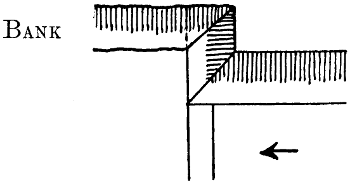
Fig. 23.
Pitching has constantly to be replaced or extended owing, generally, to failure to pitch a sufficient length or to ram well the earth under the pitching, or to use properly rammed ballast or flat brick, or to give proper bed protection, or to the use of dry brick pitching when a stronger kind is needed.
The side slopes of pitching should be 1 to 1. They can be ¹⁄₂ to 1 in rare cases, e.g., when there is no room for 1 to 1, or in continuation of existing ¹⁄₂ to 1 pitching. No absolute rule can be laid down as to the length to be pitched, but in a Punjab distributary it is often about 5 times the bed width.
On Indian canals the chainage[24] is marked at every thousand feet. Five[94] thousand feet is called a “canal mile.” The distance marks are often cast iron slabs, fixed in a cylindrical block of brickwork about 2·1 feet in diameter and 1·5 feet high, the upper edge being rounded to a radius of ·4 feet. The wedge-shaped bricks for these blocks are specially moulded. The iron slab should project about eight inches and have about a foot embedded in the brickwork.
[24] In India, instead of the simple word “chainage” the term “reduced distance” is used. It is the distance reduced to a common starting point as levels are reduced to mean sea level. The expression is puzzling to non-professionals and new comers.
On a canal having a wide bank the distance mark is put at the outer edge of the patrol bank, earth being added, if necessary, to increase the width. On a distributary with a narrow bank the mark should be on the opposite bank not the patrol bank. To enable the miles to be easily distinguished the masonry block can be sunk only ·5 foot in the ground, the others being sunk a foot. In all cases the masonry block rests on a pillar, 1·7 feet square, of bricks laid in mud, carried down to the ground level.
Profile walls (Fig. 21, page 92) used occasionally to be built at frequent intervals along a distributary. They will not prevent scour occurring, if the stream is tending to scour, unless very close together. Such walls are of some use as showing whether the channel is altering, but they are expensive and have to be altered if, as often happens, the channel is remodelled. It is a much better plan to lay down blocks—about 1¹⁄₄ foot cubes—of masonry or concrete, along the centre line at every 500 feet, with their upper faces level with the bed. If the bed scours they may be displaced but otherwise they are useful not only for showing what silt, if any, has deposited, but for showing the centre line of the channel. Without them the centre line is liable to be altered in silt clearances or berm cuttings.[95] To enable a block to be readily found and to be replaced in proper position if displaced, there should be two small concrete pillars exactly opposite to it and equidistant from it, one on either bank of the channel. Such blocks and pillars may with advantage be placed at quite short intervals on curves.
The rest houses for the use of officials on tour are generally at intervals of about 8 to 14 miles. There is generally a rest house near to a large regulator and frequently there is one near to a small regulator. This facilitates inspection work and discharge observations and it saves money, because the house can be looked after by one of the regulating staff. Not infrequently the house is placed just too far away from the regulator. Similarly if a rest house is near a railway station it should be within a quarter of a mile of it—always provided that this does not bring it too near to villages or huts—and not a mile or more away as is sometimes the case. It is also a mistake to place a rest house off the line of channel unless perhaps when it is on a district road which crosses the channel.
[96]
A large canal is under a Superintending Engineer and it often constitutes his sole charge. It consists generally of three to five “divisions,” each under an Executive Engineer. A division has two to four subdivisions, each under a Subdivisional Officer. A subdivision is divided, for purpose of engineering work and maintenance, into several, generally three or four, sections, each consisting of some 20 miles of canal and some 40 miles of distributary, and being in charge of a native overseer or suboverseer, and for purposes of water distribution and revenue, into a few sections each having, perhaps, some 30,000 acres of irrigation and being in charge of a native zilladar. As far as possible the boundaries of divisions and subdivisions are co-terminous with those of the branches of the canal. A distributary is always wholly within a subdivision. At every regulator there is a gauge reader, who, supplied when necessary with permanent assistants, sees to the regulation of the supply. If there is a telegraph office at the regulator the telegraph “signaller” may have charge of the regulation. The zilladar has a staff of some ten or twelve patwaris, who record in books the fields watered and who are in touch with the people and know when the demand for water is great, moderate or small, and for what kind of crops it is needed. In each division there is generally a Deputy Collector who is a native official, ranking as a Subdivisional Officer. His duty is to specially supervise[97] the revenue staff in the whole division. Both he and the Subdivisional Officer have magisterial powers which are exercised in trying petty cases connected with the canal.
Along a main canal and its branches there is nearly always a “canal dak” or system of conveyance of bags containing correspondence for the officials stationed on the canal or touring along it. Along the main line, and most of the way down the branches, there is a line of telegraph for the special use of the canal officials. The telegraph offices are at the chief regulators, with tapping stations, for the use of officials on tour, at the rest houses near to which the line runs.
However carefully a canal has been designed, alterations in the channels from silting and scour soon take place and they go on more or less without cessation. In a distributary, especially if the gradient has of necessity been made somewhat flat, there is quite likely to be a deposit in the upper reach. The deposit is generally greatest at the head and decreases, in going downstream, at a fairly uniform rate. It may extend for half-a-mile or less or more. Or a deposit may occur on the sides, which grow out and contract the channel. This often occurs over a great length of a distributary or even over the whole of it. Sometimes a distributary scours its bed, or the sides may fall in somewhat. Clearances of the silt and cutting of the berms are effected at intervals. Falling in of the sides may be stopped by means of bushing, and scour of the bed may be stopped by raising the crest of a fall or by introducing a weir, but in the meantime the changes cause the discharge tables for the distributary to become more or[98] less erroneous. In many cases silt deposits in the upper part of the distributary during the summer months when the river water is heavily silted and scours away again in the winter, the régime of the channel being, on the whole, permanent. The changes which occur in the branches and main canal are similar to the above and the remedies adopted are similar. On some of the older canals the scour was so serious that many intermediate weirs had to be constructed. The remarkable silting in the head reach of the Sirhind Canal has been described in River and Canal Engineering, Chapter V. The remedy consisted in keeping the gates of the under-sluices properly closed so that a pond was formed in which the river silt deposited. When necessary the canal is closed, the sluices opened, and the silt scoured away. For a plan of the headworks see fig. 24.
In working a canal, it is necessary to arrange so that the water sent down any channel is as nearly as possible in accordance with the demand. The zilladar supplies the Subdivisional Officer, every week or ten days, with an “indent” showing how much water is required in each distributary and the Subdivisional Officer makes indents on the subdivision next above. The officer in charge of the headworks thus knows what the demand is. When it is more than the supply available, the water is dealt out to the various divisions according to rules approved of by the Superintending Engineer of the canal.
Every gauge-reader has to be given definite instructions
as to the gauge reading to be maintained, until
further orders, in each distributary. At the places[99]
[100]
where the large branches take off, the gauge reader is
instructed what gauge to maintain in each. In the
event of too much water arriving, he turns the surplus
into the escape if there is one. If there is no escape he
has usually to raise the gauge readings of the branches
by equal amounts. By means of the telegraph, adjustment
is promptly effected at the headworks.
It has already been mentioned that rain may cause an abrupt reduction in, or even cessation of the demand for water. At the same time it increases the actual supply. Rain, or the signs of rain, in any part of a canal system ought always to be reported to the other parts. Owing to changes in the channels, to fluctuation in the water level of the river, especially during the night, to rain or to changes in the temperature and moisture of the air and to lack of continuous attention on the part of the gauge reader, particularly at night, there is a constant, though perhaps small, fluctuation in the water level in all parts of a canal.
It may happen that—owing to enlargement of the channels by scour, or to other causes—the channels of a canal system are able to carry more water than was intended. In such cases the channels are usually run with as much as they can carry. This may give a lavish supply and a lowered duty, but it increases the irrigated area. To restrict the supply would cause loss of revenue. Sometimes however, it is restricted to prevent water-logging of the soil. The proper procedure is to extend the canal to other tracts.
In India the farmers pay for the water, not according to the volume used, but according to the area irrigated. Different rates per acre are charged for different kinds[101] of crops according to the varying amounts of water which they are known to require. Sugarcane, which is sown in the spring and stands for nearly a year before being cut, thus extending over the whole of the kharif and most of the rabi, is assessed at the highest rate. Next comes rice which crop, though only four or five months elapse between its sowing and reaping, requires a great quantity of water. Gardens which receive water all the year round also pay a high rate. Other kharif crops are cotton and millet. The chief rabi crops are wheat, barley and “gram.”
Every field irrigated is booked by a patwari who is provided with a “field map” and “field book” for each village (perhaps 6 or 8) in his beat. The map enables him to recognise at a glance the field in which he is standing. It has a number in the map and, by referring to this number in the field book, he finds the area of the field. The patwari is also provided with a “field register” in which he books each field which is watered, showing its area and the kind of crop grown, the date of booking and the name of the owner and tenant. He goes about entering up all new irrigation and his proceedings are subjected to rigorous check by the zilladar and Deputy Collector, and also by the engineering staff. At the end of the crop the entries are abstracted into a “demand statement” in which all the fields cultivated by one person are brought together and, the proper rates being applied to them, the sum payable by this person is arrived at. The demand statement goes to the Collector of the district, who levies the money and pays it into the Treasury to the credit of the canal concerned. There is a special charge for any land watered in an “unauthorised manner.” This includes[102] taking water when it was another man’s turn, or taking it from an outlet which has been wilfully enlarged or—in some districts—from another man’s outlet even with his consent. The sizes of the outlets are carefully apportioned to the land allotted to them and the area which they irrigate is constantly being looked into in order to see if the size is correct or needs altering. If a man borrows water from another outlet such borrowing may or may not come to light but in any case confusion as to outlet sizes results.
The water rates charged for ordinary authorised irrigation are decidedly low. In one district there was a case in which a man, being unable to get as much water as he needed from his own outlet, took water for some fields, by permission, from a neighbour’s outlet. This being found out he was charged for those fields at double the usual rate. He continued regularly to use the water and to pay the double rate. There were several cases of this kind in that one district.
Since payment for the water is not made according to the volume used, the cultivators are more or less careless and wasteful in using it. As a rule they over-water the land and frequently damage or spoil it by water-logging. They do not always keep in proper order the banks of the watercourses. The banks often breach and water escapes. Any area thus flooded is charged for if it is seen by an official. The engineers have power to close such a watercourse until it is put in order, but this would cause loss of revenue and is not often done. The real remedy for all this is, as already stated, rigid restriction of the supply. The people will then learn—they are already learning—to use water more economically.
[103]
When the crop in any field or part of a field fails to come to maturity, the water rate on it is remitted. The failed area is known, in the Punjab, as “kharába.” On some canals the failed areas are liable to be large and an irrigation register, in order to be complete, has to show them or, what is the same thing, to show both the gross and the net areas, the latter being the area left after deducting the kharába or remitted area.
—In every canal, branch and major or minor distributary there is a “head gauge” below the head regulator. At every double regulator there is a gauge in each branch and also an upstream gauge. These gauges are used for the regulation of the supply. The zeros of the gauges are at the bed levels. Tables are prepared showing the discharges corresponding to each gauge reading—except in the case of upstream gauges—at intervals of ·1 foot.
The question often arises whether it is necessary to have a gauge near the tail of a distributary. If the outlets have not been properly adjusted and if water does not reach the tail in proper quantity, a tail gauge is absolutely essential and its readings should be carefully watched by the Sub-divisional Officer. To take no action until complaints arise or until the irrigation returns at the end of the crop show that some one has suffered, is not correct. When it is known that sufficient water always reaches the tail, a tail gauge is not necessary.
There may be intermediate gauges on a canal or branch or distributary. For convenience of reading they are usually at places where a distributary or minor takes off or where there is a rest house. They serve to[104] show whether the water level at that place alters while that at other places is stationary, and thus give indications of any changes occurring in the channel. The number of such intermediate gauges should be rigorously kept down. In fact hardly any are necessary. The gauge register which the Subdivisional Officer has to inspect daily, is, in any case, voluminous enough.
At a double regulator it is never necessary, except as a very temporary arrangement in case of an accident, to partially close both channels at once. One or the other should be fully open. The upstream gauge reading shows whether this rule is being adhered to. If the bed levels of all three channels at the regulator are the same, the reading on one or other of the downstream gauges should be about the same—for the fall in the water passing through an open regulator is generally negligible—as that of the upstream gauge. In other cases the difference in the bed levels has to be taken into account.
Immediately downstream of the off-take of a channel, there is, unless the water flows in without any appreciable fall, much oscillation of the water. For this reason the gauge is frequently fixed some 500 feet down the channel. This is anything but a good arrangement. The gauge-reader’s quarters are close to the off-take and he will not keep going down to the gauge. Moreover an official coming along the main channel cannot see the gauge. The gauge should be close to the head and in a gauge well where oscillations of the water are reduced to very small amounts. The upstream gauge requires no well.[25]
[25] For further details as to gauges see Appendix G.
[105]
All gauges should be observed daily, in the morning, and the reports sent by canal dak, post or wire at the earliest possible moment. This should be rigidly enforced. The register should be posted and laid before the Subdivisional Officer daily with the least possible delay. It is only in this way that the Subdivisional Officer can keep proper control of the water, and detect irregularities. Sometimes trouble arises owing to the gauge reports not coming in regularly. The suboverseer can be made responsible for seeing to this matter as regards all the gauge readers in his section. Gauge readers often reduce the supply in a branch or distributary at night for fear of a rise occurring in the night and causing a breach. This is to save themselves the trouble of watching at night. They are also bribed to tamper with the supply and run more or less in any channel or keep up the supply for a longer or shorter time. All regulation should be rigorously checked by the suboverseer, zilladar and Subdivisional Officer. Irregularities can be speedily detected if proper steps are taken such as going to the regulator unexpectedly. The watermarks on the banks can also be seen. If any man is found to have delayed entering a gauge reading in his book or despatching the gauge report it is evidence of an intention to deceive. The suboverseer or zilladar should be required to enter in his note-book all the checks he makes and the Subdivisional Officer should see the entries and take suitable steps.
There was formerly a general order in the Punjab that the Subdivisional Officer should write the gauge register with his own hand. Such an order is not now considered necessary nor has the Subdivisional Officer, now-a-days, time to comply with it. The register[106] should however be written by the clerk carefully and neatly and not be made over to anyone else.
The regulation should usually be so effected that rushes of water in any portion of the channel are avoided, but if scour occurs in a particular part of the channel it may be necessary to try and obtain slack water there. Until it is proved by experience that they are unnecessary, soundings should be taken periodically downstream of large works. When a branch or escape is closed the leakage should be carefully stopped. The necessary materials should be always kept ready in sufficient quantity.
For the head gauge of each distributary and for certain gauges in the canals, discharge tables, based on actual observations, are prepared. If changes occur in the upper part of a channel, the discharge corresponding to a given gauge reading is altered. One remedy for this is to have a second gauge downstream of the “silt wedge” or scoured or narrowed reach. The indents are then made out with reference to the second gauge, but any slight adjustments due to fluctuation in the water level of the canal, are effected by means of the head gauge. Unless the zilladar and Subdivisional Officer are on the alert, the gauge reader is likely to evade going to the lower gauge every morning, and to enter fictitious readings for it, inferring them from the readings of the head gauge. If there are any outlets between the two gauges, their discharge has to be observed or estimated and added to the discharge of the distributary as entered in the table corresponding to the readings on the second gauge. The above system can be worked with advantage in[107] cases where the distributary bifurcates two or three miles from its off-take. The men in charge of the two regulators can work together, one of them or an assistant, going daily from one regulator to the other and back.
Usually, however, the vitiating of the discharge table at the head gauge has to be faced, and the table to be constantly corrected. It is impossible to frame beforehand any rule or formula which would give a certain correction for a certain depth of silt deposit. Moreover, there might or might not be a contraction of the channel due to deposit on the sides. The usual plan is to observe a discharge some time during each month. If the result is in excess of the tabular discharge, all the discharges for that month are increased in the same proportion. They can be booked according to the table and totalled, and the correction applied to the total.
Discharges of canals and branches at their heads or at the boundaries of divisions, are observed by the Subdivisional Officer about once a month. Discharges of distributaries are observed about once a month, usually by zilladars. They are also to some extent observed by the Subdivisional Officer, but much is left to his discretion. Delta is worked out for each distributary month by month, and also, of course, for each crop. Thus a general duty “at distributary heads” can be obtained, and may be used in new projects[26] instead of the duty at the canal head, allowance being made for the water lost by absorption in the canal and branches.
[26] See Chap. IV., Art. 2.
It cannot be said that these important figures are obtained as carefully as they could be. If the Subdivisional Officer personally observed the discharge at each[108] distributary head, even every other month, the reliability of the results would be much increased. In addition to this the discharges of canals and branches at the boundaries of subdivisions should be observed and the results compared with the distributary discharges, so as to show the loss by absorption. At first grave discrepancies among the results would be found, but they would be reduced as the causes of error became known. For the method of investigating the causes of discrepant discharges see River and Canal Engineering, Chap. III., Art. 5.
A specimen of a Subdivisional Officer’s gauge register is given in table I. The zilladar keeps a similar register. The columns headed G contain the gauge readings, those headed D the discharges. Until some years ago there were no columns for discharges. The daily discharges of the canal and of the branches at their heads—and at intermediate points if they were at the boundaries of divisions—were entered in the Executive Engineer’s office and the duty was worked out at the end of each crop. The zilladar merely indented for a certain gauge reading at the distributary head, and the Subdivisional Officer could tell pretty nearly what gauge reading he required in the canal at the beginning of his subdivision. Since the year 1900 or thereabouts, the zilladars have been required to learn a good deal about discharges. They have to know how to observe the discharge of a distributary, and to learn how the discharge of an outlet varies with the head or difference between the upstream and downstream water levels. They are supposed to indent for certain discharges, and not merely for certain gauge readings. All this knowledge is useful to the zilladars and tends to increase their efficiency, but a practice of constantly thinking in discharges instead of in gauge readings is unnecessary. If the channels were of all sorts of sizes matters would be different. Actually the size of a channel is apportioned to its work, and the proportion of its full supply which it is carrying at any moment is easily grasped by means of gauge readings alone.
[109]
TABLE I—GAUGE AND DISCHARGE REGISTER.
| October, 1912. | D a t e . |
Main Line, Upper Bari Doab Canal. | ||||||||||||||||
|---|---|---|---|---|---|---|---|---|---|---|---|---|---|---|---|---|---|---|
| Tibri Regulator | Dhariwal | Kunjar | Aliwal Regulator | |||||||||||||||
| A- bove |
Main Canal |
Kasur Branch |
Nangal Distributary |
Kaler Distributary |
A- bove |
Amritsar Branch |
Lahore Branch |
Escape | ||||||||||
| G. | G. | D. | G. | D. | G. | D. | G. | D. | G. | G. | D. | G. | D. | G. | D. | |||
| 1 | 4 | ·0 | 100 | |||||||||||||||
| 2 | 4 | ·0 | 100 | |||||||||||||||
| 3 | 4 | ·0 | 100 | |||||||||||||||
| * | * | * | * | * | * | * | * | * | * | * | * | * | * | * | * | * | ||
| 29 | 4 | ·2 | 110 | |||||||||||||||
| 30 | 4 | ·2 | 110 | |||||||||||||||
| 31 | 4 | ·2 | 110 | |||||||||||||||
| Total | 127 | ·1 | 3255 | |||||||||||||||
| No. of days in flow | 31 | 31 | ||||||||||||||||
| Average | 4 | ·1 | 105 | |||||||||||||||
[110]
As regards the weekly indents, the dealing with discharges instead of gauge readings is of little practical value. The zilladar merely knows that on some outlets the demand is great, on others moderate, and he judges that the distributary needs say, 4 feet of water, its full supply gauge being 5 feet. He cannot tell how many cubic feet each outlet requires. If he is required to indent in cubic feet per second (he is not always required to do this) he probably gets at the discharge from the gauge reading, and not the gauge reading from the discharge. As regards the general indent made by the Subdivisional Officer, the same remarks apply. He can probably tell what gauge he requires without going into discharges.
Regarding the working out of delta month by month, not only are discharges more or less doubtful, but the area irrigated is seldom correct till near the end of the crop. However, the figures, towards the end of a crop, may be useful. If delta on any distributary is higher than is usual on that distributary, it may be desirable, if the supply in the whole canal is short, to reduce the supply to that distributary somewhat, but this remedy can be properly applied after the end of the crop by altering the turns (Art. 5). Any steps in the direction[111] of altering outlets can only be taken after the end of the crop. Admitting, however, that the working out of delta during the crop is useful, it can be done by adding up the gauge readings for the month and taking the average reading and the discharge corresponding to it. This is not quite the same as the average of the daily discharges, but the difference is small, and there would be a wholesale and most salutary saving in clerical work. All the columns headed D could be omitted. The handiness and compactness of the register would be vastly increased. The discharges are only approximately known, and refinements of procedure are unnecessary. The correction of the discharge table, by means of observed discharges, once a month, can of course be effected without booking the daily discharges.[27]
[27] There should, in any case, be a special place in the gauge register for showing the discharge tables, with a note of the discharge observations from which the table was framed or in consequence of which it was altered.
Supposing the columns D to be retained the calculations of delta can be made as shown in table II. the form being printed in the gauge book. To facilitate the adding up of the discharges a line can be left blank in table I. after each ten days, and the total for the ten days shown on it. If the column D is not retained, the gauge readings can be added up. The discharge corresponding to the mean gauge reading of the month, multiplied by the number of days the distributary was in flow, gives the figure to be entered in column 2 of table II.
The final working out of delta crop by crop is of course of the greatest value. The point which needs attention is, as already remarked, greater accuracy in the discharges. For reasons which have already been given (Chap. I., Art. 5, and Chap. II., Art. 9) the values of delta on different distributaries will never be the same, but the causes of high values can always be investigated and, to some extent, remedied.
[112]
TABLE II.—CALCULATION OF DELTA FOR RABI, 1912-13, NANGAL DISTRIBUTARY.
| Month. | Total of discharges. | No. of days in flow. | Irrigated area up to date. |
Delta up to date. |
Remarks. | |||
|---|---|---|---|---|---|---|---|---|
| For month. | Up to date. | For month. | Up to date. | |||||
| Acres | Feet | |||||||
| October | 3255 | 3255 | 31 | 31 | 6510 | 1 | ·0 | |
| November | 3390 | 6345 | 27 | 58 | 9000 | 1 | ·41 | Closed 3 days because of breach. |
[113]
It is obvious that a Subdivisional Officer cannot look properly into matters connected with the working of his channels unless he has, ready to hand, a register showing, crop by crop, the area irrigated by each distributary and each outlet and keeps it posted up to date. In 1888 the Chief Engineer of the Punjab Irrigation directed that each Subdivisional Officer should keep up English registers of irrigation by villages. The order was for years lost sight of. The matter has lately, in view of certain recent occurrences on a large perennial canal, again come to notice, and this most essential factor in the working of a canal is, it is believed, receiving attention.
As to the precise form which an irrigation register should take, opinions and practices differ somewhat. In all cases the net irrigated areas should be shown—kharif, rabi, and total—and the total remitted area. The areas remitted for kharif and rabi separately may or may not be shown. The net percentage of the commanded culturable area irrigated—total of the two crops—can be shown in red ink and is most useful.[28] It enables the general state of affairs on any outlet to be seen at a glance and shows how it compares with other outlets and with the whole distributary.
[28] Provided that the culturable commanded area is properly shown and is not made to include jungles or other tracts which were never intended to be irrigated.
[114]
Besides the irrigation figures it is necessary to record for each outlet its chainage, size of barrel[29] and commanded culturable area. In the case of a distributary which has been working for years, and on which the outlets are undergoing few alterations, it may be suitable to record the above items in a separate “outlet register,” and to give in the irrigation register a reference to the page of the outlet register. But even in such a case alterations will have to be made from time to time in the outlet register and there is great danger of its becoming spoilt, imperfect or unintelligible. In the case of a distributary on which the outlets are undergoing frequent changes, the items under consideration should be shown crop by crop, and also the material of the outlet—wood or masonry—and the width and mean height of the barrel. In no other way can the working of the outlet be properly followed and understood. It is probable that this procedure is the best in every case, i.e., even when the alterations made are not frequent. By arranging the register as shown in table III. the repetition of the entries, when they undergo no alteration, is avoided, only dots having to be made.
[29] The sizes of the outlets should be measured by the suboverseer and some checked by the Subdivisional Officer and the correct sectional area, as actually built, entered.
The specimen shows only two outlets on a page, and covers five years, but three outlets can easily be shown on a large page, and the period can be seven years. If there are more than three outlets in the village, the lowest part of the page shows the total of the page instead of the total of the village, and the other outlets are shown on the next page, the grand total for the village coming at the foot.
[115]
TABLE III.—REGISTER BY OUTLETS AND VILLAGES.
| Distributary.................................. | Village.................................. | ||||||||||||||||
|---|---|---|---|---|---|---|---|---|---|---|---|---|---|---|---|---|---|
| Name and description of outlet. |
Year | Information regarding outlet. | Working of outlet. | ||||||||||||||
| Chainage | Material | Sectional area of barrel. (minimum) |
Dimensions of barrel | Area in acres. | Net irrigated, per cent of culturable. |
||||||||||||
| Width | Height | Commanded culturable |
Remitted | Net irrigated | |||||||||||||
| Kharif | Rabi | Total | |||||||||||||||
| Register no. Name Bank Flow or lift |
1902-03 | ||||||||||||||||
| 1903-04 | |||||||||||||||||
| 1904-05 | |||||||||||||||||
| 1905-06 | |||||||||||||||||
| 1906-07 | |||||||||||||||||
| Register no. Name Bank Flow or lift |
1902-03 | ||||||||||||||||
| 1903-04 | |||||||||||||||||
| 1904-05 | |||||||||||||||||
| 1905-06 | |||||||||||||||||
| 1906-07 | |||||||||||||||||
| Total of |
Village Page |
1902-03 | |||||||||||||||
| 1903-04 | |||||||||||||||||
| - | - | 1904-05 | |||||||||||||||
| 1905-06 | |||||||||||||||||
| 1906-07 | |||||||||||||||||
[116]
All the outlets of the uppermost village on the distributary should be entered, first, even though some of them may be downstream of, and bear serial numbers lower than, the outlets of the next village. When one outlet irrigates two or three villages the irrigation of the separate villages can be entered on one page in the places usually allotted to outlets, and the lowest part of the page can show the total for the outlet, the necessary changes in the headings, etc. being made. If any of the villages has other outlets these will appear on another page and the total for the village can also be shown.
The village totals should be posted into a second register prepared somewhat as shown in table IV. and totalled. The totals show the irrigation for the whole distributary.[30] If necessary the failed areas can be shown in the register in red ink. If any village is irrigated from two or more distributaries, each portion of the village should be dealt with as if it was a separate village.
[30] Very long channels, e.g. inundation canals from which direct irrigation takes place, can be divided into reaches and the irrigation of the reaches dealt with as if they were separate channels. A reach should generally end at a bifurcation or stopdam.
In all registers some blank spaces should be left for the insertion of new outlets or new villages. The number of pages to be left will depend on local circumstances, which should be considered. In case figures are supplied by the revenue authorities and deal only with whole villages, the details obtained by the canal staff should always be added up and checked with them. Similarly the commanded culturable areas for the outlets and villages should be added up and checked with the known total for the distributary.
[117]
TABLE IV.—ABSTRACT OF IRRIGATION BY VILLAGES AND CHANNELS.
| Canal.................................... | Distributary........................ | ||||||||||
|---|---|---|---|---|---|---|---|---|---|---|---|
| From.................................... | To..................................... | ||||||||||
| Name of Village. | Commanded Culturable Area (Acres) |
Detail. | Net Areas Irrigated in Areas. | ||||||||
| 1902-03 | 1903-04 | 1904-05 | 1905-06 | 1906-07 | 1907-08 | 1908-09 | |||||
| Kharif | |||||||||||
| Rabi | |||||||||||
| Total | |||||||||||
| Per cent of Culturable |
|||||||||||
| Kharif | |||||||||||
| Rabi | |||||||||||
| Total | |||||||||||
| Per cent of Culturable |
|||||||||||
| Kharif | |||||||||||
| Rabi | |||||||||||
| Total | |||||||||||
| Per cent of Culturable |
|||||||||||
| Total | |||||||||||
[118]
The percentages of culturable commanded area irrigated by different outlets will, as already explained, always show discrepancies. Any special causes of low percentages, e.g. a large proportion of rice, can be briefly noted in the register.
On inundation canals, and some others, the alignment and chainage are liable to undergo alteration. In such cases it is best to adhere to the original chainage until all the alterations in alignment have been carried out.
The question how the supply of a canal is to be distributed when it is less than the demand, is not always very simple. Suppose that the main canal, after perhaps giving off several distributaries, divides, at one place, into three branches, A, B, and C, whose full supply discharges are respectively 2,500, 2,000 and 1,500 c. ft. per second. Suppose that the total discharge reaching the trifurcation is expected to be, when at the lowest during the crop, only 2,200 c. ft. per second, instead of 6,000. It would be possible, supposing the discharge tables to be fairly accurate, to keep all the channels running with discharges proportionate to their full supplies, but this would not be suitable. The water levels would not be high enough to enable full supplies to be got into the distributaries, or at least into some of them. Moreover, the running of low supplies causes much loss by absorption. The plan usually adopted is to give each channel full supply, or nearly full supply, in turn, and for such a number of days that the turn of each branch will recur about once a fortnight, that being a suitable period having regard to the exigencies of crops, and having the advantage that the turn of each branch comes on a particular day[119] of the week, so that everyone concerned, and especially the irrigating community, can remember and understand it. Table V. shows how the turns in the above case can be arranged. The figures show the discharges.
TABLE V.
| Day. | A | B | C |
|---|---|---|---|
| 1 | 2,200 | ||
| 2 | 2,200 | ||
| 3 | 2,200 | ||
| 4 | 2,200 | ||
| 5 | 2,200 | ||
| 6 | 2,000 | 200 | |
| 7 | 2,000 | 200 | |
| 8 | 2,000 | 200 | |
| 9 | 2,000 | 200 | |
| 10 | 2,000 | 200 | |
| 11 | 700 | 1,500 | |
| 12 | 700 | 1,500 | |
| 13 | 700 | 1,500 | |
| 14 | 700 | 1,500 | |
| Total | 13,800 | 10,000 | 7,000 |
| Correct discharge according to Full Supply. |
12,800 | 10,300 | 7,700 |
The orders given to the gauge readers in these cases are simple, namely to give each branch full supply in turn, and to send the rest of the water down the channel next on the list.
[120]
The number of days allotted to the larger branches are greater than to the smallest because this will probably be simplest in the end, and also because the number of distributaries on a larger branch is likely to be greater, and the allotment to the distributaries is thus facilitated somewhat. Each branch receives water in one period of consecutive days. Any splitting up of the turn would be highly objectionable. It would cause waste of water, and would give rise to much difficulty in redistributing the supply among its distributaries. Each branch receives its residuum turn before it receives its full supply turn. The advantage of this is that water is not let into the channel suddenly. The total supplies of A, B and C are in the ratio of 13·8, 10, and 7, and not, as they should be 12·8, 10·3, and 7·7, but no closer approximation can be got. If the number of days of full supply allotted to each branch is changed, or if the residuum from C is given to B, instead of A, the relative total discharges differ still more from what they should be.
If now the total supply is supposed to be increased to 2,700 c. ft. per second, the discharges are as shown in table VI.
TABLE VI.
| Day. | A | B | C |
|---|---|---|---|
| 1 | 2,500 | 200 | |
| 2 | 2,500 | 200 | |
| 3 | 2,500 | 200 | |
| 4 | 2,500 | 200 | |
| 5 | 2,500 | 200 | |
| 6 | 2,000 | 700 | |
| 7 | 2,000 | 700 | |
| 8 | 2,000 | 700 | |
| 9 | 2,000 | 700 | |
| 10 | 2,000 | 700 | |
| 11 | 1,200 | 1,500 | |
| 12 | 1,200 | 1,500 | |
| 13 | 1,200 | 1,500 | |
| 14 | 1,200 | 1,500 | |
| Total | 17,300 | 11,000 | 9,500 |
| Correct Discharge. |
15,700 | 12,600 | 9,500 |
Considering both the above tables, A always receives more water than its share, while B and C on the whole receive too little. Considering table V. by itself, matters might, perhaps, be set right by altering the total number of days from 14 to 13 or 12, but this, besides being somewhat objectionable for the reason already given, might not improve matters when table VI. came into operation. It is desirable to avoid frequent changes or complicated rules. It is objectionable to make any turn[121] consist of other than a whole number of days. The shifting of the regulator gates is begun at sunrise, a time when officials are about and can see what is happening. All gauges are read early in the morning, and those at regulators are read after the regulation has been done and the flow has become steady. If any regulation were done in the evening, the entry in the gauge register of that day would convey a wrong impression, and the discharge would be incorrectly booked. Moreover, any[122] system of regularly booking evening as well as morning gauges leads to swelling of the already voluminous gauge register.
The best method of adjusting matters is to make slight alterations in the full supply gauges. Suppose the normal full supplies in all three branches to be 6 feet. When table VI. is in operation the full supply of A can be reduced to about 5·8 feet. This would give, during the first 5 days, less water to A and more to B, and there is the further advantage that a very small supply, 200 c. ft. per second, is not run in any branch. As regards table V., branch A never receives full supply. This is a rare case.[31] If it were safe, as it might be, to run slightly more than full supply in C, this could be done, and it would increase the supply in C during the last four days and reduce that in A. Otherwise a certain gauge would have to be fixed for A which would give it less than 2,200 c. ft. per second during the first 5 days, and the balance would go to branch B. Similarly, the gauge of B could be slightly reduced, and this would increase the balance going to C. The orders given to the gauge reader are, as before, to send the full supply down one channel, and the balance to the next. The only additional procedure necessary is to inform the gauge reader from time to time what the full supply gauges are. In any case such information has probably to be conveyed to him at times because the channels undergo changes, and the discharge corresponding to a given gauge also changes.
[31] The total discharge, 2,200 c. ft. per second, assumed, is very low compared with the full supply of 6,000 c. ft. per second.
When the discharge of the canal exceeds 3,500 c. ft. per second there is, when B and C are receiving water, a[123] second residuum, which goes to A. Tables can be worked out for several discharges of the main canal, but it is the minimum discharge which is the most important factor in the case. The minimum discharge, or something very near it, generally lasts through about half the crop, and it is when the supply is at a minimum that care and justice in the distribution are most needed.
The chief objection to the arrangements above described is that the surplus to be sent down one channel or another is sometimes so small that it must be to a great extent wasted. The best means of preventing this is to have the discharge tables, including one for the main canal at some point higher up than the trifurcation, constantly corrected. In that case, it is known under what circumstances a small surplus will occur, and the orders can be modified so as to prevent its occurrence. The orders will of course be more complicated, and will have to be dealt with by an engineer and not a gauge reader.
The turns, once satisfactorily arranged, may go on for years without alteration. They may require altering if any branch is found, in the course of time, to be doing worse than or better than the others, though the correction can probably be made by altering the full supply gauge.
The turns of the branches having been arranged, it remains to settle those of the distributaries. The total available discharge being, as before, assumed to be rather more than one-third of the full supply discharge, each distributary taking off from the main canal, where it is not possible or not desirable to regulate the height of the water level in the canal, can be run with full supply for[124] four or five days out of each fortnight, and then closed. Whether it be four days or five may often depend on special circumstances such as whether the distributary is doing well or otherwise. If necessary the full supply can be adjusted. When the canal supply increases the four or five days can be increased.
The same principle can be adopted for any distributary whose off-take is in the upper part of a branch, i.e., where the branch is many times larger than the distributary, and where it is not possible or not desirable to regulate the water level of the branch. For a distributary further down the branch, the turns of branch and distributary can be arranged as explained above for a canal bifurcation. The orders given to the gauge reader are, as before, to give the channel whose turn it is, full supply and to send the balance down the other channel. When the turn of distributary is over it becomes the turn of the branch. The distributary would not be closed if this would cause the full supply in the branch to be exceeded. Care must be taken that every distributary receives full supply during part of the time when the branch is receiving full supply. If its turn came only when the branch was receiving a residuum supply, or rather when the residuum supply was reaching the distributary off-take—for in the case of a distributary whose off-take is far down a long branch the two things are not the same—it might, in the event of the supply in the main canal falling exceptionally low, receive no water at all.
The time taken by a rise in travelling down a canal is very much the same as that taken by a fall and each takes effect more or less gradually. When a branch receives, at any point, a temporary increase in its supply, owing[125] to the closure of a distributary for, say, three days, there will be a rise lasting for three days at a point further down. The rise will take some time to come to its height, and some time to die away. There will be about three days from the commencement of the rise to the commencement of the fall, or from the end of the rise to the end of the fall. If, either in the main canal or in a branch, there is any distributary into which full supply cannot be got, its turn can be increased accordingly. Owing to the shortness of the turns, and to allowance having to be made for the time occupied by rises and falls in travelling down the branch, the fixing of the turns for distributaries near the tail of the branch requires a good deal of consideration. Matters are facilitated by making a sketch (Fig. 25) in which the widths of the channels, as drawn, are roughly in proportion to the full supply discharges. If 14 copies of the sketch are made the arrangements for each day can be shown on them, full supply being shown black and residuum hatched. Distributaries would be shown as well as the main channels.
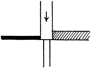
Fig. 25.
The irrigation registers of course show how the irrigation of the different channels is going on from year to year and if changes in the turns become necessary they can be effected.
After the water has entered the watercourses the canal officials have nothing to do with its distribution.[126] The people arrange among themselves a system of turns, each person taking the water for a certain number of “pahars”—a pahar is a watch of three hours—or fractions of a pahar. The zilladar can however be called in by any person who has a dispute with his neighbour. If the matter is not settled the person aggrieved can lodge a formal complaint and a canal officer then tries the case, and if necessary punishes the offender.
In former days it was usual, in some places, for no regular turns to be fixed for the distributaries, orders being issued regarding them from time to time. The weak point about any such plan is that in the event of the controlling officer delaying, owing to any accident, to issue an order, no one knows what to do. Orders were also sometimes issued to zilladars giving them discretionary powers in distribution. No one would now issue such orders. The essential principle is to remove power from the hands of the subordinates. The working of the main channels by turns and the construction of outlets of such a size that they never require closure, has resulted—in places where such matters are attended to—in the absolute destruction of such power.[32] The only way in which a zilladar can injure anyone is to say that water is not in demand. This would however result in damaging the whole of the villages in his charge. He is not likely to do this.
[32] In the printed form lately in use in the Punjab for reports on zilladars, one of the questions asked is whether “his arrangements” for the distribution of water are satisfactory, as if that was still considered to be the zilladar’s business.
In case the supply is wholly or partially interrupted owing to a breach or an accident at the headworks, or other cause, one particular branch or distributary may[127] lose its turn or part of it. If its loss is not great it may be best to allow the turns to take their usual course, but otherwise they should be temporarily altered in such a way as to compensate the channels which have suffered.
On inundation canals the water at a regulator is sometimes headed up,—all branches being partially closed—in order to give more water to outlets in the upstream reach. There are even some regulators—or rather stop-dams—constructed solely for this purpose at places where there is no bifurcation of the canal or distributary. Any such heading up should be planned out beforehand and days for it fixed, and also the gauge reading. If the water, without any heading up, rises to the needful height on the gauge, nothing has to be done. There are also places on inundation canals where the land is high and is only irrigable during floods. At such places it is usual, on some canals, to allow the people to make cuts in the bank when the water attains a certain height. Owing to the high level of the country, nothing in the nature of a breach can occur. In one canal division where the above arrangement was in force, the people used to send applications to the Executive Engineer for leave to cut the banks. This resulted in much delay. A list was prepared showing exactly where the banks might be cut, the people were informed and the formalities were much reduced.
An existing canal or distributary may need remodelling for various reasons, and in various degrees. If the velocity is too high and the bed has scoured, or the sides have fallen in, it may be necessary to raise the crests of falls, or to construct intermediate weirs, or to widen the channel and reduce the depth. If the command is not good it[128] may be necessary to regrade the channel. If silt deposit occurs, the cross-section of the channel may have to be altered, to give a better relation between D and V. If there is surplus water, extensions or enlargements of channels may be desirable and these can sometimes be undertaken to a moderate extent merely by restricting a somewhat too lavish supply to existing distributaries. If the water level is dangerously high it may have to be lowered, or the banks raised and strengthened. Sometimes it is desirable to cut off bends either to shorten the channel and gain command or because the bends are sharp and cause falling in of the banks or, if numerous, silting. In all cases the general principles are the same as for entirely new projects, but certain details require consideration.
The distributaries of the older canals were constructed before Kennedy’s laws regarding silting were known, and it has been necessary to remodel many of them. In some cases the gradient was wrong, in others the cross-section.[33] In some cases a distributary ran in rather low ground, and it was proposed to abandon it and construct a new one on high ground. It was however pointed out by Kennedy (Punjab Irrigation Paper No. 10, “Remodelling of Distributaries on old Canals,”) that irrigation had become established along the course of the distributary, that most of it would remain there and that a new alignment would result in increased length of watercourses. Such distributaries have therefore been allowed to remain very much as they were.
[33] The difficulty of reducing the size of a channel which is too large is well known and has been discussed in River and Canal Engineering, Chapter VIII. It is there explained that a moderate reduction of width can be effected by “bushing,” but that for great reductions, groynes or training walls are necessary. When the bed of a distributary is too low it has been suggested that it could be raised by filling in earth in each alternate length of 500 feet, and leaving the rest to silt, but this would be expensive.
[129]
Remodelling should not be considered piecemeal, but regard should be had to the whole channel. When a distributary is remodelled the outlets should of course be dealt with as well as the channel. The chief thing to consider is not whether the channel as it exists is exactly as it was originally designed to be, but how it is doing its work and what kind of alteration it needs. Even when a simple silt clearance or berm cutting of a channel has to be undertaken, the work need not always consist in blindly restoring the channel to its original condition. It may be both feasible and desirable to remodel it to a slight extent, lowering the water for instance in reaches where the outlets draw off very good supplies and thus benefiting less fortunate reaches lower down.
The irrigation boundaries of the extended or remodelled channel should as far as possible follow drainages, but these are not always important or pronounced. The actual irrigation boundaries should be shown and also those of any neighbouring channels of other canals, and any suitable adjustments should be made.
Regarding the percentage of area to be irrigated, it has already been stated that one canal or distributary irrigates a far higher percentage than another. Generally when there is a high percentage in any tract, it is undesirable to cut it down unless it has very recently sprung up to the detriment of other tracts. In some remodelling projects a uniform percentage is taken on the whole area including both new and old irrigation. This plan is suitable when the percentage of old irrigation is not very high. In other cases the old irrigation[130] to be provided for may be taken as the maximum area actually irrigated, a little being perhaps added for extensions. If the irrigation of considerable areas of jungle tracts is contemplated and if these consist of numerous small patches, a further percentage can be added for them. If there are large jungle tracts they can of course be dealt with separately and any suitable percentage adopted for them. The percentage for each portion of a remodelling project is not necessarily the same.
If the discharge of a channel is increased, the waterways of bridges may need increasing. This can often be done (Chapter II., Art. 12) by making a floor at a low level. Or the waterway may be allowed to remain small, the floor being added at the bed level and the bridge then becoming an incomplete fall, (page 87). The fall in the water surface, though small, can be recognised and shown on the longitudinal section.
In remodelling schemes, the longitudinal section should give all possible information. It should show not only the levels of bed and banks, but the F.S. levels (in blue figures) above and below all falls or regulators, and the levels of floors and waterways of bridges. The plan should show all watercourses and the “chaks” or areas assigned to them.[34] On each chak the actual average irrigation can be shown in blue figures and the proposed irrigation in red. The “draw-off” for each proposed outlet can then be shown on the longitudinal section. The area actually irrigated, as shown on the[131] map, should in each case be the mean of at least three years, and if possible of five years. The number of years should be mentioned in a note on the map. Cross-sections of channels should always be drawn to natural scale, and not with the horizontal scale differing from the vertical.
[34] The field maps mentioned on page 101 are prepared to a very large scale and show all watercourses. The maps should always be corrected up to date by the patwaris. The chak maps which are on a smaller scale—say 4 inches to the mile—can thus be kept correct.
When a channel is remodelled, the remodelling of the outlets may consist in alterations of the number or sites or in alterations of their sizes.
Regarding the former, a map should be prepared showing all watercourses, chaks and contours.[35] On this map new lines for the watercourses can be shown, the principles enunciated in Chapter II., Art. 9, being generally followed, but in such a way as to utilise existing watercourses and outlets as far as possible. The work often consists in the abolition of a certain number of watercourses, when these are too close together and run parallel to one another. There may, however, be little gain in amalgamating two such watercourses if they serve two different villages. There is nothing to prevent the people from dividing the watercourse into two as soon as it gets away from the canal, and they are likely to do this in many cases. When one branch has a flatter slope than the other it would lose command if it took off further down. The people on the steeper branch might not agree to using the flatter one because of silt trouble, or increased height of embankment. In a new project it is not difficult to get the people to do what is needed, but[132] when once irrigation has become established it is often difficult to get suitable changes made. The advantages of amalgamating watercourses, though appreciable, have been a good deal exaggerated. The chief advantage is gained by reduction in the sizes of outlets. Then, however many branches the watercourse may have, they can only run in turns and not all together. It may happen that two watercourses, though taking off near one another, run in different directions and that the chaks are of suitable shapes and sizes. In such a case the only advantage of amalgamating is that it saves an outlet in the canal bank. No saving in the length of watercourse will be effected because there will be a bifurcation as soon as the watercourse leaves the canal boundary. If both outlets are of suitable design and proper size or require only slight alteration, both can remain but otherwise amalgamation can be effected. In some cases amalgamation might give a discharge greater than that usually allowed for an outlet but this need form no obstacle. The chief reason for limiting the discharge is the alleged inability of the farmers to manage a large channel. This matter is exaggerated as already stated (page 74). In the case under consideration it obviously makes no difference whether there are two watercourses each discharging 5 c. ft. per second, or one discharging 10 c. ft. per second, and immediately dividing into two. Very small watercourses should, when possible, be joined to others but if there is no other near enough they must generally remain, however small they may be.
[35] In small remodelling schemes the lines of existing watercourses show how the country slopes, and a contour plan is not a necessity.
Regarding the alterations in sizes of outlets, whether or not there are alterations in their number and position, information as to the actual duties on the watercourses[133] should be obtained. The discharge of the watercourses should be observed several times and added up and checked with the discharge of the distributary. The areas irrigated are known from the irrigation register. If the duties are abnormal the causes can be gone into, and a judgement can be formed as to how far they will remain in existence, and whether any watercourse is often kept closed. If so the outlet is too large. The duties, modified so far as may seem desirable, can be used for calculating the sizes of the remodelled outlets. But alterations of the sizes after a year or two years’ working will probably be necessary. The above procedure is also applicable to a case where the old watercourses had no masonry heads but were merely open cuts as on some inundation canals.
A common case is that in which the channel is not remodelled—or at least its water level remains very much as before—but merely the outlets are altered in number, position or size, or in any or all of these. If the land irrigated by an outlet is high, the irrigation may be far short of what was expected, and the size of the outlet may have to be increased or its site shifted, generally upstream. This is often done at the request of the people, and at their expense.[36]
[36] On some of the more modern canals the people are not allowed to pay for outlets, so that no question of ownership can arise.
Old outlets should always be removed when superseded by others. Otherwise they are apt to be reopened or claims set up regarding them.
Near the tail of a channel the discharge of an outlet may be an appreciable fraction of that of the channel. In such a case the adjustment of the size of the outlet, and[134] that of the channel or of any weir or fall in the channel, should be considered together, the irrigation on the outlet and that on the channel downstream of it being compared. And similarly as to the sizes of any two or more tail outlets. Such outlets are sometimes left without masonry heads on the ground that this injures no one. It may injure an outlet upstream of them by drawing down the water. Tail outlets often need constructing or reducing in size to raise the water level in the reach upstream of them.
Whenever the size of an old outlet is altered the design should be altered if unsuitable. The parapets should be brought into proper line, the roadway corrected, the floor level adjusted and any splayed wing walls abolished. If the outlet is skew it should be made square. All this should also be done to all old outlets or heads of minors even if the sizes are correct, whenever remodelling of outlets on any channel is undertaken.[37]
[37] Wherever an outlet is built or altered, a template, made to the exact size of barrel required, should be supplied to the subordinate in charge of the work.
It was stated in Chapter II. that the construction of masonry outlets on a distributary is not usually a final settlement of the matter. In many cases a proper proportion of water does not reach the tail. Even in such a case matters have occasionally been left alone, or the old and pernicious system of closing the upper outlets has been resorted to. In such circumstances the irrigation of a group of tail villages will be found to be less than that of a group higher up, the people to some extent acquiescing in the old idea that a tail village must be a sufferer. Government, or at least the Irrigation Department, has[135] no particular direct interest in the matter. The total area irrigated, will probably be very much the same in any case. But an engineer who takes an interest in this part of his work will not allow matters to remain long in the state described. He will, of his own accord, adjust the outlets and equalise, as far as possible, the irrigated percentages. The people will disturb matters to some extent by enlarging watercourses, but there is a limit to this and it can be met by an occasional reduction of an outlet. A distributary, when once its outlets have been carefully adjusted, attains to something approaching perfection in its working. Any excess in the supply is taken partly by the upper outlets but part of it gets to the tail. Similarly any deficiency in the supply is distributed over the channel. The outlets which have a poor command and small head are most affected in either case. On the whole they do not lose or gain more than the others. The working of such a distributary causes great satisfaction to the engineer and not the least ingredient in this is the knowledge that he has wholly destroyed the power of his native subordinate.
In an inundation canal division in the Punjab, some dozen distributaries, varying in length from 5 to 28 miles, and with discharges ranging up to 300 c. feet per second, were dealt with as above in one season. The engineer in charge being specially desirous that sufficient water should reach the tails, reduced the sizes of some outlets too much. When an outlet of 1 or 2 sq. feet has to be reduced to a small fraction of its size it is not easy to say what the fraction shall be. Water reached the tails of all the channels in sufficient quantity, in some cases in rather more quantity than was necessary.[136] When the irrigation register was examined, it was found that the general results were entirely satisfactory. In a small proportion of cases outlets had irrigated too little and had to be re-enlarged somewhat. After a second season hardly any changes were needed. When any silt clearance or berm-cutting seemed necessary the irrigation register again came into play. If, for instance the tail outlets, as a whole, were receiving too little water, enlargement of the upstream reaches was effected with consequent lowering of the water level there.
In the case above described the channels flowed for only five months in the year. Some of them silted a good deal but as this silting was roughly the same every year, it did not greatly affect the question of outlet sizes. On a perennial distributary of which the head reach silts during part of the year and scours during the other part, a proper distribution of supply by adjustment of outlet sizes alone may be more difficult. If the silt was frequently cleared, this would cause needless expense and interference with irrigation. In cases where the distributary is not run constantly, something can be done by attending to the regulation. When there is silt in the head reach, the discharge can be reduced and the period of flow proportionately increased. The lowered water level reduces the supplies of the upper outlets, and increases the discharges of those lower down. Moreover the periodical silting and scour are not always serious. Also it is not essential that the supply to each watercourse should be exactly the same every year. There are always good and bad seasons. It is sufficient if a watercourse is not allowed to suffer on the whole, and is never allowed to suffer much. There is no doubt that it is possible to deal satisfactorily in the above[137] manner with very many distributaries. It is frequently reported that “difficulty is experienced in getting water to the tail.” This is owing to timidity in reducing the sizes of outlets. The suitable plan is to reduce them to such an extent as to cause a proper supply to reach the tail and then, if necessary to enlarge some. It has been already remarked that only a short length of the barrel need be altered. The cost of this is very small. The real difficulty in the case is not the impossibility of securing good results, but the impracticability, in many cases, of securing the constant attention which the procedure demands.[38]
[38] See also Chapter V. Art 3.
At the headworks of a canal there is a permanent staff of men who work the gates and look after the works. They assist in discharge observations and in reading the gauges, and they may have to take soundings in the river to see what changes are taking place. Some one is on watch day and night and reads the gauges at frequent intervals. The officer in charge occasionally inspects the works at night without notice. Detailed rules regarding the above matters, and any others that are necessary owing to special local conditions, are drawn up. Sometimes there is difficulty in getting the staff to attend properly to the regulation of the supply in the canal at night. Probably some “tell-tale” watches would be useful. They would at least show the times at which the men concerned went to the gauges or other points.
At the headworks, and at all important regulators, a stock of concrete blocks should be kept ready for the execution of any urgent repairs.
[138]
Regarding the ordinary maintenance work on the channels, details are given in Appendices B and C. Appendix D, reprinted from Punjab Rivers and Works, contains rules for watching and protecting any banks or embankments which require it.
Silt clearances and berm cutting of channels have been mentioned in Art. 1. Special attention should be given to the accurate ranging of the centre line. Otherwise the channel may become crooked. The great defect in the earthwork ordinarily met with in the banks of canals and distributaries is that the clods are not broken. In consequence of this new banks are extremely liable to breach, and much trouble and expense result. Sometimes a dam is thrown across a new distributary, and the channel upstream of it is gradually filled with water, the bank being watched and leakages made good. The dam is then shifted to a place further down. In this way the banks are consolidated.
When a distributary is closed for silt clearance or other work, if the head regulator has planks and a double set of grooves, it is possible to stop all leakage by filling in earth between the two sets of planks and ramming it, but otherwise it is necessary to construct an earthen dam just below the regulator. Upstream of the dam the water, owing to the leakage through the planks, gates or needles, rises to the same level as the water in the canal. Native subordinates have a remarkable aptitude for allowing such dams to break while the work in the distributary is in progress or before it is measured. Now and then the dam is wilfully cut. The remedy is to make the dam of proper strength—the top should be 8 feet wide and a foot above the water,—and to have it watched day and night.
[139]
At a bend in a channel there is often a silt bank next the convex bank, and a hollow near the concave bank. The average bed level is probably very much the same as in the straight reaches. Removal of the silt bank is unnecessary, and if removed it quickly forms again.
Any length of channel in which the depth of silt to be cleared is small, say ·50 foot in a large channel and ·40 foot in a small one, should not be cleared, provided its length is considerable (say 1,000 feet), and that it is not close to (say within 3,000 or 2,000 feet from) the head of the channel. Estimates should be prepared accordingly, the shallow digging being struck out. Clearing a small depth of silt merely gives contractors a chance of cheating by scraping the bed.
If the watercourses at the tail of a distributary are silted, the people should be pressed to clear them. Otherwise there will be heading up of the water of the distributary, and silt deposit may result.
When a channel is scoured, any regulator in it can be kept partly closed so as to reduce the surface slope in the reach upstream of the regulator and encourage the deposit of silt. A table should, in such cases, be drawn up giving the gauge readings to be maintained at the tail of the reach corresponding to given readings at the head.
Various methods of protecting banks are described in River and Canal Engineering, Chapter VI. The growing of plants on the inner slopes of channels whose sides fall in, needs special attention. Some remarks on this are given in Punjab Rivers and Works, Chapter II., Art. 3. A specification for bushing is given in Appendix E of this volume.
[140]
A Subdivisional Officer generally receives a steady stream of applications from members of the irrigating community regarding—among other matters—outlets or watercourses. Generally these applications are made over to the zilladar to be reported on. In a large number of cases the applicant states that the irrigation of his land or “holding” is not satisfactory, or has fallen off, and sometimes he asks that it may be transferred, wholly or in part, to another watercourse which he thinks will give a better supply. In all such cases, and in some others, the first requirement is a statement of the irrigation figures. The irrigation register gives only the total for the watercourse. A printed form should be prepared with spaces for showing the name of the distributary, villages, watercourses, holdings and applicants concerned, and the nature of the application. Below this is a form, prepared somewhat as shown below. When this form is filled in, the state of affairs can at once be seen and much trouble is saved. The zilladar obtains the figures from the old field registers. The amount of detail required as to the applicant’s lands depends on the nature of his application. If it deals with only part of his land the other parts should also be shown. He may for instance be giving a disproportionate share of water to one part. If a transfer to another watercourse is asked for, the figures for that watercourse are also required.
| Areas in Acres. | Applicant’s Holding. | Total of Watercourse. |
Total of Distributary. |
||||||
|---|---|---|---|---|---|---|---|---|---|
| Total. | |||||||||
| Culturable commanded. | |||||||||
| Net irrigated |
- | 19...-19... | |||||||
| 19...-19... | |||||||||
| 19...-19... | |||||||||
| Total of 3 years | |||||||||
| Average | |||||||||
| Per cent. of culturable commanded |
|||||||||
[141]
If an application refers to a whole watercourse, the Subdivisional Officer can frequently, with the aid of an irrigation register and a set of chak maps, both kept up to date, dispose personally of the case. A good plan is to settle cases when on tour near the place concerned, the applicant and the zilladar being present as well as any other persons concerned. A certain number of cases have to come up again on the following tour, but all are settled in less time than is occupied if the papers go up and down between the Subdivisional Officer and the zilladar, the “file” of papers in any particular case being constantly swollen by reminders from the applicant.[39] Moreover, the applicants know that their views are known to the Subdivisional Officer. If the outlets on a channel need a general remodelling, such applications as those under consideration receive attention in connection with the scheme. Otherwise all the applications concerning one distributary can be considered together. If, however, a case is pressing, or the steps to be taken obvious, it can be settled without reference to any other case.
[39] The plan of personal settlement is distasteful not only to the subordinates, but to the munshi who has charge of the “vernacular files.” Ordinarily he can delay a case, or manipulate it to some extent.
The general arrangements for the “revenue” work[142] or assessment of water rates have been stated in Art. 1. In the Punjab the remissions for failed crops are a source of trouble. In some districts the failed areas are small, and no particular trouble arises, but in other districts such areas are often very large. On perennial canals the crop inspection is done by the zilladars, on most of the inundation canals by the subordinates of the District Magistrate.[40] In both cases the amount of labour involved is enormous, and the corruption to which the system gives rise is also enormous. In the case of the inundation canals the superior staff of the District Magistrate nominally make checks, but the time at their disposal is wholly inadequate. In the case of the perennial canals the Canal Engineers are able to exercise considerable checks, but nothing like enough. In fact the state of a crop and the proportion of the charge on it which should be remitted is a difficult thing to judge, even if the subordinates were without guile. It is understood that a new and statesmanlike system is now to be introduced, the District Magistrate deciding, in consultation with the Executive Engineer, whether the season is such as to call for any general remission for each kind of crop, and, if so, to what extent. The proportion to be remitted in that crop is then to be fixed, and it is to be the same for every one.
[40] Officially called the “Collector” in some provinces, and “Deputy Commissioner” in others.
It has been mentioned that some irrigation is effected by lift. The simplest form of lift is a horizontal pole which rests, not far from its thick end, on a support. From its thick end is suspended a bucket, and from its thin end a weight. A man lifts the thin end so that the bucket then dips into the water and is filled. Pulling[143] down the thin end he raises the bucket and empties it. A greatly improved lifting apparatus is the Persian wheel which is vertical and has slung from it, like the buckets of a dredger but moving vertically, a number of earthen jars, which scoop up the water. As each jar passes over the top of the wheel it assumes a horizontal position, discharges its water into a shoot, and descends in an inverted position. The wheel is moved by a simple cog-wheel arrangement actuated by a bullock which is driven round and round in a circular track. The Persian wheel is used for lifts of any height. The lift from a canal watercourse is a few feet, that from a well may be 50 feet or more.
Most persons consider that a system of charging for water by volume would be a very great advance on present methods. It has been said that if the water were wasted it would be difficult for the cultivators to bring home the responsibility to any individual. This objection does not seem to have great force. Every individual would have a direct interest in economising the water, and any cultivator who was habitually careless would soon be detected by the others. In all probability the result would be a great improvement in the duty of the water. But the justice of any very rigid system of charging by volume is somewhat doubtful. The great difference in the duty of water on different watercourses has been mentioned more than once. Many of the causes of this are beyond the control of the farmers, and it would probably be necessary to charge reduced rates to some of them.
[144]
[41] See Report on the Project Estimates of the Upper Jhelum, Upper Chenab, and Lower Bari Doab Canals.
Fig. 26 shows part of the Punjab. The areas marked L.J., L.C., U.B.D., and S.C. are already irrigated by the Lower Jhelum, Lower Chenab, Upper Bari Doab[42] and Sirhind Canals. The areas which it is considered very desirable to irrigate,[145] and which are provided for in the Triple Canal Project, are marked U.J., U.C., and L.B.D., and the new canals are shown by dotted lines. Other areas needing irrigation lie on the left bank of the lower part of the Sutlej, partly in British territory and partly in Bahawalpur State, and one area,[43] of scant rainfall and subject to occasional famine, lies immediately South of the Sirhind Canal tract. There is also a very large area between the Indus and the Jhelum, and it has been proposed to irrigate it from the Indus, but on account of the presence of sand-hills the project is not likely to be so useful as others, and it is held in abeyance. Perhaps a small canal may be constructed, as a tentative measure, to irrigate part of the tract.
[42] Doab means “two waters,” or the tract between two rivers. The names of the three Doabs under consideration are formed from those of the rivers. They are called the Jech (Jhelum-Chenab), Rechna (Ravi-Chenab), and Bari (Beas-Ravi) Doabs.
[43] It would be very expensive to bring water for this tract from the Beas and across the Sutlej.
The winter discharges of the rivers (available for the rabi crop) after the existing irrigation has been supplied, are as follows:
| Indus, | 9,434 | c. feet per | second | (minimum) |
| Jhelum, | 6,800 | „ | „ | (average) |
| Chenab, | Nil | |||
| Ravi, | Nil | |||
| Beas, | 4,000 | „ | „ | (minimum) |
| Sutlej, | Nil | |||
In summer all the rivers have discharges (available for the kharif crop) far exceeding any requirements. It was at one time proposed to supply the Lower Bari Doab Canal from near the junction of the Beas and Sutlej, and a project for this was prepared, but before it was sanctioned a proposal was put forward to convey[146] the surplus water of the Jhelum eastward across the Chenab and Ravi. This valuable suggestion was made by Sir James Wilson, who was then Settlement Commissioner of the Punjab, and, independently, by the late Colonel S. L. Jacob, R.E., who had been a Chief Engineer in the Punjab. The proposals were, however, to take off the supply from the Jhelum lower down than as now arranged in the Triple Project. This would have resulted in only a partial utilisation of the Jhelum water, in mutilation or heavy alterations to the existing Lower Jhelum and Lower Chenab Canals, in for ever debarring the Upper Jhelum and Upper Chenab tracts from irrigation, and in a very costly scheme for the Lower Bari Doab Canal.[44]
[44] Colonel Jacob made his suggestion when in England after retiring from India, and when he had no levels to guide him.
The Triple Project as prepared by Sir John Benton, K.C.I.E., recently Inspector General of Irrigation in India, gets over all the above objections. The Upper Jhelum Canal is to irrigate the country which it traverses, and in the winter, when the supply in the rivers is restricted, it is to deliver into the river Chenab, above the weir at the head of the Lower Chenab Canal, a discharge equal to that drawn out higher up by the Upper Chenab Canal.[45] Thus the Lower Chenab Canal, which at present draws off the whole of the water of the Chenab in winter, will not be injuriously affected in any way. The Upper Chenab Canal after irrigating its own tract is to deliver a large volume of water into the Ravi. The water will be taken across that river by a level[147] crossing, and supply the Lower Bari Doab Canal. The water brought into the Sutlej from the Beas will remain available for irrigation on the left bank of the Sutlej, or possibly for the dry tract South of the Sirhind Canal area. This fine scheme presented many difficulties and is necessarily costly. The water has to be conveyed a great distance, and there will be much loss by absorption. The Ravi crossing will be a very heavy work. The Upper Jhelum Canal has to be taken by a circuitous course round a range of hills, and to cross numerous heavy torrents. The scheme will, however, prove remunerative in spite of immense difficulties as to labour, caused by the outbreak of plague in the Punjab a few years ago.
[45] The Indus is at a higher level than the Jhelum. The latter river runs in a comparatively deep valley, and it is unfortunately impossible to convey the water of the Indus across this valley.
The figures on which the discharges in the Triple Project are based form a useful and interesting object lesson. In order to obtain sufficient water in the winter, it is necessary to reduce the rabi supply to the existing Lower Jhelum Canal. The figure above given for the Jhelum indicates the supply available after the reduction. More water will be supplied to the Lower Jhelum Canal for the kharif, the canal being enlarged for this purpose, and its total irrigation will be unaffected. The proportion of the culturable commanded area to be irrigated in the new tracts is 75 per cent., but from this the area irrigated by wells in the Upper Jhelum and Upper Chenab tracts is deducted. On the Lower Bari Doab Canal there is little well Irrigation, but there are some low-lying tracts near the rivers, and of these only 50 per cent. will be irrigated. The kharif and rabi areas are in all cases to be equal.
[148]
The areas to be irrigated in each crop are as below—
| Lower Jhelum Canal | 383,091 | acres |
| Upper Jhelum Canal | 172,480 | „ |
| Upper Chenab Canal | 324,184 | „ |
| Lower Bari Doab Canal | 441,264 | „ |
| Total | 1,321,019 | „ |
The total, excluding the existing Lower Jhelum Canal, is 937,928 acres. With an equal area in the other crop, the new annual irrigation amounts to 1,875,856 acres.
The kharif duty is taken as 100 acres at the distributary heads, this being about the figure actually obtained on the Lower Chenab and Upper Bari Doab Canals, and the required kharif discharges at the distributary heads are:
| Lower Jhelum | 3,821 | c. feet per | second | |||
| Upper | „ | 1,725 | „ | „ | ||
| „ | Chenab | 3,242 | „ | „ | ||
| Lower Bari Doab | 4,413 | „ | „ | |||
| Total, excluding Lower Jhelum |
- | 9,380 | „ | „ | ||
The losses of water in canal and branches have been found to be, on the Upper Bari Doab Canal 10 c. feet per second, and on the Lower Chenab Canal 8 c. feet per second, per million square feet of wetted area respectively. The conditions of the latter canal most resemble those on the new canals under consideration. The losses calculated on the wetted areas of the channels, as designed, at 8 c. feet per second per million square feet, are as follows, in c. feet per second:
[149]
| Lower Jhelum Canal | 624 | - | 1,288 | |
| Upper Jhelum Canal | 664 | |||
| Upper Chenab Canal | 1,161 | - | 2,126 | |
| Lower Bari Doab Canal | 965 | |||
| Total | 3,414 | |||
But in dry years the canals will be worked in rotation during the rabi, the Upper Chenab and Lower Bari Doab Canals being worked together, and the Upper Jhelum and Lower Jhelum together.
When the Lower Jhelum Canal is closed, in course of rotation, the Upper Jhelum Canal will still be flowing, and the loss in it, 664 c. feet per second, has to be added to the figure (2,126) given above, thus bringing up the loss to 2,790 c. feet per second.
In order to ascertain what the state of affairs will be in the rabi, the statistics obtained on the Lower Chenab Canal were examined. These show that the rabi duty at the distributary heads on that canal is 206 acres. On the Upper Bari Doab Canal the duty at the distributary heads is 263 acres, but 11 per cent. of the area receives only “first waterings.” The duty based on the remaining area is 234 acres. But the above duties are only attained by running higher supplies in October and March than during the intervening four months of the crop. The following remarks and figures are taken from the Report on the Project Estimates:—
“The statistics of working of distributaries of the Chenab and Bari Doab Canals give the average discharges shown in the following table for the three years ending with 1903-04. The losses by absorption are calculated on the wetted areas for the different rotational periods. The average discharge less absorption is the supply which reached the heads of the distributaries.
[150]
CHENAB CANAL.
| Particulars. | Period. | Aver- age. |
||||||
|---|---|---|---|---|---|---|---|---|
| October 1st-15th |
October 16th-31st |
No- vember |
De- cember |
January. | February | March. | ||
| Cusecs. | Cusecs. | Cusecs. | Cusecs. | Cusecs. | Cusecs. | Cusecs. | Cusecs. | |
| Average supply entering head of canal | 10,196 | 10,285 | 7,788 | 5,593 | 5,127 | 5,500 | 6,603 | 6,809 |
| Deduct absorption | 1,633 | 1,633 | 1,250 | 1,053 | 1,032 | 1,171 | 1,433 | 1,262 |
| Supply at distributary heads for 1,155,685 acres, the average Bari area | 8,563 | 8,652 | 6,538 | 4,510 | 4,095 | 4,329 | 5,170 | 5,546 |
| Proportional supply for 1,164,595 acres | 8,631 | 8,721 | 6,590 | 4,576 | 4,128 | 4,364 | 5,211 | 5,591 |
| Add absorption for new projects | 3,414 | 3,414 | 2,139 | 2,139 | 2,139 | 2,139 | 3,414 | 2,564 |
| Supply required for new projects at heads of canals | 12,045 | 12,035 | 8,729 | 6,715 | 6,267 | 6,503 | 8,625 | 8,155 |
[151]
“The average discharge given by the third line is 5,546, and the average area being 1,155,685 acres, the duty at the heads of distributaries was 208.
“The area 1,164,595 is the perennial rabi irrigation of the new projects, the area 156,424 acres, receiving only first waterings, being omitted to admit of a fair comparison, and is only 1 per cent. under the average attained on the Chenab Canal in the three years for which the table is prepared.
“The absorption added for the two first periods is on the supposition that all the canals are open throughout October and March, tatilling[46] with an average absorption loss of 2,139 cusecs[47] being in force during the other four months. The last line of the table shows the average Rabi discharge required by the new projects at the heads of canals, inclusive of all losses calculated on the Chenab Canal basis of a duty of 208 acres per cusec obtained at the heads of distributaries.
[46] “Tátíl” is the Indian word for rotational closure.
[47] “Cusec” is used in India for c. ft. per second.
“The Bari Doab Canal statistics furnish the means of the adequacy of available supply being gauged. The following table furnishes particulars for the average supply of water entering the head of the canal for the five years 1898-99, 1899-1900, 1901-02, 1902-03, 1903-04. The figures for the year 1900-01 are omitted, as it was a very abnormal one of very plenteous supply and heavy rainfall:—
“The average irrigation for the five years in question was 442,302 inclusive of 11 per cent. which only receives first waterings. This divided by the average supply, 1,685, entering the head of a canal gives a duty of 263 acres per cusec at the heads of distributaries.
[152]
BARI DOAB CANAL.
| Particulars. | Period. | Aver- age. |
||||||
|---|---|---|---|---|---|---|---|---|
| October 1st-15th |
October 16th-31st |
No- vember. |
De- cember. |
January. | February. | March. | ||
| Cusecs. | Cusecs. | Cusecs. | Cusecs. | Cusecs. | Cusecs. | Cusecs. | Cusecs. | |
| Average supply entering head of canal | 3,769 | 2,896 | 2,170 | 1,755 | 1,622 | 1,916 | 2,909 | 2,284 |
| Deduct absorption | 599 | 599 | 599 | 599 | 599 | 599 | 599 | 599 |
| Supply at heads of distributaries (a) | 3,170 | 2,297 | 1,571 | 1,156 | 1,023 | 1,317 | 2,310 | 1,685 |
| Corresponding supply for new schemes 3 × figures line (a) | 9,510 | 6,891 | 4,713 | 3,468 | 3,069 | 3,951 | 6,930 | 5,055 |
| Add absorption for new projects | 3,414 | 3,414 | 2,139 | 2,139 | 2,139 | 2,139 | 3,414 | 2,564 |
| Supply required for new projects at heads of canals | 12,924 | 10,305 | 6,852 | 5,607 | 5,208 | 6,090 | 10,344 | 7,619 |
[153]
“The rabi irrigation of the new projects is 1,321,019 acres,[48] and this divided by 442,302 gives approximately the multiplier 3 referred to at (a) in the above table.
[48] Including the Lower Jhelum.
“The figures given in the above table and in the foregoing remarks relate to the aggregate of the areas in the rabi which receives a perennial supply and which only receives first and last waterings. On the Upper Bari Doab Canal the rabi which receives perennial irrigation is averagely 393,649 acres; the average supply of 1,685 cusecs gives on this area a duty of 234 acres per cusec at the heads of the distributaries.
“In the case of the three projects the aggregate rabi area receiving perennial irrigation as shown by the table, paragraph 21[49] supra, is 1,164,595 acres: this is 2·96 times 393,649; so that the proportional supply required on this basis would be slightly less than that given by the multiplier 3 in the above table.
[49] Not printed. The area is the total rabi area less the area which is to receive only first waterings.
In explanation of the difference of the duties:—
| Lower Chenab Canal | 208 | acres per cusec, |
| Upper Bari Doab Canal | 234 | ditto, |
it may be stated that the Lower Chenab Canal is a comparatively new work, and that the duty has been steadily rising and, with the perfect watercourse system, may be relied on to reach the Upper Bari Doab Canal 234 acres per cusec in the course of time for water arriving at the heads of distributaries.
*******
“27. Summary of conclusions as to sufficiency of supply.—The following table shows all the foregoing results in a form readily admitting of comparison:—
[154]
| Particulars. | Period. | Average supply in river. |
Deduct loss by absorp- tion. |
Supply at heads of distribu- taries. |
Duty calculated on 1,321,019 acres, the gross rabi area. |
Duty calculated on 1,164,595 acres, the perennial area. |
||||||||||||||||||||||||
|---|---|---|---|---|---|---|---|---|---|---|---|---|---|---|---|---|---|---|---|---|---|---|---|---|---|---|---|---|---|---|
| 1st to 15th Octo- ber. |
16th to 31st Octo- ber. |
No- vem- ber. |
De- cem- ber. |
Janu- ary. |
Febru- ary. |
March. | ||||||||||||||||||||||||
| Cusecs. | Cusecs. | Cusecs. | Cusecs. | Cusecs. | Cusecs. | Cusecs. | Cusecs. | Cusecs. | Cusecs. | |||||||||||||||||||||
| Average Supplies available. | ||||||||||||||||||||||||||||||
| Very favourable years 1 in 4 | - | 21,400 | 15,150 | - | 11,850 | 8,626 | 11,200 | - | 13,100 | 21,250 | - | 11,811 | 3,414 | 8,397 | 158 | 139 | ||||||||||||||
| (13.063) | (13,063) | (13,063) | (13,063) | |||||||||||||||||||||||||||
| Ordinary years 2 in 4 | - | 13,900 | - | 11,850 | 10,000 | 7,400 | 7,600 | 9,100 | - | 16,500 | - | 9,946 | 2,989 | 6,957 | 189 | 167 | ||||||||||||||
| 13,063 | 13,063 | |||||||||||||||||||||||||||||
| Dry years 1 in 4 | 10,150 | 9,100 | 7,275 | 5,950 | 5,610 | 6,100 | 11,345 | 7,651 | 2,564 | 5,087 | 259 | 229 | ||||||||||||||||||
| Minimum of 14 years | 9,710 | 8,003 | 6,624 | 5,810 | 5,563 | 5,163 | 9,791 | 6,968 | 2,458 | 4,510 | 293 | 258 | ||||||||||||||||||
| Requirements on average of Lower Chenab Canal for | 12,045 | 12,135 | 8,729 | 6,715 | 6,267 | 6,503 | 8,625 | 8,155 | 2,564 | 5,591 | 236 | 208 | ||||||||||||||||||
| Requirements on average of Upper Bari Doab Canal for 5 years | 12,924 | 10,305 | 6,852 | 5,607 | 5,208 | 6,090 | 10,344 | 7,619 | 2,564 | 5,055 | 261 | 230 | ||||||||||||||||||
[155]
“The 13,063 shown in brackets represents the parts of the available supply which the canals can carry, the capacity being as follows:—
| Cusecs. | |
|---|---|
| Lower Jhelum Canal | 4,563 |
| Upper Jhelum Canal | 8,500 |
| Total | 13,063 |
“The average supplies and duty figures are based on the 13,063 cusec maximum capacity and not on the larger available supplies written above these figures where they occur.
“The above table goes to show the following:
(i) In order to utilize the large supplies available in the Jhelum River in October and March every year and in some or all of the intervening months in other years, it is advisable to give the Upper Jhelum Canal the large capacity of 8,500 cusecs proposed.
(ii) In favourable and ordinary years, that is, in 3 out of 4, the available supply will be ample, as shown by the low duties of 189 and 167 compared with those obtaining on the Lower Chenab and Upper Bari Doab Canals.
(iii) In dry years, that is, 1 in 4, it will be necessary to attain a duty almost exactly the same as that now obtaining on the Upper Bari Doab Canal.
(iv) That an exceptionally dry year might occur once in 14 years, when the supply would be 10 per cent. short of that required by the average[156] Upper Bari Doab Canal standard of requirements: such exceptional cases should be met by remissions, which will be far preferable to wasting the good supplies of 13 years out of 14.
(v) That the occasional occurrence of dry years makes it inadvisable to attempt a greater proportion of rabi than half of the annual irrigation.”
The Report on the Project estimates gives, for each tract, remarks on its soil, rainfall, height of subsoil water, circumstances as to existing irrigation from wells or small canals and liability to floods. On a consideration of these matters the decision as to the particular parts of the tracts which are to be irrigated and the areas which are, in the rabi, to receive only restricted irrigation, depends.[50]
[50] It is not unusual, in tracts where the level of the subsoil water is high, say within 15 feet of the surface, to have some “kharif distributaries.” These are closed in the rabi. This tends to prevent water-logging of the soil. In the rabi the people lift water from wells. There may also be kharif distributaries in dry tracts if there is no water to spare in the rabi.
In calculating the sizes of the canals, N in Kutter’s co-efficient was taken at ·020. In sharp curves the bed is paved on the side next the concave bank. In high embankments where the soil is sandy the best material is used as a core wall. The torrent works on the Upper Jhelum Canal have been mentioned in River and Canal Engineering, Chapter XII.
Regarding the effect of the new canals on the inundation canals which take off, lower down, from the Chenab below its confluence with the Jhelum, it has for long been the policy to gradually shift the heads of these canals upstream in order to obtain better supplies, or rather to counteract the effect of the abstraction of[157] water for the recently constructed Lower Chenab and Lower Jhelum Canals. Any such abstraction of water has not much effect on the floods, but it has much effect in April and May, when the rivers have not fully risen, and in September, when they are falling.
In order to estimate the effect on the water level of the Chenab—below its junction with the Jhelum—it was necessary to observe discharges of the river, not only in the winter when it is low, but in the summer when it is high. The depth of the water was in some places 40 feet, and the stream 2,000 feet wide. Fortunately the Subdivisional Officer was a native of India and did not much mind the sun. A discharge curve (River and Canal Engineering, Chapter III. Art. 5,) having been prepared, it was possible to construct a diagram with periods of time as the abscissas, the ordinates representing the average known gauge readings on the different dates and another set of ordinates representing the probable discharges. By deducting the discharges which it was intended that the new perennial canals should draw off, it was possible to draw fresh ordinates representing the diminished river discharges and the reduced river gauge readings corresponding to them. It was found that the water level would be lowered by about 1·3 feet in April and May, and by about 1·5 feet in September. It was, however, shown that by shifting the heads of the inundation canals upstream—the gradients of the canals being flatter than that of the river—the effect of the lowering of the water level could, as heretofore, be nullified.
[158]
—The chief improvements which have been under consideration during recent years are three in number. The first is increased economy of water in its actual use in the fields; the second is reduction of the losses by absorption in the channels; and the third is distribution by means of modules.
Regarding the first, it has long been known that the ordinary methods of laying on the water are more or less wasteful. In California, when the water instead of being applied to the surface of the ground, is brought in a pipe and delivered below the ground level, the duty is increased from 250 to 500 acres. In India a field is divided, by means of small ridges of earth, into large compartments. The water is let into a compartment and gradually covers it. By the time the further side is soaked the nearer side has received far too much water. Frequently the water for a compartment, instead of being carried up to it by a small watercourse, is passed through another compartment and this adds to the waste. Also the number of waterings given to a crop is often 5 or 6, when 4 would suffice. Experiments made on the Upper Bari Doab Canal, by Kennedy, showed that the water used in the fields was nearly double what it might have been. The 53 c. ft. shown in Chapter 1, Art. 4, as reaching the fields, were used up when 28 c. ft. would have sufficed. It is not certain[159] that the waste is generally quite as much as the above. It is possible that the restricted supplies might have given smaller yields of crops. More recent experiments made by Kanthack on the same canal give the needless waste as about 25 per cent. The field compartments ought, according to Kennedy, to be 70ft. square, the small branch watercourses being 140ft. apart. It would be better to have still smaller compartments, but this would be rather hard on the people.
At one time Government issued orders, in Northern India, that compartments of 1296 square feet were to be used, and that, otherwise, increased water rates would be charged, but the orders were never enforced. They were thought to press too hardly on the people. Extreme measures for enforcing economy in the use of water in any country are likely to be introduced only when they become absolutely necessary owing to the supplies of water being otherwise insufficient.
—For several years experiments have been going on in the Punjab as to the effect of lining watercourses with various materials. The following conclusions have been arrived at[51]:—
[51] Punjab Irrigation Paper No. 11 C. “Lining of Watercourses to reduce absorption losses. Experiments of 1908-1911.”
(a) The rate of absorption varies greatly, and this is due probably to unequal fissuring of the upper layers of the soil.
(b) The rate of absorption in the three hottest months averaged ·0571 feet per hour, or more than double the rate (·026) in the three coldest[160] months. The difference is ascribed to the greater viscosity of the water when cold.
(c) The average losses with canal water were ·0315 feet per hour, or 8·75 c. feet per second per million sq. feet.[52] With well water the figures were ·1096 and 30·5. The conclusion is that the silt in canal water reduces the losses by more than two-thirds.
[52] This loss of 8·75 c. ft. per second was in water only about a foot deep. This confirms the conclusion arrived at in Chapter I, Art. 4, that the depth of water is not a factor of much importance.
(d) With canal water the average loss decreased by 40 per cent. (from ·0491 to ·0293) in about four years. This was no doubt due to the effect of the silt. With well water the loss at the end of four years (·2293) was nearly four times as great as at first (·0591). This may have been due to removal of the finer particles of soil by the water, but the experiments were made at only one place, and were not conclusive.
(e) With trenches lined with crude oil ¹⁄₁₆ inch thick, or with Portland cement ¹⁄₁₆ inch thick, or with clay puddle 6 inches thick, the “efficiency ratios,” as compared with unlined trenches, are respectively about 4·0, 5·7 and 5·7, the age of the lining being four years. The efficiency ratio is the inverse of the loss. Thus with an efficiency ratio of 3 the loss in the lined trench is 33 per cent. of that in the unlined trench.
[161]
(f) The efficiency ratio in the case of oil may diminish at the rate of 10 per cent. per annum, but in the case of cement and clay puddle it tends to increase rather than to decrease.
Assuming that the efficiency ratios are only 3·0, 4·5 and 4·5, and that the loss in an unlined channel is 8 c. feet per second per million sq. feet, the saving in water by using channels lined with oil, cement and puddle respectively would be 5·33, 6·25 and 6·25 c. feet per second. The average duty of the water at the canal head is about 242 acres, and the average revenue per acre is Rs 3·93. The revenue from 1 c. ft. of water at the canal head is thus Rs 950. Only about half the water reaches the fields (Chapter I., Art. 4), and the revenue from 1 c. ft. of water which reaches the fields is about Rs 1900. The mean of the above two sums is Rs 1425. If 6 c. ft. of water per second could be saved the revenue would be increased by Rs 8,550 per annum.
The cost of lining a million square feet of channel with oil, cement and puddle is estimated at Rs 30,000, Rs 27,500 and Rs 35,000 respectively. Allowance has to be made for the fact that watercourses flow intermittently, and that a lined channel gives no saving when it is not in flow, also that extensions of canals might have to be undertaken in order to utilise the water saved. After making these allowances it is estimated, in the paper above quoted, that the saving effected by lining a million square feet with oil, cement or puddle represents the interest on a capital sum of Rs 69,300, Rs 81,250 and Rs 81,250 respectively, or 2 or 3 times the sums sunk in constructing the linings.
Hitherto the experiments have been carried out on a moderate scale, but extensive operations are now being[162] undertaken on the Lower Chenab Canal, and possibly on others.
In cases where it is not desired to incur much expenditure, it may be a good plan to construct watercourses to a cross section somewhat larger than that ultimately desired. The silt deposited on the bed and sides forms, in most cases, a more impervious lining than the original soil. The same plan can be adopted in the tail portion of a distributary. In a larger channel there would be less certainty that any deposit would take place unless short lengths, at frequent intervals, were excavated to the true or ultimate section, so as to form weirs and spurs; and even these might not stand.
In Italy, in cases where the water naturally contains lime in suspension, the beds of canals have become gradually watertight by the deposit of lime in the channel.[53] In some cases lime has been artificially added. It appears that a considerable period of time is necessary for the process.
[53] Min. Proc. Inst. C. E. Vol. CXVI.
—A module is an appliance which automatically gives a constant discharge through an aperture, however the water level on either the upstream or downstream side of the aperture may fluctuate. In an old and simple form of module there is a horizontal orifice in which works loosely a tapering rod attached to a float. The water passes through the annular space surrounding the rod. If the water level rises, the rise of the float brings a thicker part of the rod to the orifice and reduces the annular space. In another kind of module the water is discharged through a syphon. If the water level alters, the syphon moves in such a[163] way that the head, or difference between the levels of its two ends, remains the same. The great objections to modules are that they are liable to get out of order or to be tampered with. A module recently invented and patented by Gibb[54] has no movable parts, and is not liable to these objections.
[54] For description see Appendix H.
A few years ago the question of the desirability of using modules for the outlets of distributaries in India was raised. The opinions of a large number of the senior canal engineers were called for and considered, and since then the subject has been thoroughly discussed. There are certain inherent difficulties in the way of moduling the outlets of a distributary. Owing, for instance, to rain further up the canal, or to the closure of a distributary owing to a breach in it, the canal supply may increase, and it may be necessary to let more water into the distributary under consideration. Under the present system any excesses of water are automatically taken by the outlets. If all outlets were rigidly moduled they would discharge no more than before the excess supply came in, and the excess supply would all go to the tail of the distributary, and, most likely, breach the banks. To get over this difficulty, the module has to be so arranged that when the water level in the distributary rises to a certain “maximum limit” the module ceases to act as such, and the discharge drawn off from the distributary increases as the water level rises. Again, the discharge of the distributary may at times be considerably less than its full supply. In order that, in such a case, the outlets towards the tail of the distributary may not be wholly deprived of water, it has to be arranged so that[164] when the water level in the distributary falls below a certain “minimum limit” the modules cease to act as such, and draw off supplies which are less the lower the water level. Such supplies are not in proportion to the full supplies of the outlets. It will, however, be shown presently that low supplies need seldom be run. When a distributary, say the upper reach, contains silt, the water level corresponding to a given discharge is higher than before, and care has to be taken that the maximum limit is high enough. At the same time the minimum limit must be so low that it will not be passed when the silt scours out. The difference between the maximum and minimum limits is called the “range” of the module.
In Gibb’s module the above conditions can be complied with. The module is placed outside the bank of the distributary. The water is drawn off from the distributary by a pipe, whose lower edge is at the bed level of the distributary, and delivered from the module into the watercourse through a rectangular aperture at a higher level than that of the pipe. It is possible that, owing to the high level of the aperture, some rolling silt which would otherwise have passed out of the distributary may remain in it. The height of the aperture also prevents the watercourse from drawing off any water at all when the water level of the distributary falls below a certain level, but this objection is not important. An escape weir or notch is provided so that when the water level in the distributary rises to the maximum limit some water overflows into the watercourse. On the whole it appears that all difficulties can be got over, though a good deal of care and[165] precision is necessary in fixing the exact height of the maximum and minimum limits.
The difficulties under consideration will all be reduced if some of the outlets on a distributary are left unmoduled, and this is desirable on other grounds. When the supply is normal, i.e. between the maximum and minimum limits, and all modules are working, the supply entering the distributary must be regulated with great precision. The outlets draw off a certain supply. If less than this enters the distributary the tail outlets must go short. If more enters there will be a surplus at the tail, though it can probably be disposed of, because the tail water will rise above the maximum limit. For short periods, say an hour or two, no trouble arises because the distributary acts as a reservoir, the water level rising to take in any excess supply, and falling to allow for a deficiency. At the tail the rise and fall may be hardly perceptible. But if the supply were deficient for a whole night the tail outlets would certainly go short. This could theoretically be remedied to some extent by letting in an excess supply for a short time and causing the water level at the tail to rise above the maximum limit, but in practice no such system of compensation could be worked. The very fact of the tail outlets having gone short for a night would not be known. The proper method of preventing any such troubles as those under consideration is to leave some of the outlets on the distributary un-moduled.
It has been more than once mentioned that there are periods when a distributary is run, not full, but about three-fourths full. If that were done in the case of a distributary whose outlets were mostly moduled, the water level would probably be below the minimum limit,[166] and the modules would not be acting as such. The outlets would not, under these circumstances, obtain their proper proportionate supplies. This difficulty can, no doubt, be got over by running the distributary full for short periods at a time instead of three-fourths full for longer periods. The people, when once they understood the case, could arrange to use the water in greater volume for two days instead of in smaller volume for three. If this arrangement comes into force it will not be necessary to design distributaries—see Chapter III, Art. 4—so as to have a good command when three-fourths full supply is run.
On nearly every distributary there are some watercourses whose command is bad, and it has been stated (Chapter II, Art. 9) that in an ordinary unmoduled distributary the sizes of the outlets in such cases should be extremely liberal. To module any such outlet would cause a lowering of the water level in the watercourse and would interfere with the irrigation. Such outlets should not be moduled. Again, there are some few outlets which are not submerged, i.e., there is a free fall into the watercourse. The discharge does not depend on the water level in the watercourse, and it is not affected by any enlargement or clearance of it. It depends only on the water level in the distributary. This water level, if most of the outlets are moduled, will be fairly constant. Such outlets need not be moduled, and they should not be moduled unless the other unmoduled outlets in the reach concerned are sufficiently numerous, and perhaps not even then, because moduling involves some expense.
A distributary generally has some falls which divide it into reaches. Immediately upstream of a fall the[167] water level for a given discharge is not affected by the silting or scouring of the channel. Any outlets near to and upstream of the fall are less subject than others to variation in discharge, and are suitable for non-moduling in case a sufficient number of unmoduled outlets is not otherwise obtainable.
Regarding the watercourses at the extreme tail of a distributary it has been pointed out (Chapter III., Art. 7) that in an ordinary case they should not be left without masonry outlets, because they may then lower the water level and so unfairly reduce the supply of any watercourse, even though upstream of them, which has such an outlet. But any outlets near the tail of a distributary can suitably be left unmoduled because of the difficulty of ensuring that the supply at the tail shall be exactly what is needed.
Gibb’s modules have been tried on various distributaries in the Punjab and found to give good results. It is believed however that in only one case has a whole distributary been moduled. The distributary is a large one, its length being 35 miles. It appears that the discharge reaching the tail of the distributary is not constant but varies, as was to be expected, when the head discharge varies for any length of time. The command on the distributary is good. There is nothing to show that matters would not have been improved, and money saved, by leaving some of the outlets without modules.
It has been remarked above, that at the downstream end of a reach ending in a fall, the F.S. level of a distributary is not affected by silt. At the upstream end of the reach it is affected. There are thus two[168] gradients, one flat, and one steep. It appears to have been decided in one case in the Punjab, that the minimum limit of supply for the module should be about half an inch below the flat line and the maximum limit ·3 feet above the steep line. In many cases a greater range would be required,[55] say a foot.
[55] It is understood that a range of a foot can easily be arranged for, and that ranges of 3 or 4 feet can be introduced at slightly increased cost.
In Chapter III. Art. 7, the case of a distributary without modules but with the outlets carefully adjusted, was considered. The question to be decided in each case is whether such an arrangement is preferable to moduling some of the outlets. This turns largely on the amount of attention which would be bestowed on the case. In view of the difficulty of securing such attention and of the trouble of constantly making alterations in a certain number of outlets, it is probable that moduling will in many cases be considered preferable.
The question of moduling the heads of distributaries has also been considered in the Punjab. For minor or small distributaries modules are feasible. For a large distributary a module would be expensive and it appears that the present system of regulating is preferable.
Kennedy’s “Gauge Outlet,” which is a kind of semi-module is described in Appendix K. It is being tried in the Punjab.
[169]
(See page 50, first footnote.)
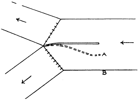
Fig. 27.
The Gagera branch of the Lower Chenab Canal—the left-hand branch in fig. 27—was found to silt. It was proposed to make a divide wall (fig. 27) extending up to full supply level. The idea is unintelligible. The silt does not travel by itself but is carried or rolled by the water. As long as water entered the Gagera branch, silt would go with it. The authorities, who had apparently accepted the proposal, altered the estimate when they received it, and ordered the wall to be made as shown dotted and of only half the height. This was done. The idea seems to have been that the wall would act as a sill[170] and stop rolling silt. This is intelligible, but such sills do not always have much effect on rolling silt. Moreover, there was a large gap, A B, in the wall. The work is said to have proved useless, and proposals have been made to continue the wall from A to B. In this form it is conceivable that it may be of use.
[171]
(See page 138.)
—Holes to be all dug out and thoroughly opened and inspected, then to be filled in with rammed earth. Never to be filled in a hurry or without digging out.
—Heavy soil to be dressed even. Light sandy soil to be disturbed as little as possible, and grass in such soil not to be removed except when in large tufts. When dressing is done, the road to be given (as far as possible) a transverse slope from the canal side of about 1 in 50.
—Branches to be lopped so as not to obstruct riders. Great care is needed to see that the men do not lop needlessly high. Roots, if projecting on road, to be covered up or cut out.
—Settlement or wearing down, if slight, should be made good on maintenance estimates, otherwise on special estimates. Cracks should be dug out and filled in and rammed. Old “dead men” or walls of earth should be utilised or at least levelled down.
—Can be dug out to a depth of 9 inches and removed to a distance, and (the places[172] having been inspected by the Subdivisional Officer) replaced by good soil got from pits or berms, the places being selected with care. If the lead is slightly askew, the stuff removed can be put in the same pits from which earth is got.
—This can be done in cases where the removal of sand or “reh” is not practicable or has proved ineffective. The grass is laid crosswise to prevent wheels sinking in.
—To be cut close to the ground or to be dug out by the roots when ordered. To be burned as soon as dry. Dead branches, twigs, etc., to be burned or removed to rest-houses, and not left about on canal land. Precautions to be taken against damage by fire to forests, etc. Clearance to include the channel[56] and both roads, and any jungle on the slopes of the spoil which obstructs the roads.[57]
[56] Jungle on inside slopes not to be cleared where banks fall in or where channel is too wide.
[57] When an embankment runs parallel to an inundation canal, a chain or so distant, the intervening space need not be cleared, nor need the top of a bank be cleared if it is so uneven that it is not a road.
—Trees which fall into a channel or across a road to have their branches cut away at once. The trunk to be removed so far as is possible. Trees which are dead or broken off should be felled, also those which have been blown into inclined positions, unless bad gaps will be caused. Trees (unless required for stock) to be sold as they lie and removed, including the parts below ground, by purchasers, within a fixed time. Logs, etc., not to be left lying about on canal land. Stumps, etc., to be made into charcoal and the holes filled up.
[173]
Note.—The above works (Parts I. and II.) to be done immediately after the rains (repairs to roads and removal of trees, branches, etc., being also done during the rains or whenever necessary) and finished at latest by 31st October.
—Gháts to be dressed, strengthened, and kept neat, the bank being thrown back and curved so as to give a long inner slope, and lumps, etc., levelled off.
—To be closed (by order of Subdivisional Officer and no one of lower rank) only when very near to a bridge or near to another ghát.[58] If closed, to be staked up and bushing to be added. Not to be closed by loose thorny branches. Not to be allowed close to any milestone, outlet, etc.
[58] Regarding gháts at bridges, see Chap. II., Art. 12.
—Gháts where only foot-passengers cross, can run diagonally up the slopes or as may be convenient. They should be dressed and kept in order.
—At all gháts care must be taken that the canal road, especially if used for driving, is not cut up and is kept in proper order.
—To be removed from the channel when it is laid dry, and not left till it is about to be reopened.[59] Old stakes, etc., to be sawn off when crooked or too high.
[59] Where the bed is too low, no rubbish clearance should be done except in the case of very large snags, etc.
—To be removed before water is expected (but not sooner than is necessary) and the banks repaired and made good.
[60] This applies to inundation canals.
[174]
(See page 138.)
—Masonry, plaster, pitching, etc., to be kept in repair. Pitching, where defective or out of line, to be made right. Bumping posts to be fixed in proper positions. Earth to be added to ramps, etc., where needed. Metalling to be regularly seen to. Needles, planks, hooks, railings, winches, lamp-posts, lamps, etc., to be kept in order and complete. Bricks, bats, etc., to be properly stacked. Needles, etc., to be neatly stacked on rests or with bricks under them. All surplus and useless needles, etc., to be removed. Huts to be kept in repair. Extra mud walls or screens not to be allowed when unsightly. All verandah openings to be edged with a 6-inch band of whitewash.
—All masonry to be kept free from jungle growth, and all piers free from caught jungle. For this purpose long bamboo weed-hooks to be supplied.
—Rubbish, lumps of earth, logs, etc., to be cleared away, pits and holes filled up. Banks, slopes, etc., of main and branch channels in the neighbourhood of the work to be specially levelled and dressed.
Note.—All works should be specially seen to in October, and everything be in order by 31st October.
[175]
(See page 138.)
[61] This is reprinted from Punjab Rivers and Works. It was drawn up for inundation canals and flood embankments.
—Every watchman employed to have a fixed headquarters and a fixed beat. If there is no permanent hut on or near the bank, grass huts should be erected by the men at the places fixed. The presence or absence of the men to be frequently tested by the mate and suboverseer. The suboverseers tests to be recorded in a book and to form the subject of frequent inquiry by the Subdivisional Officer, who will also record his remarks and take proper action in case the suboverseer is in fault.
—To be made to assist whenever possible. The allotment of a beat to each such man has been separately ordered.
—The men, when not otherwise occupied, to do petty repairs, etc., within their beats, but not to be put on miscellaneous duties and sent about as messengers, nor to act as orderlies or khalassies.
—Should generally[176] be greater for one and a half months in July and August than at other times. Care to be taken as to this and as to dismissing men when no longer needed.
—To be collected beforehand, if necessary, at suitable places, to be accounted for at end of flow season and balance taken care of.
—The Establishment to be trained by the Subdivisional Officer to report every breach to all officials with the greatest possible speed. The mate, daroga, and suboverseer to remain there till the breach is closed and to promptly send a report on the prescribed form to the Subdivisional Officer.
—In case of serious breaches of main channels the Subdivisional Officer to himself reach the spot as soon as possible.
—See printed form M[62] attached. To be promptly submitted for each breach to the Executive Engineer. The report contains a column for cost of closure. This means the stoppage of the flow and not the complete making up of the banks. The column for remarks of the Executive Engineer should be filled in and the report promptly returned to the Subdivisional Officer, who will, in the meantime, be making up the banks and preparing a requisition or estimate.
[62] Not printed.
—With the Executive Engineer’s monthly progress report a list of breaches will be submitted, canal by canal, with columns showing date of occurrence and cost of closure. The return should be on the attached form G.[63] The Subdivisional Officer should also submit this form to the Executive Engineer.
[63] Not printed. The form differs slightly from a form prescribed by the Chief Engineer for general use in the Province.
—The cost of breaches is not to be[177] charged to maintenance estimates. At the close of each month the Executive Engineer should submit or sanction an estimate, accompanied by the breach reports, for closing any breaches which have occurred and making up the banks.
—These may be of special importance. It may be impossible to do any good and money may be uselessly spent. In any such cases the Subdivisional Officer should at once proceed to the spot and the case should be reported by wire to the Executive Engineer and, if necessary, to the Superintending Engineer.
—The Subdivisional Officer must at once proceed to the spot and the case be reported by wire to the Executive Engineer and Superintending Engineer. The Breach Report forms can be submitted partially filled in at the earliest possible moment and a complete form afterwards.
[178]
(See page 139.)
1. The object of bushing is to form a silt berm and thus prevent or stop the falling in of the banks.
2. The branches must be thickly packed in order that the water among them may become still, and also in order that they may not be shifted by the stream. If thickly packed, the pegs required will also be fewer. Most of the branches should be leafy and freshly cut, but, mixed with these, there may be a proportion of kikar or other leafless branches. Frequently it is possible to utilise jungle trees of small value, bushes, scrub jungle, or even long grass.
3. Except when the bushes are to be very small or the length to be bushed very short, the proposed line for the edge of the berm should be marked out by long stakes driven in the water at fairly close intervals. Otherwise the work may be badly done and the berm formed imperfect and out of line.
4. As the berm formed is not likely in any case to be perfectly straight, and as subsequent additions to it will be difficult, while trimming it will be easy, the bushes should extend slightly beyond the line of the proposed berm. Care should be taken that the lower branches, which cannot be seen when once submerged, are long enough.
[179]
5. The branches should be piled up to above water-level, so that, as they settle, they will assume the position desired, but to lay them high above full-supply level on the slopes is useless and wasteful. If the pegs have to be driven at a high level, the branches should be attached to them by thin ropes or twine. Long pegs standing up high above the ground are also wasteful. The pegs should as far as possible be kept in line and their heads at one level.
6. If bushing is begun during low supply, it need not, at first, extend up to full-supply level. More branches, freshly cut, can be added as the supply rises. In any case it is generally necessary to make some additions to bushing from time to time, and this should be explained to contractors and others when fixing the rates.
7. If the trees from which branches are cut are in desirable places, the branches should be cut with judgment; but where trees are in places where they should not be (e.g., on the inside slopes of the channels), all the branches may be cut off. The trunk may be left temporarily in order to supply more branches.
[180]
(See page 9.)
There are no definite rules regarding the capacity of the escapes to be provided on a canal. On some canals in dry tracts of country the discharging power of the escapes is a mere fraction of that of the canal. In other cases it is about half that of the canal. In a district liable to heavy rain an escape, say at a point where a canal divides into branches, should be able to discharge about half of the main canal supply. On branches, escapes, if provided at all, usually discharge into reservoirs, and their period of working is very limited: it may be only twenty-four hours.
On distributaries, escapes are seldom provided. It has been suggested, in connection with modules, that the people irrigating from each watercourse should be responsible for disposing, by means of it, of a certain quantity of surplus water. This would be too rigid a rule. On some watercourses there is much waste land or land under rice cultivation; in such cases surplus water can be passed off without damage. The canal subordinates are fully cognisant of such cases, and they arrange accordingly. In other cases surplus water would do some damage; but on nearly every distributary the full supply, even when there is no demand for water, can be got rid of for a few hours, or even more, without a breach occurring.
[181]
Escapes at outlets, in connection with modules, can be arranged by means of waste weirs or by means of Gregotti’s syphons (sifoni autolivelatori). The following is an abridged translation of part of a pamphlet by Gregotti:—
The figure represents one of the syphons installed in the “Centrali Milani.”
A is the supply basin of the “Centrali,” which ends in the syphon B. The latter is constructed with mouthpiece of rectangular section a, which is submerged in the basin A. A weir divides the mouthpiece of the syphon from the descending branch, c, of the same, also rectangular in section. The weir crest is at level dd, from 2 to 7 cm. below the maximum level of water surface which it is desired not to exceed in the supply basin.
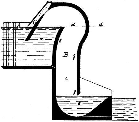
Fig. 28.
The descending branch, c, has at its base a small tank e, which forms a water seal. The syphon is completed by a tube f, which is attached to the intake branch of the syphon and which ends at a level of 2 to 7 cm. above the previously mentioned surface dd.
As soon as the water surface in the supply basin tends to rise above the plane dd, a filament of water, in falling over the weir b, pours down the descending branch c, and when the water has risen from 2 to 7 cm. above the crest of the weir, the thickness of the falling stream has become such that it is able, by lapping, with a wave-like course, the wall gg, to extract the air that has become enclosed in the syphon, and which cannot be replaced because the space in which the stream acts is closed at its base by the water in the tank e; and at the top also the aeration tube is closed by the rise in the water surface of the supply basin. From this point the syphon action quickly becomes fully established and begins to give its full discharge.
[182]
The discharge that is given is equal to that of an orifice in a thin partition if certain limitations are allowed for between the fall used in the syphon and the height of the arch, that is, the distance from the crest of the weir to the inside roof of the syphon.
The discharge is given by the formula
Q = μA√2gh.
Q = discharge of syphon in cubic metres per sec.
μ = a coefficient of reduction of discharge which varies between wide limits.
A = the minimum cross-sectional area of the syphon in square metres.
g = value of acceleration due to gravity.
h = the fall, or the difference of level in metres between the water surfaces in the supply basin A and in the small tank e.
As soon as the supply basin surface falls, the opening of the aeration tube becomes uncovered and air is drawn into the syphon. But until the surface has fallen some centimetres the supply of air is not sufficient to cause the syphon action to stop completely, and thus the escape varies gradually from the maximum discharge to zero as the water surface falls a few centimetres till it reaches its original level.
In certain cases it is possible to do without the aeration tube, especially when the fall used in the syphon is not great and when it is possible to arrange matters so that the velocity of the water flowing past in front of the syphon is small.
The syphon with a width of 3 metres escapes 8 cubic metres per sec. of water.
[183]
(See Chap. III., Arts. 2 and 3; also see Hydraulics, Chap. VIII., Art. 5, and Appendix H.)
1. The gauge should be placed on that bank and facing in that direction which enables it to be most conveniently read by the gauge reader and by officials passing the place.
2. The gauge should be of enamelled iron secured by copper screws to a post of squared and seasoned wood which is either driven beforehand[64] into the channel or spiked to a masonry work. Even in the deepest channel a long enough post can be arranged for. A masonry pillar is not necessary. The post may be rectangular in cross-section, with upstream and downstream edges cut sharp. This prevents, or greatly reduces, the heaping up of water at the upstream side and the formation of a hollow downstream. If the “Ward” gauge of two vertical planks is used, the planks should meet at an acute angle, not a right angle, and not be wider than 7 inches each.
[64] Driving after the gauge is attached may loosen or break the screws.
3. The top of the gauge should be slightly above the highest probable water-level. The post should extend up to the top of the gauge.
4. If ever the graded bed of the channel is altered the[184] zero of the gauge should be altered. There may be some risk of confusion at first, but it can be avoided by exercising due care and making notes. The levels of the old and new zeros should be recorded.
5. A gauge at a distance from the bank is objectionable. It collects jungle, cannot be properly read, and is liable to be damaged by floating logs or boats. A gauge should be as near as possible to one bank or the other. If the bank is vertical, the gauge should be quite close to it. If, owing to silt deposit, the gauge is dry at low supply, the deposit can be removed by the gauge reader.
6. Every regulator should be given a name, generally that of a neighbouring village and not that of a channel, and the gauge book headings should be drawn up in an intelligent and systematic manner. Each main channel should be entered in order, and each regulator on the channel—together with the head gauges of all channels which take off there—should be entered, commencing from upstream. A specimen is given on page 109. Thus the head gauge of any branch appears in the register of the main channel from which it takes off, other gauges on the branch appearing in the register for the branch. And similarly as regards a distributary which has gauges other than the head gauge.
7. Each gauge reader should be supplied with a register, each page having, besides the counterfoil, as many detachable slips—marked off by perforations—as there are officials—usually the Subdivisional Officer, zilladar and suboverseer—to whom daily gauge reports are to be sent. The titles and addresses of these officials are printed on the backs of the respective slips. The slips and counterfoil have printed on them a form—similar to part of the specimen shown on page 109—showing the names of all the gauges read by that particular gauge reader, so that he[185] has merely to fill in the date and readings, tear off the slips and despatch them. The posting of the register in the subdivision is facilitated if each gauge has a number and if the corresponding numbers are printed—besides the names—on the gauge slips. If the gauge reader does not know English, the headings of the slips are printed in the vernacular. If the gauge readings are telegraphed, there may be only one slip—besides the counterfoil—which is sent to the telegraph signaller.
[186]
(See p. 164.)
[65] This description has been supplied by Glenfield & Kennedy, Kilmarnock. The modules can, it is understood, be obtained from them.
The attributes of a perfect module are many and varied, but in Gibb’s module they have all been successfully embodied in what is probably the simplest piece of apparatus of its kind ever devised. The following summary of the characteristics of Gibb’s module is, therefore, equivalent to an enumeration of the attributes of a perfect module:—
Gibb’s module
| Cannot be tampered with, | - | since it has no moving parts, and because of its extreme simplicity. | |
| Cannot get out of order, | |||
| Silt or other solid matter in the water cannot affect its action, | |||
| Requires no attention, |
| It is accurate, | - | being designed on scientific hydraulic principles. | |
| Works with very small loss of head, |
It is portable, and can be erected at any desired site very simply and easily.
It is strong and durable.
[187]
The range of variation of both up- and downstream water-levels through which the discharge remains constant is more than sufficient to meet all the requirements of irrigation canals.
The sufficiency of the delivery can be ascertained at a glance.
The water can be drawn from any desired depth in the parent channel.
When desired, means are provided whereby the supply can be closed or opened at will.
Means are provided, if desired, for a sudden increase of discharge when the upstream water-level exceeds a certain limit, so that surplus water, which might endanger the safety of the canal, is allowed to escape into the branch whenever the danger limit is reached. The upstream water-level at which escapement begins can be fixed in accordance with the requirements of each site, and the action of the escape notch is independent of the opening and closing of the module.
No designing or calculations are required. These have already been worked out. Known the discharge required, the module is supplied complete and ready for setting in position in the canal bank.
The entire absence of moving parts is the chief feature of Gibb’s module; the water simply regulates itself by using up all the excess of energy over and above that required to discharge the correct supply of water. The way in which this takes place will be understood from the following analogy:—
[188]
We all know that when we stir tea in a cup so as to make it spin, the liquid rises at the rim of the cup and curves down into a depression in the middle, and the greater the spin the more marked this effect is. It is, we know, the centrifugal force produced by the spin that makes the tea remain high at the rim of the cup. If, while the tea is thus spinning, a teaspoon is held so that it dips slightly below the surface of the liquid near the rim, it will obstruct the flow of the outer portion of the liquid, which will fall in towards the depression in the middle. The reason for this, of course, is that the centrifugal force is absorbed when we interrupt any part of the spin with the teaspoon; hence the liquid must fall, and we know that when liquid falls it uses up “head” or energy.
In Gibb’s module a similar action is made to take place in a steel chamber, semicircular or spiral in plan, through which the water flows in a semicircular path instead of circulating round and round as in the teacup. The surface of the stream, however, assumes the same form as it does in a cup, because it flows under the same conditions. Across the chamber are fixed a number of vertical steel diaphragm plates which take the place of the teaspoon in the above analogy. The lower edges of these plates are of such a shape, and they are fixed at such a height from the bottom of the chamber, as to allow a stream of just the correct required discharge of water to flow under them without interference. But if, owing to an increase of head caused by a rise in the upstream water-level, the water tends to rise higher at the circumference of the chamber, then the water at the surface of the stream strikes against the diaphragm plates, and its centrifugal force being absorbed, it will fall in towards the centre just as[189] happened in the teacup when the spoon was used in place of these plates. In this way the excess head that caused the additional rise of water at the circumference is used up by the fall back towards the centre. The full capacity of the semicircle or spiral for using up excess head or energy in this way is made available by the use of a sufficient number of diaphragm plates fixed at suitable intervals. When the range of head to be dealt with is not large, then a semicircular chamber is sufficient; but for large ranges of head the chamber is made of spiral form so as to lead the water round a complete revolution or more, as may be necessary.
Fig. 29 shows the general form and structure of the type of module suitable for irrigation. Fig. 30 is from a photograph.
The working chamber or shell A is constructed of mild steel plating securely riveted to a framework of angle steel, and the semicircular form of the shell with the rigid diaphragm plates B B riveted to the walls makes a very strong structure, and ensures durability.
The “leading-in” bend C is of cast iron strongly bolted to the steel shell, and is so designed as to deliver the water into the module chamber in a completely established vortex condition.
The socket D on this “leading-in” bend is made so as to allow of considerable latitude in the vertical alignment of the straight leading-in pipe, so that the water can be drawn from any desired depth in the parent channel, and the proportion of silt drawn off is thus brought under control.
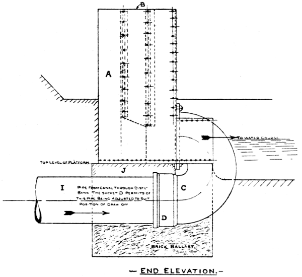
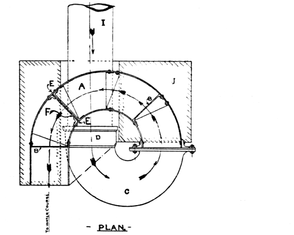

Fig. 29.—Details of Gibb’s Patent Module.
Large illustrations: End Elevation (top) (153 kB)
Plan (middle) (114 kB)
Front Elevation (bottom) (229 kB)
Grooves E E and a shutter F, as illustrated, for closing[190]
[191]
off the flow through the module, are provided, if required,
but all modules are not fitted in this way, because many
irrigation authorities consider it undesirable to provide
the consumers with unrestricted facilities for closing
off their supplies without previously giving notice of
such an action.

Fig. 30.—The Completed Module (Open Type for Low Heads).
An escape notch H is provided in the position indicated when desired. It may, however, be found difficult to determine beforehand the upstream water-level at[192] which it is necessary to allow this escape of surplus supply, so that it is generally more satisfactory to cut the escape notch after the modules have been installed and actual experience has indicated a suitable level for the notch crest.
In the standard type of module for irrigation purposes the top of the module chamber is completely open, as shown, and this is the type generally recommended, as it is found that consumers have greater confidence in an apparatus which hides nothing from them. To meet the needs of special cases, however, a second type is also made in which the chamber is completely closed and considerably reduced in height, being thus specially suitable for sites where space is confined.
Pipes I, of diameter suitable for all sizes of modules, are also supplied. These may either be welded steel or cast iron, as desired. An 18-feet length of pipe is usually found sufficient to bring the supply through the canal bank to the module.
All modules supplied are treated with anti-corrosive paint, which ensures the protection of the metal.
[193]
(See p. 168.)
[66] See Punjab Irrigation Branch Paper No. 12, “Results of Tests of Kennedy’s Gauge Outlet.”
Fig. 31 shows a bell-mouthed orifice discharging into an air-space. The jet springs across the air-space and traverses a gradually diverging tube. Let a, A be the sectional areas of the stream at the air-space and the downstream end of the tube respectively, and let V, v, and Pₐ, P₁ be the corresponding velocities and pressures. Let resistances be neglected. Since the pressure in the air-space is Pₐ,
V = √2gh₀
or the discharge through the tube depends only on h₀ and not on h₁.
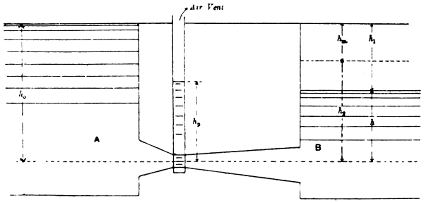
Fig. 31.
[194]
By Bernouilli’s theorem,
V²2g + PₐW = v²2g + P₁W
or
P₁ - PₐW = V² - v²2g.
This quantity (since v is small) is not much less than h₀ or V²2g. In other words, the water levels of two cisterns with an air-space between them differ only a little, or h₁ is small.
The above case (two cisterns and air-space) is mentioned in Hydraulics, Chap. V. The principle is simply that the velocity head at the air-space is reconverted into pressure head by passing the stream through a gradually diverging tube. In the absence of such a tube the velocity head would be wasted by causing eddies in the downstream cistern.
If the downstream cistern is a watercourse whose water-level is considerably lower than that of the upstream cistern or distributary, V is obviously unaffected. Also P₁ is obviously reduced. Therefore, by Bernouilli, v is increased, or the stream does not fill the expanded tube and there are eddies in the tube. The water-level in the watercourse may even be lower than the end of the tube. The discharge is unaffected.
In practice there are, of course, resistances, but this fact does not affect the general conclusions stated above. The minimum working head (difference between the two water-levels) which gives a constant discharge is greater than would be the case in the absence of resistances. This “minimum working head for modularity” has been found to be ·21 foot, ·42 foot, and ·61 foot, the corresponding values of the “depression,” h₀, being respectively[195] 1 foot, 2 feet, and 3 feet. When the working head is less than the above, the discharge is less and it depends on the working head. The depression should, according to Kennedy, be about 1·75 feet, but it may be more.
The chief difficulty in using the gauge outlet as a module is that the air vent can be stopped up. This converts the apparatus into a compound diverging tube (Hydraulics, Chap. III., Art. 17). The discharge is, of course, increased, and it becomes dependent at all times on the working head. Another difficulty is that any rise or fall in the water-level of the distributary (and such rises and falls may occur owing to silting or scour, however carefully the discharge may be regulated) alters the discharge somewhat, though not to the same degree as in an ordinary outlet with a working head of, say, ·5 foot. In short, Kennedy’s gauge outlet, or “semi-module” as it is sometimes called, can modify but not do away with the variations of the discharges of outlets.
[196]
Harvey & Healing, Printers, Manchester Street, Cheltenham.
The inconsistent use of periods after Roman numerals has been retained; other inconsistencies (spelling, hyphenation, formatting and lay-out) have been retained as well, except when mentioned below.
Depending on the hard- and software used and their settings, not all elements may display as intended. Some of the tables are best viewed in a wide window.
Page 21: The equation does not agree with the calculations given.
Page 66, Fig. 11: There are two illustrations labelled Fig. 11, the hyperlinks point to the appropriate illustration.
Changes made
Obvious typographical errors have been corrected silently. Footnotes and illustrations have been moved out of text paragraphs. Some tables have been re-arranged or split; in several tables, the data alignment has been standardised.
Page 18, table, Total of second column: 8·93 changed to 8·01
Page 39: Kutters changed to Kutter’s
Page 93: marked out changed to marked at
Page 69: 3 Depth of digging changed to 13. Depth of digging
Page 109, first average ·1 changed to 4·1
Page 117: Net Areas Irrigated in Areas changed to Net Areas Irrigated in Acres
Page 150: Cusecs. added as in similar tables
Index: Cattle Ghats changed to Cattle Gháts; Line for making ... changed to Lime for making ...; Lower Chenal Canal changed to Lower Chenab Canal.
End of the Project Gutenberg EBook of Irrigation Works, by E. S. Bellasis

*** END OF THIS PROJECT GUTENBERG EBOOK IRRIGATION WORKS ***

***** This file should be named 56113-h.htm or 56113-h.zip *****
This and all associated files of various formats will be found in:
        http://www.gutenberg.org/5/6/1/1/56113/

Produced by Chris Curnow, Harry Lame
and the Online Distributed Proofreading Team at
http://www.pgdp.net (This file was produced from images
generously made available by The Internet Archive)


Updated editions will replace the previous one--the old editions will
be renamed.

Creating the works from print editions not protected by U.S. copyright
law means that no one owns a United States copyright in these works,
so the Foundation (and you!) can copy and distribute it in the United
States without permission and without paying copyright
royalties. Special rules, set forth in the General Terms of Use part
of this license, apply to copying and distributing Project
Gutenberg-tm electronic works to protect the PROJECT GUTENBERG-tm
concept and trademark. Project Gutenberg is a registered trademark,
and may not be used if you charge for the eBooks, unless you receive
specific permission. If you do not charge anything for copies of this
eBook, complying with the rules is very easy. You may use this eBook
for nearly any purpose such as creation of derivative works, reports,
performances and research. They may be modified and printed and given
away--you may do practically ANYTHING in the United States with eBooks
not protected by U.S. copyright law. Redistribution is subject to the
trademark license, especially commercial redistribution.

START: FULL LICENSE

THE FULL PROJECT GUTENBERG LICENSE
PLEASE READ THIS BEFORE YOU DISTRIBUTE OR USE THIS WORK

To protect the Project Gutenberg-tm mission of promoting the free
distribution of electronic works, by using or distributing this work
(or any other work associated in any way with the phrase "Project
Gutenberg"), you agree to comply with all the terms of the Full
Project Gutenberg-tm License available with this file or online at
www.gutenberg.org/license.

Section 1. General Terms of Use and Redistributing Project
Gutenberg-tm electronic works

1.A. By reading or using any part of this Project Gutenberg-tm
electronic work, you indicate that you have read, understand, agree to
and accept all the terms of this license and intellectual property
(trademark/copyright) agreement. If you do not agree to abide by all
the terms of this agreement, you must cease using and return or
destroy all copies of Project Gutenberg-tm electronic works in your
possession. If you paid a fee for obtaining a copy of or access to a
Project Gutenberg-tm electronic work and you do not agree to be bound
by the terms of this agreement, you may obtain a refund from the
person or entity to whom you paid the fee as set forth in paragraph
1.E.8.

1.B. "Project Gutenberg" is a registered trademark. It may only be
used on or associated in any way with an electronic work by people who
agree to be bound by the terms of this agreement. There are a few
things that you can do with most Project Gutenberg-tm electronic works
even without complying with the full terms of this agreement. See
paragraph 1.C below. There are a lot of things you can do with Project
Gutenberg-tm electronic works if you follow the terms of this
agreement and help preserve free future access to Project Gutenberg-tm
electronic works. See paragraph 1.E below.

1.C. The Project Gutenberg Literary Archive Foundation ("the
Foundation" or PGLAF), owns a compilation copyright in the collection
of Project Gutenberg-tm electronic works. Nearly all the individual
works in the collection are in the public domain in the United
States. If an individual work is unprotected by copyright law in the
United States and you are located in the United States, we do not
claim a right to prevent you from copying, distributing, performing,
displaying or creating derivative works based on the work as long as
all references to Project Gutenberg are removed. Of course, we hope
that you will support the Project Gutenberg-tm mission of promoting
free access to electronic works by freely sharing Project Gutenberg-tm
works in compliance with the terms of this agreement for keeping the
Project Gutenberg-tm name associated with the work. You can easily
comply with the terms of this agreement by keeping this work in the
same format with its attached full Project Gutenberg-tm License when
you share it without charge with others.

1.D. The copyright laws of the place where you are located also govern
what you can do with this work. Copyright laws in most countries are
in a constant state of change. If you are outside the United States,
check the laws of your country in addition to the terms of this
agreement before downloading, copying, displaying, performing,
distributing or creating derivative works based on this work or any
other Project Gutenberg-tm work. The Foundation makes no
representations concerning the copyright status of any work in any
country outside the United States.

1.E. Unless you have removed all references to Project Gutenberg:

1.E.1. The following sentence, with active links to, or other
immediate access to, the full Project Gutenberg-tm License must appear
prominently whenever any copy of a Project Gutenberg-tm work (any work
on which the phrase "Project Gutenberg" appears, or with which the
phrase "Project Gutenberg" is associated) is accessed, displayed,
performed, viewed, copied or distributed:

  This eBook is for the use of anyone anywhere in the United States and
  most other parts of the world at no cost and with almost no
  restrictions whatsoever. You may copy it, give it away or re-use it
  under the terms of the Project Gutenberg License included with this
  eBook or online at www.gutenberg.org. If you are not located in the
  United States, you'll have to check the laws of the country where you
  are located before using this ebook.

1.E.2. If an individual Project Gutenberg-tm electronic work is
derived from texts not protected by U.S. copyright law (does not
contain a notice indicating that it is posted with permission of the
copyright holder), the work can be copied and distributed to anyone in
the United States without paying any fees or charges. If you are
redistributing or providing access to a work with the phrase "Project
Gutenberg" associated with or appearing on the work, you must comply
either with the requirements of paragraphs 1.E.1 through 1.E.7 or
obtain permission for the use of the work and the Project Gutenberg-tm
trademark as set forth in paragraphs 1.E.8 or 1.E.9.

1.E.3. If an individual Project Gutenberg-tm electronic work is posted
with the permission of the copyright holder, your use and distribution
must comply with both paragraphs 1.E.1 through 1.E.7 and any
additional terms imposed by the copyright holder. Additional terms
will be linked to the Project Gutenberg-tm License for all works
posted with the permission of the copyright holder found at the
beginning of this work.

1.E.4. Do not unlink or detach or remove the full Project Gutenberg-tm
License terms from this work, or any files containing a part of this
work or any other work associated with Project Gutenberg-tm.

1.E.5. Do not copy, display, perform, distribute or redistribute this
electronic work, or any part of this electronic work, without
prominently displaying the sentence set forth in paragraph 1.E.1 with
active links or immediate access to the full terms of the Project
Gutenberg-tm License.

1.E.6. You may convert to and distribute this work in any binary,
compressed, marked up, nonproprietary or proprietary form, including
any word processing or hypertext form. However, if you provide access
to or distribute copies of a Project Gutenberg-tm work in a format
other than "Plain Vanilla ASCII" or other format used in the official
version posted on the official Project Gutenberg-tm web site
(www.gutenberg.org), you must, at no additional cost, fee or expense
to the user, provide a copy, a means of exporting a copy, or a means
of obtaining a copy upon request, of the work in its original "Plain
Vanilla ASCII" or other form. Any alternate format must include the
full Project Gutenberg-tm License as specified in paragraph 1.E.1.

1.E.7. Do not charge a fee for access to, viewing, displaying,
performing, copying or distributing any Project Gutenberg-tm works
unless you comply with paragraph 1.E.8 or 1.E.9.

1.E.8. You may charge a reasonable fee for copies of or providing
access to or distributing Project Gutenberg-tm electronic works
provided that

* You pay a royalty fee of 20% of the gross profits you derive from
  the use of Project Gutenberg-tm works calculated using the method
  you already use to calculate your applicable taxes. The fee is owed
  to the owner of the Project Gutenberg-tm trademark, but he has
  agreed to donate royalties under this paragraph to the Project
  Gutenberg Literary Archive Foundation. Royalty payments must be paid
  within 60 days following each date on which you prepare (or are
  legally required to prepare) your periodic tax returns. Royalty
  payments should be clearly marked as such and sent to the Project
  Gutenberg Literary Archive Foundation at the address specified in
  Section 4, "Information about donations to the Project Gutenberg
  Literary Archive Foundation."

* You provide a full refund of any money paid by a user who notifies
  you in writing (or by e-mail) within 30 days of receipt that s/he
  does not agree to the terms of the full Project Gutenberg-tm
  License. You must require such a user to return or destroy all
  copies of the works possessed in a physical medium and discontinue
  all use of and all access to other copies of Project Gutenberg-tm
  works.

* You provide, in accordance with paragraph 1.F.3, a full refund of
  any money paid for a work or a replacement copy, if a defect in the
  electronic work is discovered and reported to you within 90 days of
  receipt of the work.

* You comply with all other terms of this agreement for free
  distribution of Project Gutenberg-tm works.

1.E.9. If you wish to charge a fee or distribute a Project
Gutenberg-tm electronic work or group of works on different terms than
are set forth in this agreement, you must obtain permission in writing
from both the Project Gutenberg Literary Archive Foundation and The
Project Gutenberg Trademark LLC, the owner of the Project Gutenberg-tm
trademark. Contact the Foundation as set forth in Section 3 below.

1.F.

1.F.1. Project Gutenberg volunteers and employees expend considerable
effort to identify, do copyright research on, transcribe and proofread
works not protected by U.S. copyright law in creating the Project
Gutenberg-tm collection. Despite these efforts, Project Gutenberg-tm
electronic works, and the medium on which they may be stored, may
contain "Defects," such as, but not limited to, incomplete, inaccurate
or corrupt data, transcription errors, a copyright or other
intellectual property infringement, a defective or damaged disk or
other medium, a computer virus, or computer codes that damage or
cannot be read by your equipment.

1.F.2. LIMITED WARRANTY, DISCLAIMER OF DAMAGES - Except for the "Right
of Replacement or Refund" described in paragraph 1.F.3, the Project
Gutenberg Literary Archive Foundation, the owner of the Project
Gutenberg-tm trademark, and any other party distributing a Project
Gutenberg-tm electronic work under this agreement, disclaim all
liability to you for damages, costs and expenses, including legal
fees. YOU AGREE THAT YOU HAVE NO REMEDIES FOR NEGLIGENCE, STRICT
LIABILITY, BREACH OF WARRANTY OR BREACH OF CONTRACT EXCEPT THOSE
PROVIDED IN PARAGRAPH 1.F.3. YOU AGREE THAT THE FOUNDATION, THE
TRADEMARK OWNER, AND ANY DISTRIBUTOR UNDER THIS AGREEMENT WILL NOT BE
LIABLE TO YOU FOR ACTUAL, DIRECT, INDIRECT, CONSEQUENTIAL, PUNITIVE OR
INCIDENTAL DAMAGES EVEN IF YOU GIVE NOTICE OF THE POSSIBILITY OF SUCH
DAMAGE.

1.F.3. LIMITED RIGHT OF REPLACEMENT OR REFUND - If you discover a
defect in this electronic work within 90 days of receiving it, you can
receive a refund of the money (if any) you paid for it by sending a
written explanation to the person you received the work from. If you
received the work on a physical medium, you must return the medium
with your written explanation. The person or entity that provided you
with the defective work may elect to provide a replacement copy in
lieu of a refund. If you received the work electronically, the person
or entity providing it to you may choose to give you a second
opportunity to receive the work electronically in lieu of a refund. If
the second copy is also defective, you may demand a refund in writing
without further opportunities to fix the problem.

1.F.4. Except for the limited right of replacement or refund set forth
in paragraph 1.F.3, this work is provided to you 'AS-IS', WITH NO
OTHER WARRANTIES OF ANY KIND, EXPRESS OR IMPLIED, INCLUDING BUT NOT
LIMITED TO WARRANTIES OF MERCHANTABILITY OR FITNESS FOR ANY PURPOSE.

1.F.5. Some states do not allow disclaimers of certain implied
warranties or the exclusion or limitation of certain types of
damages. If any disclaimer or limitation set forth in this agreement
violates the law of the state applicable to this agreement, the
agreement shall be interpreted to make the maximum disclaimer or
limitation permitted by the applicable state law. The invalidity or
unenforceability of any provision of this agreement shall not void the
remaining provisions.

1.F.6. INDEMNITY - You agree to indemnify and hold the Foundation, the
trademark owner, any agent or employee of the Foundation, anyone
providing copies of Project Gutenberg-tm electronic works in
accordance with this agreement, and any volunteers associated with the
production, promotion and distribution of Project Gutenberg-tm
electronic works, harmless from all liability, costs and expenses,
including legal fees, that arise directly or indirectly from any of
the following which you do or cause to occur: (a) distribution of this
or any Project Gutenberg-tm work, (b) alteration, modification, or
additions or deletions to any Project Gutenberg-tm work, and (c) any
Defect you cause.

Section 2. Information about the Mission of Project Gutenberg-tm

Project Gutenberg-tm is synonymous with the free distribution of
electronic works in formats readable by the widest variety of
computers including obsolete, old, middle-aged and new computers. It
exists because of the efforts of hundreds of volunteers and donations
from people in all walks of life.

Volunteers and financial support to provide volunteers with the
assistance they need are critical to reaching Project Gutenberg-tm's
goals and ensuring that the Project Gutenberg-tm collection will
remain freely available for generations to come. In 2001, the Project
Gutenberg Literary Archive Foundation was created to provide a secure
and permanent future for Project Gutenberg-tm and future
generations. To learn more about the Project Gutenberg Literary
Archive Foundation and how your efforts and donations can help, see
Sections 3 and 4 and the Foundation information page at
www.gutenberg.org Section 3. Information about the Project Gutenberg
Literary Archive Foundation

The Project Gutenberg Literary Archive Foundation is a non profit
501(c)(3) educational corporation organized under the laws of the
state of Mississippi and granted tax exempt status by the Internal
Revenue Service. The Foundation's EIN or federal tax identification
number is 64-6221541. Contributions to the Project Gutenberg Literary
Archive Foundation are tax deductible to the full extent permitted by
U.S. federal laws and your state's laws.

The Foundation's principal office is in Fairbanks, Alaska, with the
mailing address: PO Box 750175, Fairbanks, AK 99775, but its
volunteers and employees are scattered throughout numerous
locations. Its business office is located at 809 North 1500 West, Salt
Lake City, UT 84116, (801) 596-1887. Email contact links and up to
date contact information can be found at the Foundation's web site and
official page at www.gutenberg.org/contact

For additional contact information:

    Dr. Gregory B. Newby
    Chief Executive and Director
    gbnewby@pglaf.org

Section 4. Information about Donations to the Project Gutenberg
Literary Archive Foundation

Project Gutenberg-tm depends upon and cannot survive without wide
spread public support and donations to carry out its mission of
increasing the number of public domain and licensed works that can be
freely distributed in machine readable form accessible by the widest
array of equipment including outdated equipment. Many small donations
($1 to $5,000) are particularly important to maintaining tax exempt
status with the IRS.

The Foundation is committed to complying with the laws regulating
charities and charitable donations in all 50 states of the United
States. Compliance requirements are not uniform and it takes a
considerable effort, much paperwork and many fees to meet and keep up
with these requirements. We do not solicit donations in locations
where we have not received written confirmation of compliance. To SEND
DONATIONS or determine the status of compliance for any particular
state visit www.gutenberg.org/donate

While we cannot and do not solicit contributions from states where we
have not met the solicitation requirements, we know of no prohibition
against accepting unsolicited donations from donors in such states who
approach us with offers to donate.

International donations are gratefully accepted, but we cannot make
any statements concerning tax treatment of donations received from
outside the United States. U.S. laws alone swamp our small staff.

Please check the Project Gutenberg Web pages for current donation
methods and addresses. Donations are accepted in a number of other
ways including checks, online payments and credit card donations. To
donate, please visit: www.gutenberg.org/donate

Section 5. General Information About Project Gutenberg-tm electronic works.

Professor Michael S. Hart was the originator of the Project
Gutenberg-tm concept of a library of electronic works that could be
freely shared with anyone. For forty years, he produced and
distributed Project Gutenberg-tm eBooks with only a loose network of
volunteer support.

Project Gutenberg-tm eBooks are often created from several printed
editions, all of which are confirmed as not protected by copyright in
the U.S. unless a copyright notice is included. Thus, we do not
necessarily keep eBooks in compliance with any particular paper
edition.

Most people start at our Web site which has the main PG search
facility: www.gutenberg.org

This Web site includes information about Project Gutenberg-tm,
including how to make donations to the Project Gutenberg Literary
Archive Foundation, how to help produce our new eBooks, and how to
subscribe to our email newsletter to hear about new eBooks.
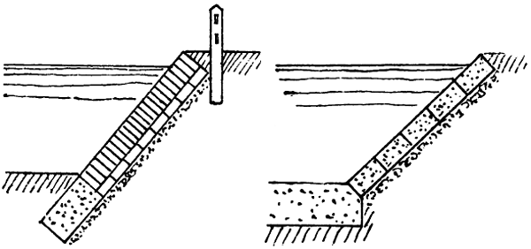
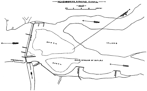

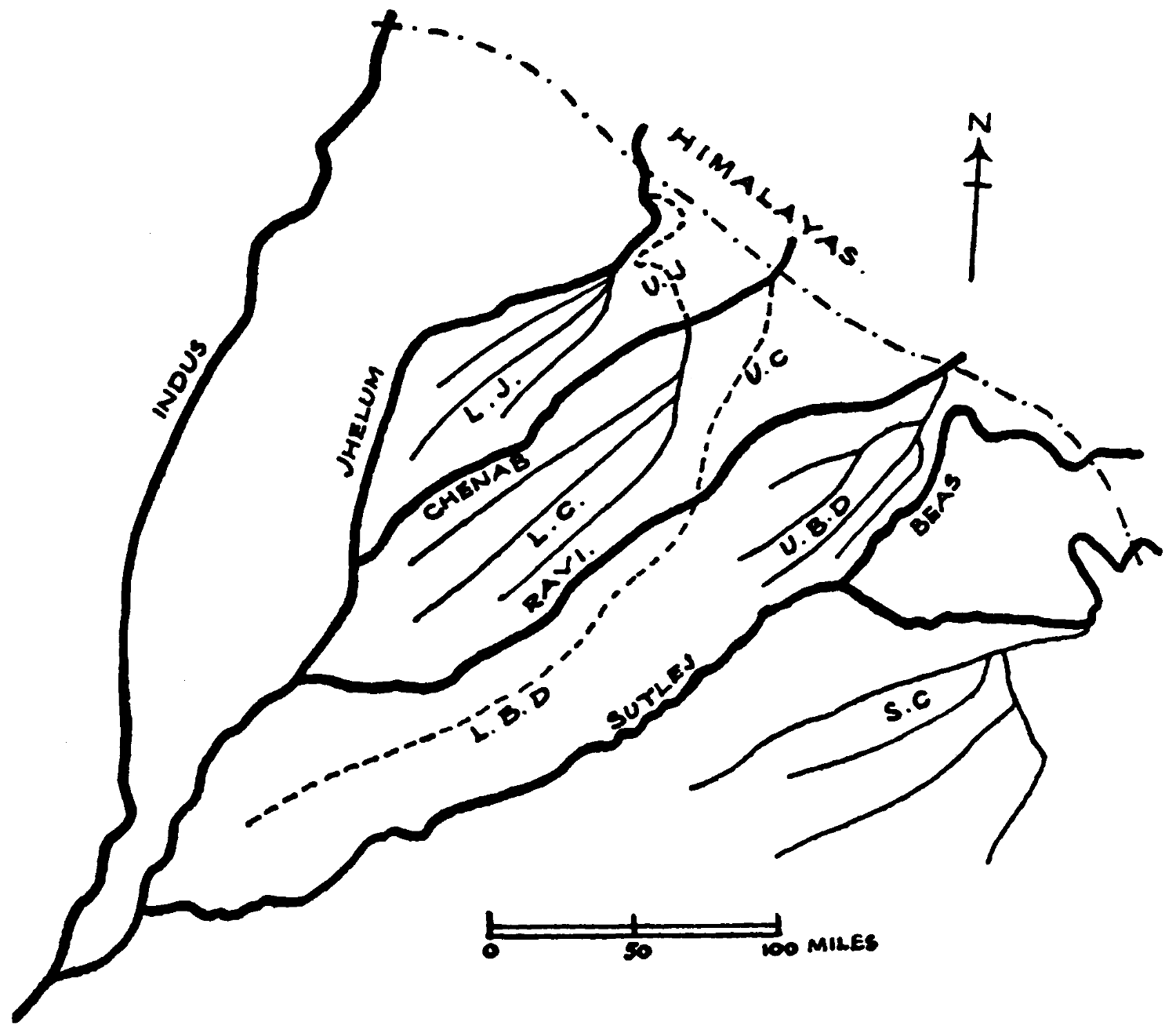
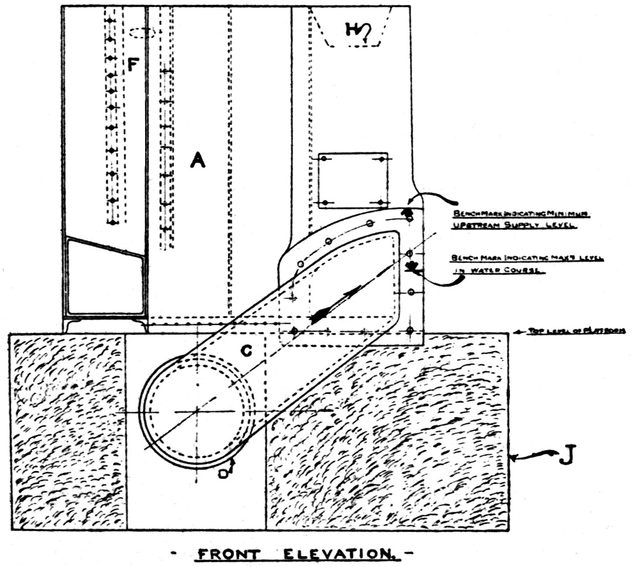