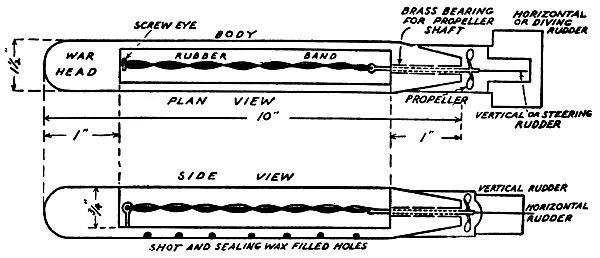
Transcriber's Note: If supported by your device, larger versions of many of the photographs and diagrams may be seen by clicking on the image.


Submarine! It’s a word that’s in everybody’s mind—on every one’s tongue.
The very sound of it conjures up thoughts of great ships that were and will be torpedoed and sent to the bottom of the old ocean to rust and to rot there.
Of all the mighty monsters that ever sailed the seven seas this piratical craft is by long odds the most daring as well as the most dangerous to both life and property.
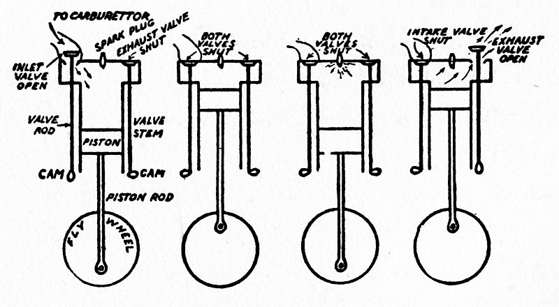
And yet while of course you know that a submarine can travel on or under the water, dive like a porpoise and destroy an enemy ship by shooting a torpedo at her, do you know exactly how an undersea boat works and fights and just how she does all the seemingly impossible feats for which she is notorious?
At the present time the greatest war in the world’s history is being fought, and you are more than a mere looker-on for your country is in it and you may be one of the boys who will be called to the colors to defend her on, or against, these undersea craft.
If for no other reason than this you ought to follow not only the battles as they are being fought on the east and west fronts of Europe, but the warfare that is being waged by the submarines on the high[viii] seas, for on these boats hinges to a very large extent the outcome of the war.
Ever since the year of 1900 when five of the first really successful submarines were built in the United States and sent to England the value of this kind of war-craft has gone forward by leaps and bounds as the devices for operating them were more and more improved.
Further too the submarine has played a far larger part in the war that is now going on than the wildest fancies of her inventors of twenty years ago could have pictured, much less believed, and what is of even greater import she bids fair to become the champion fighter of the sea in the future.
Indeed so wonderful is the submarine and so great are her possibilities that you should by all means know exactly how she is made and works, as well as her torpedoes. The easiest and certainly the most interesting way to find out these things is to read this book and then build a model submarine and torpedo according to the simple directions we have given.
To open the covers of this book and to read it is the next thing to going through the hatch in the bridge of the conning tower and examining the mechanism at first hand. So do it now.
| PAGE | ||
| “A Word to You” | vii | |
| CHAPTER | ||
| I. | The First of the Submarines | 1 |
How the Submarine Came to Be.—The Development of
the Submarine.—The First Submarine Boat.—A Submarine
of the Revolution.—The First Torpedo Fired by a Submarine.—Robert
Fulton’s Submarine.—The Earliest Steam
Propelled Submarine.—The Coming of the Torpedo-Tube
Submarine.—The Invention of the Electric Submarine.—What
the Gas Engine Did for the Submarine.—The Two
Types of Submarines. |
||
| II. | How to Make and Work a Model Submarine | 23 |
The Ballast Tank.—The Air Control Mechanism.—About
the Power Plant.—The Pusher Control Device.—The Propeller-Shaft.—Installing
the Motor.—Ballasting the Boat.—Making
the Superstructure.—And Now the Conning Tower.—Setting
the Propeller.—Putting on the Rudder.—Painting
Your Craft.—How to Work Your Submarine. |
||
| III. | How a Real Submarine Is Made and Works | 51 |
The Parts of a Submarine.—How the Hull Is Made.—What
the Superstructure Is.—The Outside of the Conning
Tower.—A Look Inside of the Hull.—A Peep into the
Conning Tower.—Now the Navigating Compartment.—Next,
the Diving Control Compartment.—The Four States
of the Submarine.—How a Submarine Dives.—The Ballast
Pumps and What They Do.—What the Buoyancy Tanks
Are For.—Compressed Air and Air-Compressor Pumps.—Inside
the Torpedo Compartment.—Why Trimming Tanks
Are Used.—In the Mine Compartment.—And Last of All,
the Sea Anchor.—Where the Crew of a Submarine Lives. |
||
| IV. | The Heart of the Submarine | 73 |
What a Good Power Plant Is.—The Faults of the Steam
Engine.—When the Gasoline Engine Came.—How the
Gasoline Engine Works.—The Last Word in Submarine
Engines.—Why an Electric Power Plant Is Needed.—The
Dynamo-Motor and Storage Battery System. |
||
| V. | Making and Shooting the Torpedo | 91 |
The First Submarine Torpedoes.—How to Make a Model
Submarine Torpedo.—The Body of the Torpedo.—Your
Torpedo in Action.—How a Real Torpedo Is Made.—The
Detonating, or Firing Mechanism.—The Engine that Drives
the Torpedo.—How a Torpedo Is Shot at a Ship.—A Torpedo
with a Cannon in It. |
||
| [x]VI. | Making the Submarine Deadlier | 115 |
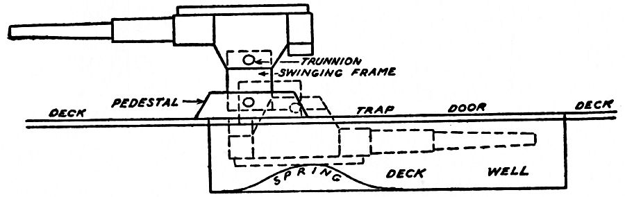
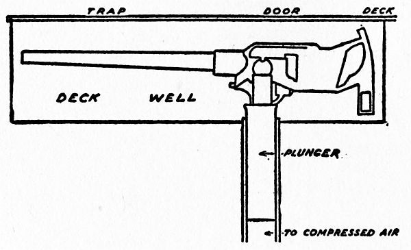
Arming the Submarine with Guns.—The Need of a Quick-Action
Gun.—The Spring Action Gun.—The Compressed
Air Action Gun.—How a Submarine Lays Mines.—Kinds
of Submarine Mines.—How the Mines Are Made. |
||
| VII. | The Wonderful Eye of the Submarine | 129 |
How the Eye of the Submarine Got Its Name.—The First
Submarine Eye, or Periscope.—How to Make a Simple
Periscope.—The Modern Lenticular Periscope.—How the
Telescope Is Made.—The Latest Type of Periscope.—The
Limited Use of the Periscope.—The New Enemy of the
Submarine. |
||
| VIII. | The Marvelous Tongue and Ears of the Submarine | 143 |
The Tongue and Ears of a Submarine.—Kinds of Signaling
Systems.—The Wigwag Way of Signaling.—The Flashlight
System.—The Wireless Telegraph System.—Underwater
Signaling Systems.—The Electric Current, or Conductivity
System. |
||
| IX. | The Crew of the Submarine | 159 |
Conditions on Early Submarine Craft.—When Crews Were
Hard to Sign.—What the Base-Ship Is For.—How Men
Are Trained for Submarine Duty.—The Complement of
a Submarine.—Breaking in Raw Recruits.—The Conditions
in War Time. |
||
| X. | How the Submarine Attacks | 171 |
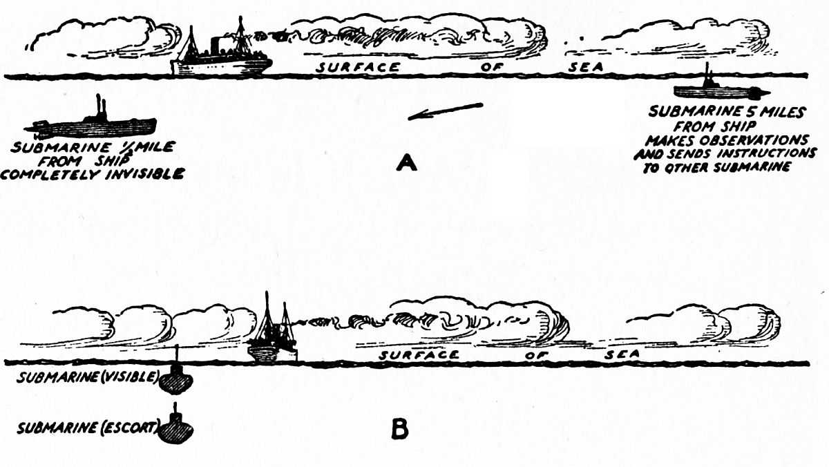
The Uses of the Submarine.—The Submarine as a Scout.—The
Submarine as a Blockader.—How a Submarine Attacks
a Merchantman.—When Submarines Attack in Pairs. |
||
| XI. | The New Submarine Chasers | 185 |
Schemes for Outwitting the Submarine.—Plans for Destroying
the U-Boats.—Kinds of Submarine Chasers.—How
the Chaser Chases a Submarine.—Shooting the Guns
of the Chaser.—Submarine Air Chasers.—A Way to Lift
the U-Boat Blockade. |
||
| XII. | The Last Word in Submarines | 199 |
Uncle Sam’s Latest Submarines.—The Great Blockades of
the Warring Nations.—The First of the Merchant Submarines.—Some
Facts About the Deutschland.—How the
United States Can Break the Blockade.—When Submarine |
||
A Modern American Submarine Cruising in the Afloat Condition with Foreward Diving-Rudders Folded Back against the Hull |
Frontispiece |
| FACING PAGE |
|
A “Baby Holland” Submarine, One of the First of the U. S. N. |
18 |
Your Model Submarine in Action |
46 |
The Conning Tower and Navigating Compartment Controls of a Modern Submarine |
58 |
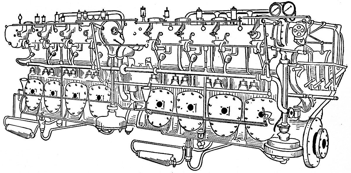
The Engine Room of a Modern Submarine Showing the Diesel Engines |
82 |
A Bliss Torpedo with Rotary Compressed Air Motor |
98 |
A 3½ inch Submarine Gun in Action Showing the Deck Well and Manner of Operation |
118 |
The Latest Type of Periscope. A much Magnified Image of the Object Is Shown in the Inner Circle, while in the Outer Circle Is Shown the Object Plus an “all round” View of the Horizon. A Submarine Fitted with This Periscope May well be Said to Have Eyes in the Back of its Head |
136 |
A Marine Wireless Installation |
150 |
The Crew of a Submarine (Note Sailor Going Below through Hatch in After-deck) |
166 |
A German U-Boat “Breaking Water” Preparatory to Examining the Cargo of an Enemy ship |
178 |
Three Eighty-Foot Gasolene Chasers on their Way to Patrol Duty |
188 |
Navigating the “Deutschland” by Means of the Deck Control (Note Open Hatch Leading to Conning Tower) |
202 |
The outcome of the great war that is now being waged in Europe hinges largely on the ability of the Central Powers[1] to sink the ships of the Allies[2] by means of submarines, and of the Allies to destroy the enemy U-boats,[3] as the German submarines are commonly called.
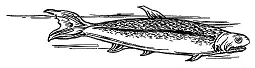
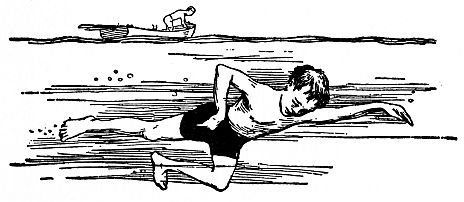
Now, while a U-boat is a submarine, all submarines are not U-boats; for the word submarine means any and everything that lives, is done, or works beneath the surface of the sea. Thus, a fish is a submarine, and so is a boy while he is under water—though his clothes may be on the shore.
How the Submarine Came to Be.—Yes, the fish[2] of the Paleozoic[4] era, see Fig. 1, was the earliest submarine, in that it moved in and through the water under its own power, and that was millions of years before the human race and the monkey tribe branched off from a common ancestor.
Not only has the shape of the fish—or ichthyoid form, as it is called—served as a model for inventors of the submarine boat to go by, but the air-bladder in the fish, which aids it in keeping its place below the surface of the water, finds its counterpart in the ballast tanks of the modern submarine.
When the first real boy parted from his monkey cousin—that is, when the boy came down from his tree-top house and left the monkey up there to eat a banana all alone—Nature had fitted him with long legs and flat feet so that he might swiftly run away from his enemies on land.
But in those days when the earth was young there were not only gigantic, long-necked animals with cross-cut saw tails and cunning little heads, but terrifying[3] winged lizards[5] flew around everywhere like airplanes do now, and monstrous and inconceivable things swam in the sea. He could easily outwit and outdistance his animal foes on land, but he could not fly away from those that sailed the air, nor could he venture far into the water for fear of his aquatic enemies. But he learned to swim in spite of them and when he could dive down here and come up over there he became the second submarine. (See Fig. 2.)
From the time he learned to swim and grew to be a man he nursed the idea of making some kind of device that he could get into and swim about with, not only so that he might be protected from the monsters that sought him as food but that he might destroy them as well.
And even after all the prehistoric beasts became extinct and so were no more on the face of the earth to menace his safety, he still kept thinking over the idea[4] of the submarine, and it kept getting stronger within him as the convolutions of his brain grew deeper.
The Development of the Submarine.—By hard thinking and long experimenting, and the other way about, and always working to the end that he might invent some kind of boat by which he could travel under and through the water (or, as the French have it, sous marin—sous meaning under and, of course marin means sea) like the swiftest of fish and quite as easily.
His reason for wanting a submarine boat now that the animals he had so feared in the past had disappeared, was to find treasure ships that had sunk to the bottom of the old ocean, or, more likely because it seemed more practical, to attack, unseen and without warning, merchantmen that carried precious cargoes—in a word, he would a submarine pirate be.
But like everything else that needs mechanical devices and electrical apparatus the development of the submarine from the first crude attempts to the powerful and perfectly controlled U-boat as we know it to our sorrow to-day took many men working through many years to make it sea-worthy and practical.
In each one of these inventors the thought that ruled him was to make a boat which would sink or swim, as he wanted it to; and though none of the earlier workers succeeded in building a really good submarine, it was not their fault but their misfortune, for the vital mechanical and electrical appliances they needed had yet to be invented.
But the efforts of each one of these pioneers served[5] as a stepping-stone to the building of the first practical boat, in 1901, which could be used successfully as an undersea destroyer. This was the Holland, which you will read more about presently; and the British Admiralty purchased five of the first ones built.
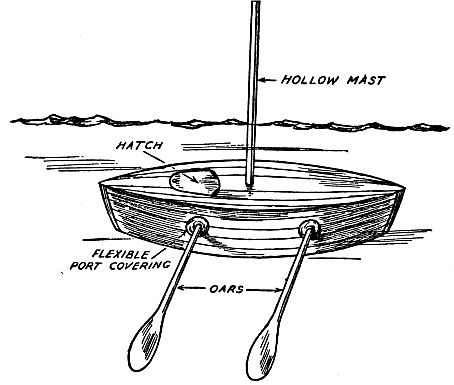
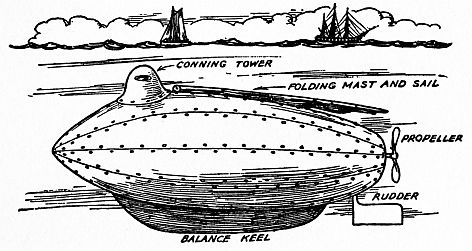
The First Submarine Boat.—Away back there in the very year when the Pilgrims landed from the Mayflower on Plymouth Rock—that is to say, in 1620—a Dutchman named Van Drebel, who happened to be living at that time in England, worked out the idea that originated in the brain of his prehistoric ancestor, and that was to build a submarine boat.
Of course in those days there were no such things as steel boats, nor had engines to propel them been invented, but men were adept builders of wooden boats and, as much or more to their credit, they were past masters of the art of sailing them.
But the lack of steel, of engines, and of other recent inventions didn’t daunt the dauntless Van Drebel in the least; for he went right ahead and built his underwater craft of such materials as he could get hold of. His submarine was nothing more nor less than a regular wooden boat which was completely decked over, covered with leather, and smeared with tallow to make it watertight.
The submarine was propelled through the water by means of a pair of oars on each side as shown in Fig. 3, very much in the same fashion as were the far-famed Grecian galleys of old; but in this boat the oars[6] passed through watertight flexible covers fastened over the portholes.
A hollow mast was stepped into the deck to supply air to the crew when the submarine was under water, and it was also used to spread a little canvas on when the boat was running afloat and the wind was good.
Now, you may think this submarine of Van Drebel’s was a mighty crude attempt, and no one will say you nay, but just bear in mind, please, that it was the granddaddy of the modern submarine and that it traveled submerged down the Thames River, carrying in it no less a personage than King James the First, and covering a distance of seven miles from Westminster to Greenwich.
After this first and very successful attempt at submarine building it was not long until others began to make improvements and to build underwater boats which would outdo the spectacular performance of Van Drebel’s submarine. It ought to send a thrill of pleasure through you to know that most of these inventors were Americans, but in your feeling of pride don’t forget that the oversea workers along submarine lines followed closely on the heels of our own in ingenuity, building, and operative ability.
A Submarine of the Revolution.—The first submarine designed to destroy enemy ships was invented and built by an American named David Bushnell, just about the time that Liberty Bell was ringing out the Independence of the United States.
His submarine, had it not been for an accident, and of which I will tell you later, would now be exploited in every school history of our country. But even the accident showed that the submarine had great inherent possibilities and dynamic power stored up in it which warring nations of the future must reckon with.
Different from all past ideas and present conceptions of submarines, and far removed from any design which is ordinarily thought of in connection with boats, Bushnell’s submarine, instead of going through the water with its long axis horizontal to the top, moved through it vertically.
The way in which this strange craft was submerged—that is, sunk—is fundamental, which means that it[8] is the simple, natural way and the one that is used in all submarines that have been built since then.
A number of empty tanks were so fixed in the vessel that when the pilot wanted to submerge it he could let the water into them, and when he wanted to rise to the surface again he could pump the water out with a hand force-pump. This scheme is used in all of the submarine boats of the present time, though of course the pumps are power-driven.
A heavy weight that could be detached was fixed to the bottom of the craft, which helped it to maintain its upright position and also aided in submerging it. In case an accident happened to the pumps the weight could be released, when the craft would come to the surface.
Another good feature of this submarine was the valves which let fresh air into the vessel when it floated on top of the water but which closed automatically—that is, without the help of the pilot—when the submarine sank below the water line.
The way the first submarine of Bushnells was driven was just as primitive as the one built by Van Drebel; indeed, it was a shade worse, for a solitary oar sticking through the rear end of the shell provided the means for going ahead while another oar on one side helped to raise and lower it.
He later designed, built, and successfully operated another submarine, which was far superior to his first model. It had the same shape as his first one but it was propelled by two screws which were turned[9] by hand; one of these moved the submarine forward and backward through the water, and the other one moved it up and down—all of which is clearly shown in Fig. 4. Hence the credit for the invention of the screw-driven submarine belongs to Bushnell.
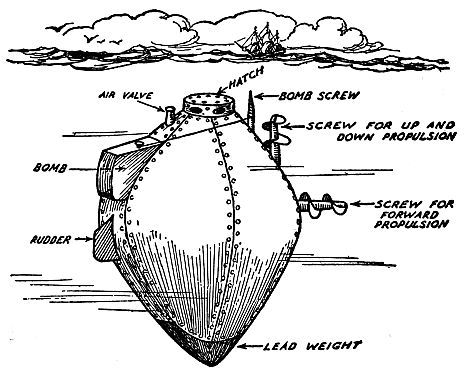
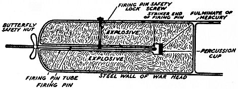
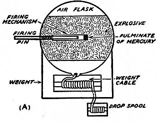
The First Torpedo Fired by a Submarine.—Bushnell, though, did more than to invent a workable submarine, for he also devised and used a torpedo; or it would be better to call it a bomb, since it was timed to explode by clock-work, instead of by concussion. He intended to hang this submarine bomb on the bottom of an enemy ship—and thereby hangs a tale.
The British man-of-war Eagle had anchored in New[10] York Harbor close to Staten Island sometime in the famous year of 1776.
The inventor was a patriot and offered his services and the use of his submarine to the new United States Government; the latter accepted them and ordered him to blow up the warship. As the inventor became sick he gave a sergeant, named Lee, the honor of using his submarine and blowing up the ship. Lee worked the submarine without a hitch until he reached the man-of-war, and then his troubles began.
Try as he would, he could not drive the screw into the tough English oak of which the hull of the ship was made, and this he must needs do in order to fasten the bomb to the bottom of it.
Finally, just as the clock-work of the torpedo was about to explode it, he set it adrift, and the young officer made off just in time to save himself. As it was, the bomb exploded close to the stern of the boat, but it did not do any serious damage.
Robert Fulton’s Submarine.—About the year 1800, Robert Fulton, the Famous American inventor, who built the first successful steamboat, designed and built a submarine that was far ahead of either of those I have just described.
It was cigar-shaped, to begin with, and this lessened the resistance it offered to the water, and it was fitted with a keel, a rudder, a propeller, and a conning tower, so that the pilot could see where he was going. Fulton did not attempt, though, to use a steam engine to drive[11] the propeller, but turned it by hand. His submarine is shown in Fig. 5.
Another big improvement that Fulton made was to cover the hull of his submarine with copper plates. Taken altogether it came as near being a real submarine as could have been made with the materials and inventions which were available at that time.
After offering his submarine to the French, British, and American Governments in turn, and after it was turned down by all of them because they failed to see in it a useful weapon of war, Fulton turned his thoughts toward home and craft of a more peaceful nature.
Had any one of these governments been able to see the wonderful possibilities of the undersea craft that Fulton had so greatly improved upon, the submarine would have been perfected long before it was.
Fulton’s remarkable experiment, with his Nautilus, as he called his boat, on the Seine River, which flows[12] through Paris, attracted much attention, and a plan was set on foot to use his submarine to rescue the exiled Napoleon from the Island of St. Helena. Again Fulton was doomed to disappointment, for the Great Emperor died before the scheme could be carried out.
It was then that Fulton returned to the United States and set about the more peaceful task of building a steam propelled river boat, or steam boat as it is called, and which won for him much money and undying fame.
The Earliest Steam Propelled Submarine.—It was eighty years after Fulton made his classic underwater experiments that Garrett, an English inventor, designed, built, and operated a submarine which used steam as its source of power.
This later submarine had all the good features of Fulton’s craft, besides the history-making improvement of using a steam engine to drive her—not only when she was afloat but when she was submerged as well.
The way it was done was like this: a regular boiler was set in the boat and this had a telescopic funnel, as a ship’s smoke-stack is called. When running on the surface the water in the boiler was changed into steam and the smoke poured out of the funnel. But when the craft was submerged, the funnel was drawn under the deck, the fire doors, which were made air tight, were closed, and the steam pressure already generated in the boiler was high enough to run the boat for several miles.
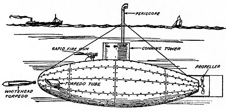
The Coming of the Torpedo-Tube Submarine.—Clear up to the time of the Centennial Exposition held at Philadelphia in 1876, the only idea that inventors of submarines seem to have had was to use a bomb of some sort which could be attached to the submerged hull of an enemy ship and which would blow her up.
This crude scheme, as you have seen, was not only uncertain but it was at once a difficult piece of work and very dangerous to the operator. About this time, or perhaps a little later, a Swedish engineer, named Nordenfelt, invented a torpedo which could be shot from a tube in the head of the submarine.
His early submarine had a length of 100 feet and could make 12 knots[6] on top of the water; she could be submerged to a depth of about 50 feet, when, of course, her speed was considerably reduced. She was steam-driven and had two propellers.
But the great improvement of this submarine craft over all the others that had been built before her was her torpedo tubes through which torpedoes[7] could be shot from the inside of the boat and aimed at the enemy. Besides the torpedoes, she carried two rapid-fire guns, and these made her an engine of destruction greatly to be feared. She is shown in Fig. 6.[14]
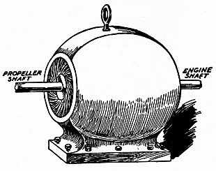
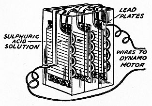
The Invention of the Electric Submarine.—What with the amazing uses to which electricity was being put, it is small wonder that as soon as the storage battery was invented and electric motor was discovered,[8] inventors became imbued with the idea of using the mighty invisible power for running their submarine boats.
The first submarine to be propelled solely by electricity was designed and built about 1886 by Campbell and Ash, of England. The outstanding features of this undersea craft were the storage batteries, which were formed of 104 cells, and the electric motors, of which there were two and each one developed 45 horsepower.
The boat had a speed of 6 knots, and it had a cruising radius of 80 miles, without recharging the batteries. She is shown in Fig. 7. The electric submarine never got out of the experimental class, because of the imperfections of the storage battery at that early[15] date and in virtue of the fact that its range of travel was very limited.
But the experiments were not without value, though, for they led to the use of electricity as the ideal power for undersea propulsion, as you will presently learn.
What the Gas Engine Did for the Submarine.—Greater effort to use electricity as a motive power for submarines would doubtless have been made had not the gas-engine been invented in 1888.
This new kind of engine was the ideal motive power for propelling a submarine on the surface of the sea, and at the same time it could drive a dynamo which would generate an electric current to charge the storage batteries with.
And when the boat was submerged the engine could be stopped and there was no smoke or burnt gases to escape; the storage battery then gave up its electric current, this energized the motors, and these in turn drove the propellers. This combination system of gas and electric power is used in all submarine boats at the present time.
The first engineer to combine a gas and an electric power plant in a submarine as described above was Depuy de Lôme. This French engineer turned out a wonderfully successful submarine; and this was still further perfected by another Frenchman, named Gustave Zédé. Many of the submarines used in the French Navy at the present time are of the Depuy de Lôme-Zédé type.
The Two Types of Submarines.—Two American inventors, name Lake and Holland, were working independently of each other—that is, neither knew the other was working on submarines—and each developed a different type of undersea boat. This was about 1896.
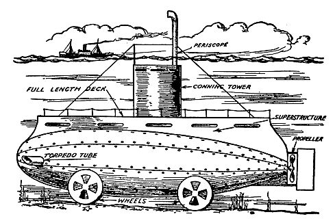
The Lake Submersible.—The first underwater boat built by Simon Lake was shaped very much like a ship. The hull was mounted on wheels, so that it could travel on the bottom of the sea if need be, for it was originally intended to be used by pearl divers and oystermen.
In the early part of this chapter I told you that the word submarine means anything that lives in, is done, or works beneath the water-line of the sea. Now, in naval engineering, submarine has come to mean an undersea craft that can dive, while an undersea boat that simply sinks on an even keel is called a submersible. So the Lake shown in Fig. 8 is a submersible, for it is not intended to dive.
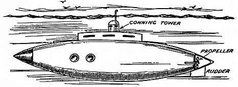
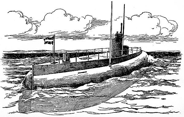
The Holland Submarine.—The Holland undersea boat is a real submarine, for it can dive. The hull[17] of this boat looked more like a whale with its tail twisted up than like a boat, as you will see in Fig. 9.
The Combined Holland and Lake Types.—The
shape of the Holland submarine makes it a good undersea[18]
[19]
boat; the Lake submersible has a large deck
and roomy quarters, and its shape makes it good for
surface going. The result is that naval architects
have combined the two types so that the new model
submarines have the advantages of the older types and
are without their disadvantages.
Nearly all of the boats of the submarine flotilla of the United States Navy are of the Holland and Lake types combined, as shown in Fig. 10. You will find more about these craft in another chapter.
The best way to know how a machine works is to work with it, and the next best thing to working with an actual machine is to work with a model which you have made with your own hands.
In this way you not only will become acquainted with the mechanism which is used to obtain a certain result, but if you are of an inventive turn of mind you are likely to get one or more ideas for improving it which will be of more or less value.
Now, this is just what you should do with the submarine if you really want to know the innermost secrets of how it is made and works—that is, you should build a model of one and experiment with it.
To the end that you may do this, I have given in this chapter the plans and specifications, which mean the working drawings and a full description, of a 2-foot model submarine boat which you can easily make and run yourself.
This model submarine is not only instructive but it is “amoosin’,” as Artemus Ward used to say, for while it starts out awash—that is, with its deck just about level with the top of the water—it will soon[24] take a dive, run a ways submerged, and then bob up on the surface again, just like a real submarine.
The Parts of the Model Submarine.—There are only four chief parts to this model, and these are (1) the hull; (2) the ballast tank; (3) the power plant; and (14) the superstructure. All of this is shown in Fig 11.
The hull is of course the body of the boat. The ballast tank is a tin can in the bottom of the hull; when it is filled with water the extra weight makes the boat sink, and when the water is blown out of it by compressed air it makes the boat rise to the surface again.
The power plant includes an electric motor, the batteries to run it, the propeller-shaft and propeller, the pulleys which work the valve that lets the compressed air flow into the ballast tank to blow out the water, and finally the superstructure, which consists of the deck and the conning tower, though in this case the latter is made to hold the compressed air.
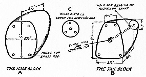
The Hull of the Boat.—The first thing to do is to make the hull; and the easiest way to build one that is light, strong, and watertight is to whittle out, or have sawed out, two tapering pieces of wood as shown at A and B in Fig. 12. The faces are shown by the dotted lines at C and D in Fig 11.
These are for the nose and tail blocks, as we will call them, and each one is 14½ inches long. The other dimensions, as well as the shapes of these blocks, are also shown in Fig. 12.
Bore four ⅛-inch holes, ¾ inch deep in the faces—that is, the flat ends of each block—at the places shown by the little circles; these are to take in the ends of the brace rods. Next bore a ¼-inch hole lengthwise through the tail block as shown by the dotted lines at B. Bore out this hole with a 1-inch bit to a depth of ¾ inch, to form a stuffing box.
Now cut off a piece of brass tube which has an inside diameter of ⅛ inch and an outside diameter of ¼ inch and force it into the hole in the tail block; this tube forms the bearing for the propeller-shaft.
Cut out a disk of brass 1¼ inches in diameter and 1/16 inch thick; drill a ⅛-inch hole through the center of it for the propeller-shaft to pass through, and three ⅛-inch holes at equal distances apart near the edge, as shown at C, so that it can be screwed to the tail block. The purpose of this disk is to keep the packing in the stuffing box. See Fig. 12.
The next thing to do is to cut off two brass rods each ⅛ inch in diameter and 16½ inches long and fit the ends of these into the lower holes in the blocks; and then cut off two more brass rods 17 inches long and set these into the upper holes. Bend these latter rods out a little until the faces of the blocks are parallel with each other, and you will have a substantial framework on which to fasten the skin of the hull.
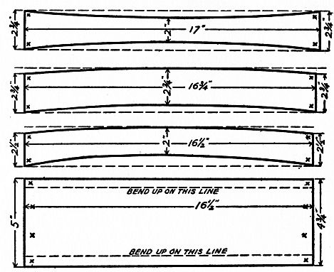
The skin, as the sheets or plates which form the hull are called, is made of sheet tin, and to cut the tin you should have a pair of tinner’s shears.
You will need seven strips of tin altogether: one for the bottom and three for each side. The sizes and shapes of these strips are shown in Fig. 13. The widest strip is used for the bottom of the hull; bend up the edges along the dotted lines, then punch eight holes in the ends—these are shown by the little crosses—and screw it to the nose and tail blocks with flat-headed wood screws.
Next punch holes in and screw one of the lower strips to each side of the nose and tail blocks, with the hollow curved edge down and lapped over the turned-up edge of the bottom strip; punch and screw on each of the middle strips, with its lower hollow curved edge over the top of each of the lower strips; and then punch and screw on the top strips.
When you have the bottom and all of the side strips screwed on, each one will lap over the next lower one ½ inch and fit snugly up to it, and at the same time they will all curve gracefully.
After you have these strips screwed on, you must solder the lap seams to make them watertight. You can easily do this by using a regular tinner’s soldering copper—a soldering fluid made by dissolving zinc clippings in some dilute muriatic acid—and what is called wire solder.
The cover of the boat, or deck, to give it its nautical name, is a part of the superstructure, and you can cut this out later on.
The Ballast Tank.—The sole purpose of the ballast tank is to add enough weight to the boat to sink it when you want it to sink.
Use heavy sheet tin for the tank. Cut out two strips, each of which is 2 inches wide and 15½ inches long.[29] Make a ½-inch lap seam and solder the ends of this strip together, making one strip 30 inches long. Bend the strip so that each side is 11 inches long and the ends are 3½ inches long; this will bring the ends together, forming another ½-inch lap seam, and this, of course, you must also solder.
Cut out a top and a bottom, each 4 inches wide and 11½ inches long. Cut the corners; bend up the edges ¼ inch all round, and solder the corners. And don’t be afraid to use plenty of solder, for this tank must be strong, and not only watertight but airtight as well.
About 4 inches from one end of the bottom sheet cut a ½-inch hole for the water inlet and outlet, that is the hole where the water flows into and out of the tank. In this hole solder a piece of ½-inch brass pipe ½ an inch long and flush with the surface of the tin, as shown at A in Fig 14; and also at B in Fig. 11.
Now, with a pair of dividers 1¾ inches in diameter, scribe a circle which has its center 3¼ inches from the other end of the bottom and in the middle of it. Cut out three strips of tin ¼ inch wide and 2 inches long—or wire will do—and bend over one end of each one ¼ inch.
Solder these strips to the bottom at equal distances around the circle as shown by the dotted line at B in Fig. 14, and in the cross-sectional drawing Fig. 15. The upright strips serve as guides to keep the cork float in place and yet let it move freely up and down in the tank.
Cut a hole ½ inch in diameter, 2 inches from one end of the cover, or top, of the tank as shown at A in Fig. 14. This is for the pipe of the valve mechanism.
Next cut out a hole exactly ¾ inch in diameter, and have its center 3¼ inches from the end. Take a piece of tin and make a valve seat so that its small end is 9/16 inch in diameter and solder it to the top over the hole. This valve seat must be made with particular care, so that it will be perfectly smooth and the valve plug will fit it airtight.
The valve plug is a piece of cork cut in the shape of a cone and must fit the valve seat exactly; soak it in machine oil, then run a piece of aluminum wire 1¾ inches long through it and bend it over on the bottom as shown at C in Fig. 14 and in Fig. 15.
Next solder the bottom to the sides of the tank.
Drop the cork float between the upright guides as[31]
[32]
shown at B in Fig. 14. Set the cork valve plug on the
cork float. Put on the cover with the aluminum wire
sticking up through the hole in the valve seat; and
finally solder on the cover.
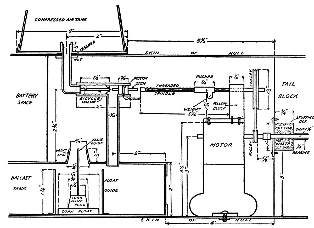
The Air Control Mechanism.—Since you cannot be in your model submarine when it is stealing along submerged through the water, you must fit an automatically controlled air-valve in the pipe that connects the air chamber with the ballast tank, in order to blow out the water when it is time for the craft to come to the surface to breathe again.
There are two chief parts to the air control mechanism, and these are (1) the air-valve, and (2) the pusher control. We will describe the air-valve and its fittings now and tell you how the pusher control is made and works under the next caption.
The Power Plant.—The reason we have split up the air control mechanism in this fashion is because it is easier to solder the air supply pipe to the ballast tank at this stage of the work than it is to do it after the ballast tank is fixed to the bottom of the hull; again it is easier to do the latter job before the power plant is put in the hull; and finally the pusher control is really a part of the power plant.
If you will take a good look at the cross-section drawing, Fig. 15, you will see that the air-valve and its fittings consist of (a) the air-valve proper; (b) a small piston; and (c) the connecting pipes.
First get four lengths of pipes[9] all of which have an[33] inside diameter of 5/16 inch; have these pipes ½, 2, 2⅜ and 2¾ inches long respectively. Thread or have these pipes threaded as follows: the ½-inch length threaded inside and all the way through; the 2-inch length of pipe threaded on the inside to a depth of 1 inch from one end and a hole drilled in it ⅝ inch from the other end, and have this threaded; the 2⅜-inch pipe threaded on both ends and one end bent over ⅝ of an inch; and, finally, thread one end of the 2¾-inch length of pipe.
Now screw the ½-inch length of pipe on the end of the 2⅜-inch piece of pipe which has the nut and washers on it. Screw a bicycle tire valve into the 2-inch piece of pipe and far enough in so that the bent end of the 2⅜-inch pipe can also be screwed in, as shown in Fig. 15. Last of all, screw the end of the 2¾-inch pipe into the threaded hole in the wall of the 2-inch pipe.
Next make a piston of a piece of brass rod ⅜ inch long and of such diameter that it will fit snugly and yet slide easily in the end of the 2-inch pipe. Drill a 1/16 inch hole through the piston and fix a stem in it tight so that it projects ¼ inch through one end and ⅜ inch through the other end. File a grooved ring around the piston to hold in the oil and slip the piston in the open end of the pipe.
This done, clean the lower end of the long pipe[34] well; set it into the hole in the top of the ballast tank; use plenty of soldering fluid and solder it in good and tight. At the time you are doing this job see to it that the long pipe sets plumb—that is, perfectly straight up and down.
Setting the Ballast Tank in the Hull.—You are now ready to set the ballast tank in the hull. To do this you must cut a hole ½ inch in diameter, 4 inches from the face of the nose, as shown at B in Fig. 11. Set the tank in the hull so that the pipe on the bottom of it will stick through the hole which you have just cut; and then solder the pipe to the hull on the outside.
Putting in the Bulkhead.—As you will see from the end views C and D in Fig. 11, there is considerable space between the ballast tank and the skin of the hull on both sides.
As melted lead is to be poured into this space to give the boat the right weight to make it sink properly a bulkhead—that is, a partition—must be cut out of tin and soldered to the hull, on the inside of course, up against the rear end of the ballast tank. The face of the wooden nose against which the ballast tank rests will keep the lead from running out at the front end. As the lead is poured in after the motor is set in place this operation will be described later.
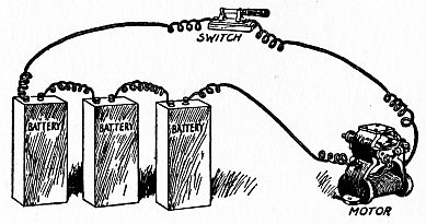
About the Power Plant.—While in a real submarine the power plant—the machine that converts the fuel into power to drive the boat—is a gas engine when it is cruising on the surface, and a storage battery and an electric motor when it is running submerged, in[35] your model it is electricity first, last, and all the time.
That is to say, a battery of dry cells supplies the current to run an electric motor and this in turn drives the propeller; besides, it also furnishes the power needed to work the pusher which controls the air supply through the bicycle valve which I have just explained to you.
The first thing to do toward getting the power plant is to beg, buy, or borrow a small electric motor which will develop not less than 1/30 horsepower and at the same time run on a battery of not more than 3 dry cells.[10]
While the motor can be run to its full capacity on two dry cells it will develop more power on a three-cell battery. Now, to get three dry cells which will fit into the small space that is left in the hull of your model you will have to use rectangular cells.[11]
You will also need a small switch to open and close the battery circuit, and this is fixed to the top of the boat, or deck as it is more properly called; the way it is put on will be explained under the caption of The Superstructure.
When you want to buy one of these switches ask for a porcelain base, single pole, single throw switch. It will cost about a quarter. The way the dry cell battery, the motor, and the switch are connected up is shown in Fig. 16.
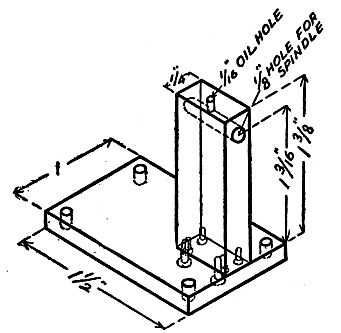
The Pusher Control Device.—Before the motor is installed in the hull the pusher control device which opens the compressed air valve must be made and mounted on top of it.
On top of the motor, as you will see by looking at Fig. 16, there is a metal name plate, which is fastened to the top of the field magnets by four screws; unscrew the latter and take off the plate.
Now make a pillow block, as the bearing for the threaded spindle is called. Saw out with a hack saw[12] a base plate of sheet brass ⅛ inch thick, 1 inch wide, and 1½ inches long; drill four ⅛-inch holes in the corners of the plate, so that it can be screwed down to the field magnets of the motor.
Also drill two ⅛-inch holes lengthwise in the middle of the plate and have the first one ⅛ inch from one end and the other ½ inch from the same end and in a line with the first hole.
Take a brass bar ¼ inch thick, ½ inch wide, and 1⅝ inches high, and drill two 3/32 inch holes in one end of it, to correspond to the two holes in the middle of the base plate, and thread these to fit a couple of 6-32 machine screws.
Next drill a ⅛-inch hole clear through the top of the bar, or standard, as it is now called, 3/16 inch from the top. This must be very accurately done, in fact, it ought to be done with a drill press, for if it is not precisely at right angles to the base, the spindle will not run true, and besides there will be a great loss of power.
Drill a hole through the top of the standard until it meets the hole through which the spindle is to pass, and by means of this top hole keep the spindle well oiled. The pillow block is shown complete in Fig. 15 and 17.
To make the spindle, get a piece of soft steel rod ⅛ inch in diameter and 4½ inches long. Thread it from one end to within 1⅜ inches of the other end, and screw on a nut as far as it will go. Push the smooth end through the hole in the pillow block; slip a collar over the end close up to the standard, and screw it fast. To make the pusher mechanism complete put a grooved pulley 1½ inches in diameter on[38] the end of the spindle up close to the collar and screw it fast.[13]
The last part of the pusher control is the pusher itself. It is simply a round brass rod ¼ inch in diameter and ¾ inch long, with a hole drilled through it lengthwise and threaded to fit the spindle. Solder a bit of brass near one end, to make it heavier on one side than on the other.
Now, when the motor is set in place in the hull and its small pulley is belted to the large pulley on the spindle and the current is turned on, the spindle revolves, but the weight on the pusher will keep it from turning with the spindle. Instead, the curious result[39] is that it screws itself toward the free end of the spindle, and when it reaches the end, the hollow pusher goes over the stem of the piston. When it strikes the piston it pushes on it until it presses the other end of the stem against the pin of the bicycle valve and this opens it.
If you will keep the piston, the pusher, and the bearings well lubricated with sewing-machine oil, there will be little power lost through undue friction. But you must be careful not to get any oil on the commutator of the motor, for this will keep it from running properly.
The Propeller-Shaft.—Before you install the motor you must put the propeller-shaft through its bearing in the tail block.
To make the propeller-shaft, get a piece of soft steel rod ⅛ inch in diameter and 5¼ inches long and thread it at both ends. Slip it through the tube which forms the bearing. Soak some cotton-waste in machine oil and pack it in the stuffing box in the tail block. Now screw the circular plate to the face of the tail block to keep the packing in place.
Installing the Motor.—While we have given you the height to make the pillow block, it will, of course, depend on (1) the height of the motor, and (2) the height of the center of the piston when both are measured from the floor of the hull; this is because the pusher spindle and the piston stem must be exactly in a line with each other.
Another thing: The motor we have shown is 3[40] inches high from its base to the center of its armature shaft; but the motor you get may not be of this height. While it can’t be any higher than 3 inches unless you change the design of the boat, it can be shorter if you mount it on a block of the right thickness.
Before installing the motor in the boat, see that both pulleys are in a line with each other, and put on a belt. Thread the end of the motor-shaft and fit a coupling to it so that the propeller-shaft can be screwed into the other end. To make the coupling take a piece of brass rod ¼ inch in diameter, 5/16 inch long; drill a 3/32-inch hole in it, and thread it to fit the motor- and propeller-shafts.
Screw the coupling on the motor-shaft. Mount the motor on a board of the right thickness, and set it in position in the hull. Screw the propeller-shaft into the coupling, and be sure to have the motor set so that the shafts are in perfect alignment—that is, in a line with each other—as shown in Fig. 15.
Unless this is done the propeller-shaft will bind in its bearing and it will take a large part of the power of your motor to overcome it. When the motor, the pusher spindle, and the propeller-shaft all spin freely on closing the battery circuit, you can then secure the motor to the floor of the hull with a couple of machine screws as shown in Fig. 15.
Ballasting the Boat.—The next thing to do is to ballast the boat by pouring melted lead into her hull to make her sink deep enough in the water to balance[41] her and to make her submerge entirely when water is let into her ballast tank.
The way to do this is to cork up the hole in the pipe in the bottom that leads to the ballast tank and then set the boat in a tub full of water. Now lay the battery cells in the positions they are to occupy in the boat, as shown at B and C in Fig. 11, and see how far up the water-line comes on the hull—or, in other words, how deep the hull sinks into the water.
Next pour melted lead in between the sides of the ballast tank and the hull while the boat is still in the tub of water and distribute it so that the boat floats on a perfectly even keel. When you have poured enough lead into the hull to make her sink to within an inch or so of her gunwales (the upper edge of the boat’s sides) and she is nicely balanced, let the lead cool, take the boat out of the tub and put her back on her stocks on your bench.
And now a couple of parting hints: (1) You can melt the lead in an iron ladle over a kitchen fire, and (2) put a little water in the ballast tank so that the hot lead will not open the soldered seams.
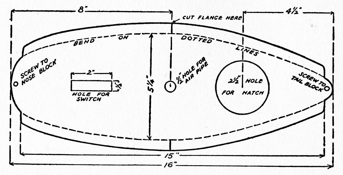
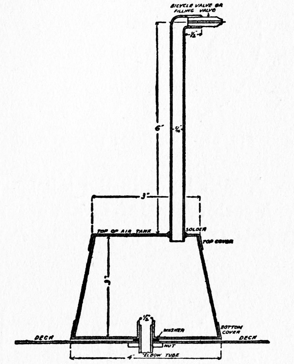
Making the Superstructure.—This consists of the top, or deck, and the conning tower, which in this model serves for the compressed air tank.
To make the deck, cut out a sheet of heavy tin the exact shape of and dimensions given in Fig. 18. Cut a ½-inch hole half way between the ends, and in the middle, for the air-valve pipe to pass through and[42] which is screwed to the conning tower as shown in Fig. 15.
Cut out a 2½-inch hole in the aft end of the deck for a hatch, and make a cover, or hatch, for it 3½ inches in diameter; this hatch will allow you to get your hand through the deck and into the hull to reset the pusher device when your submarine is to make another trip.
Cut out a rectangular hole ½ inch wide and 2 inches long in the for’ard end of the deck, for the screws and the wires of the switch to pass through. Screw the porcelain block of the switch to a board of the same size, with the tin deck in between them; this insulates the screws of the switch from the tin, which would otherwise short circuit the battery and run it down. Run sealing-wax in and around the edges of both the porcelain and wood blocks to make a watertight joint, for water must not get into the boat.
This done, connect up the batteries and these with[43] the motor, with heavy rubber-covered copper wire, and connect the battery and the motor with the switch with flexible electric-light cord. Set the deck on the hull; and if you are sure everything is in first-class working order, solder it on tight. If, though, you are not quite certain, you can do a temporary job by putting it on with sealing-wax.
Supposing you are young enough to have imagination or old enough to have dim vision, the switch mounted on the deck will look very much like a gun that is just coming through the hatch and getting ready for action.
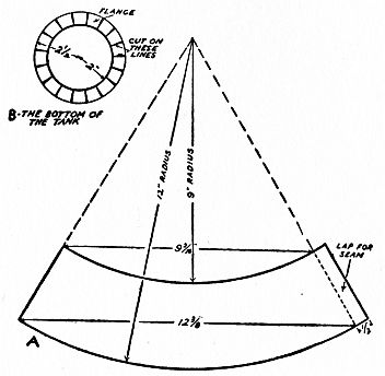
And Now the Conning Tower.—The conning tower is an airtight vessel—as far as your model goes—having a conical shape.
To make it, scribe two circles, using the same center, on a sheet of heavy tin, making one of them 4 inches in diameter and the other 5 inches in diameter, and cut it out around the larger circle.
Cut a ½-inch hole in the center of the disk. Put the ½-inch length of threaded pipe we told you about under the caption of The Air Control Mechanism in the hole, and solder it fast. Cut the edge of the disk radially with your shears, from its edge to the smaller scribed circle, and then you can bend up the edge all the way round.
Next cut out an arc of tin of the size marked and the shape shown in Fig. 19. Make a lap seam and solder it.
Scribe a 3-inch and a 4-inch circle on a piece of[44] tin and cut it out. Cut the edge radially as before, and bend it up all the way round. Cut a ½-inch hole near the edge of the intake air-valve pipe. Solder the two disks to the cone and be sure the ½-inch threaded pipe is inside.
To complete the conning tower, get a 5- or a 7-inch length of pipe; bend over one end a little; thread it and screw in a bicycle valve. Finally stick the other end of the pipe through the hole in the top of the conning tower and solder it there, as shown in Fig. 20, which also shows the conning tower complete. The purpose of this pipe is so that you can pump air into the tank with a bicycle, or an auto pump.
Screw the conning tower on the end of the pipe of the air-valve mechanism which projects through the[45] top of the deck, and then you are ready to do something else.
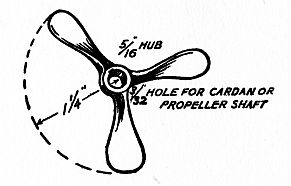
Setting the Propeller.—A 2½-inch brass propeller with three blades can be bought for about 40 cents of Luther H. Wightman and Co., 132 Milk Street, Boston, Mass.
This little propeller has a hub diameter of 5/16-inch, as shown in Fig. 21. When you get it, drill a 3/32-inch hole through the hub and thread it; screw it on to the end of the propeller-shaft, and then screw on a nut to hold it on tight. (See Fig. 22.)
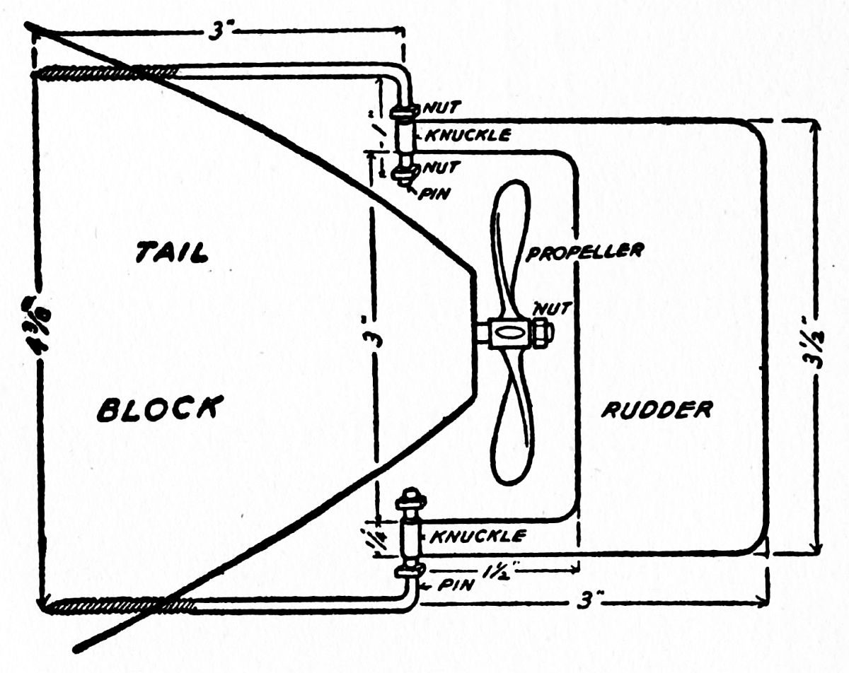
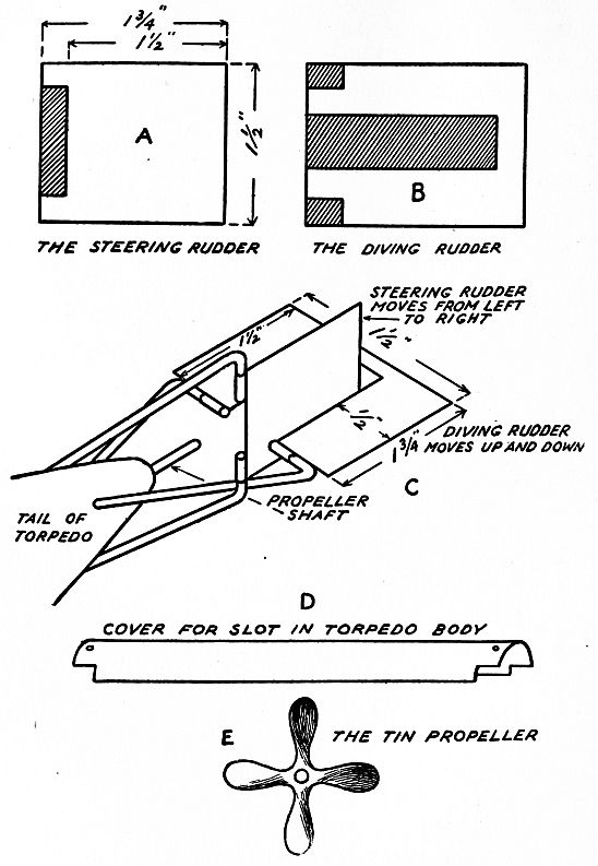
Putting on the Rudder.—And last of all comes the rudder. Cut off two pieces of ⅛-inch brass rod[46] 4 inches long; thread one end of each rod down 1 inch, and sharpen the end a bit; thread the other end of each one down ⅝ inch and screw a nut on it.
Drill two 3/32-inch holes in the tail block in a vertical line with each other 4⅜ inches apart, and screw in the brass rods as shown in Fig. 22. Cut the rudder out of heavy tin—or, better, 1/32-inch-thick sheet brass—the size and shape shown also in Fig. 22.
Bend the end of each tongue of the rudder to make[47] a knuckle, and slip the knuckles over the pins. Screw a nut on the end of each pin, and by tightening them up you can make the rudder stay at any angle you put it.
Painting Your Craft.—You can buy a good marine paint of almost any color you want at paint stores generally.[14]
Gray is the most appropriate color to paint your model craft with; but whatever color you choose, lay it on the long way of the boat so as not to streak it but make a good smooth job of it. Put on three coats and let each coat dry thoroughly before you apply the next one. And now your submarine is done, and if you have made a good job of it, it will look like the half-tone cut shown here.
How to Work Your Submarine.—Having everything in readiness, take your terrible little U-boat under your arm to the nearest lake or river.
Pump the conning tower full of compressed air and then gently put her in the water. Throw on the switch, and it will do the rest. By this, I mean that the moment you turn on the current the motor will drive the propeller at a goodly clip and the craft will travel over the surface of the water awash—that is, with the water washing over her deck.
At the same time, the ballast tank begins to fill with water, and the added weight makes the boat go deeper[48] and deeper until only the bridge[15] of her conning tower can be seen; and after a few moments more her periscope (or air supply tube) sinks out of sight.
While she is going down the weighted pusher is moving slowly but surely over the threaded spindle; when it reaches the piston it pushes it against the pin in the air-valve and so opens it and keeps it open.
The instant the air-valve opens, the compressed air from the air tank (conning tower) rushes into the ballast tank, and because it is under a high pressure it forces the water out of the tank through the hole whence it came in.
When the water has been blown out of the ballast tank the boat is, of course, lighter, and naturally she rises to the surface again. This is your cue to be right there with a rowboat and get her and to pump more air into the compressed air tank before she makes another trip.
If you don’t do this and she ever goes down with her ballast tank full of water and there is no compressed air left to blow it out with, you can send a censored report to the daily papers that another U-boat has been sunk and that there was no time to save the crew.
But, anyway, you will have oceans of fun with your model, and your head will brim over with submarine lore.
As we told you in the first chapter, there are two kinds of undersea boats. These are (1) the Holland, or submarine type, and (2) the Lake, or submersible type. Now, the Holland boat has a shape very much like a cat-fish—that is, it has a blunt round head—and hence it can dive easily; while the Lake is shaped more like an ordinary boat and has a large superstructure, as that part above the hull[16] is called, and this makes it easier for the Lake to submerge—that is, sink on an even keel.
As the art of undersea boat building moved on apace, the two kinds of craft began to lose their original distinctive features and were merged into a single type. This was done to get a boat that was as strong and as speedy as and could dive like the Holland, and to have at the same time a boat that was as fast and as seaworthy on the surface as the Lake.
This is the reason that most of the undersea craft of to-day are a cross between the two kinds. In the older boats, though, the difference is still marked; but the machinery of both is just about the same, and[52] consequently what we shall tell you of one is just as true of the other, and from now on we shall call both kinds simply submarines.
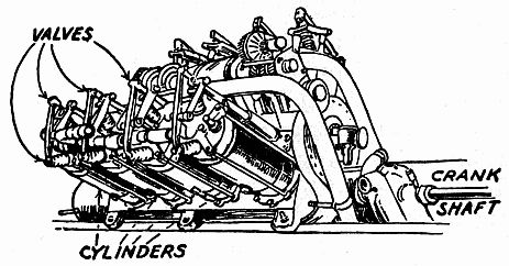
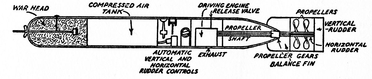
The Parts of a Submarine.—To begin with, a submarine is formed of: (1) the hull; (2) the superstructure, which is built on the hull; (3) the steering apparatus, which includes the submerging and diving devices; (4) the power plant, which consists of the engines, the dynamo-motors, and the storage batteries, all of which drive the submarine when it is on the surface and under the water-line.
As the power plant is a most important part of the anatomy of a submarine, it will need a whole chapter to describe it the right way, and this will come next. Now I’ll start in and tell you about the other parts of the submarine.
How the Hull Is Made.—The hull is made of thin but very strong sheets of steel riveted together. As the pressure of the water on it amounts to 187 pounds to the square inch, at a depth of 300 feet, it must be well braced or else there would be the unpleasant possibility that it might be crushed in. As a rule, though, a submarine never travels at a depth much greater than 100 feet.
Now, there are really two classes of submarines: (a) those that are built for coast patrol cruising, and (b) those that are built for trans-oceanic going.
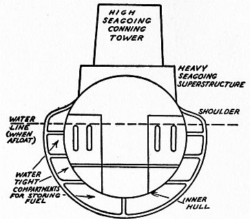
A submarine of the first kind seldom has rough weather to contend with, and so she need not be built as strong as one that is designed for ocean[53] going. She also has a slightly different shape from the latter, in that she has a round cross-section, as shown in Fig. 23.
By looking at Fig. 24 you will see that the ocean-going submarine is more nearly half-round; this tends to prevent her from rolling unduly. She also has a double hull which is divided into watertight compartments to protect her from sinking should an enemy ship ram or fire on her. The compartments are used as stowage tanks for fuel, etc., and so the space between the inner and outer skins, as the hulls are called, is not wasted.
A large number of fittings are fixed to the hull, such as the diving and steering rudders (all of which will be described later), while the superstructure is built on top of it.
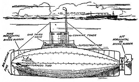
What the Superstructure Is.—The superstructure consists of (1) the deck and (2) the conning tower. In the Holland submarine the deck is only about one-third as long as the boat and this allows it to dive easily.
The Lake boat is decked over nearly the whole length of the hull. In it are fitted rapid-fire guns which disappear, and there are watertight ventilators which let in fresh air when the boat is traveling on the surface. Further there is a hatch—that is, an opening in the deck with a watertight door—through which the torpedoes can be lowered into the hold of the submarine.
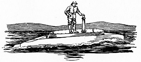
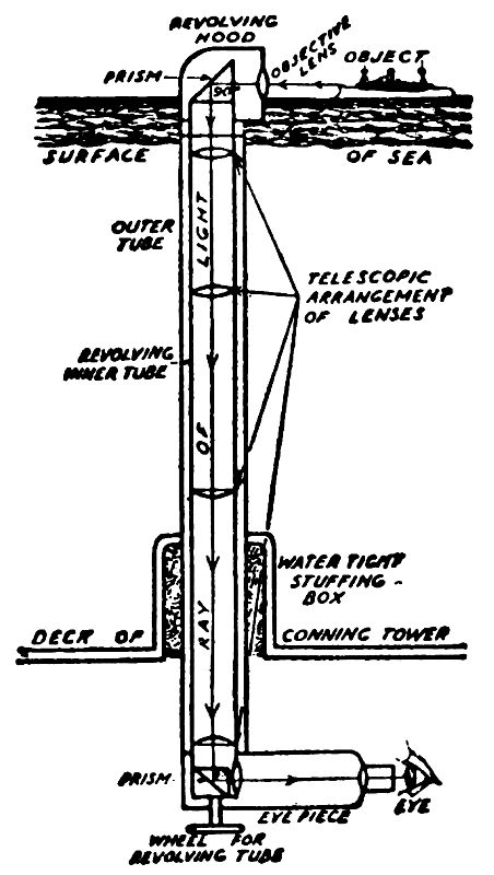
The Outside of the Conning Tower.—From out of the center of the deck rises the conning tower. This[55] is a heavily armored, shell-proof, circular structure, from which the captain makes his observations and sends his orders down into the engine-room and controlling compartments. On the bridge or upper deck of the conning tower is a hatch by which the crew can get into and out of the boat.
A steering wheel and compass are fixed to the outside of the conning tower, and the submarine can be steered by these when it is running on the surface. A stanchion for carrying the signal lights is also secured to the conning tower; while the periscope, or eye of the submarine, passes through the bridge and to one side of the hatch. Of this wonderful instrument we shall have much to say a little further on.
Wires, or stays, as they are called, fore and aft are used to brace and hold the periscope and signal stanchion firm against the force of the water which presses on them when the craft is submerged and under way. The tops of the signal stanchion and the periscope are also braced by a signal halyard, which is simply a wire, or cable, stretched taut between them.
On all modern submarines a wireless aerial is attached to a mast which can be folded down flat on the deck when the submarine is getting ready to make a dive.
A Look Inside of the Hull.—Now let’s take a look inside of the submarine. The whole hull is divided up into a number of watertight compartments, any one of which can be shut off from the others and so lessen the danger of sinking by ramming or by shell-fire,[56] should the boat be afloat. In these compartments are placed all the machinery and the controls for operating the submarine.
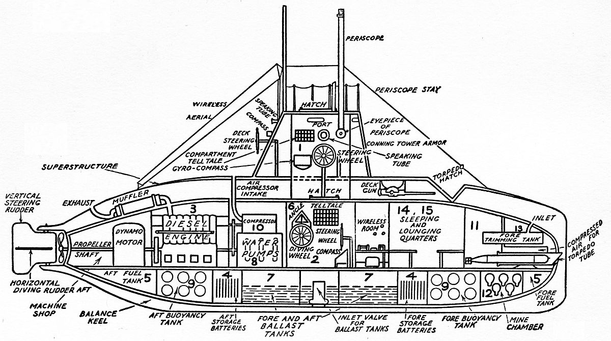
These various compartments are: (1) the conning tower; (2) the navigating compartment; (3) the engine and dynamo room; (4) the fore and aft storage battery rooms; (5) the fuel tanks; (6) the diving control compartment; (7) the fore and aft ballast tanks; (8) the water pumps; (9) the fore and aft high pressure air flasks; (10) the high pressure air compressor; (11) the torpedo compartment; (12) the mine compartment; (13) the trimming tanks; (14) the quarters of the crew; and (15) the quarters of the officers. All of these are clearly shown in Fig. 25.
The watertight doors of these compartments are worked by worm gears, driven by electric motors, as shown in Fig. 25, and any of the doors can be opened or shut by merely throwing a switch.
A Peep into the Conning Tower.—The free space inside of the conning tower is not more than 8 feet in height and 10 feet in diameter.
Sticking down through the deck for about 2½ feet is the periscope, or two of them, for all submarines now built are fitted with a pair of them so that should one of them be hit and put out of business the other will be available.
This instrument is formed of a long tube with a
hood at the upper end, which is outside of the conning
tower, and an elbow at the lower end, inside of the
tower. An eye-piece is fixed to the lower end, so that[57]
[58]
the captain can scan the horizon at all times. How
a periscope is made and used will be described in a
later chapter.
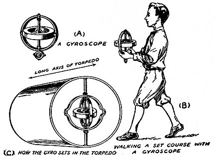
Just below the eye-piece of the periscope is the underwater steering wheel, and close to and to one side of the latter is the underwater compass. In the more recent submarines a gyroscopic compass[17] is used as well as the regular magnetic compass because the gyroscopic compass is not affected by stray magnetic lines of force. Besides, a gyro compass, as it is called for short, points to the true north instead of to the magnetic north pole, and a true compass is of the greatest importance in guiding the submarine at night or when it is submerged, for it is then as blind as the fish in Mammoth Cave.
Around the inside of the tower near the bridge are placed ports through which the captain makes and takes his observation when the boat is afloat. Within easy reach of his mouth are speaking tubes which lead to the engine, diving, and torpedo compartments. The captain also has at his finger-ends an electric signal system of lights and bells, which he operates by push buttons and switches.
So you see he can get into instant touch with all the vital parts of his boat. He also has full control over the trimming tanks and the storage batteries, both of which I shall tell you about in detail presently.
Right in the line of sight of his eyes is a depth meter by which he can see at a glance at just what depth his craft is moving, and he can also see at what angle[18] the diving rudder, or elevator, as it is called, is set.
A compartment tell-tale (a numbered chart showing each compartment of the boat) also hangs in sight, and if a compartment should begin to leak it is instantly indicated by the tell-tale, which in this case is a miniature electric lamp that lights up back of the number.
By pressing a button he can ring an electric bell in the leaking compartment and so warn the crew that he is about to close the electrically operated bulkhead door and so shut the compartment off from the rest of the boat if the damage done is so serious that it cannot be repaired.
Now the Navigating Compartment.—As you have read before, the conning tower is not a part of the hull but of the superstructure. Now, when the captain or any of his crew wants to get from the conning tower into the hull of the boat he must do so through a hatch in the lower deck which is exactly like the hatch in the top or bridge of the tower.
This arrangement makes it easy to shut off the conning tower into the rest of the boat if it should be seriously damaged by shell-fire or by collision. Should this happen, the boat is steered from another compartment[60] called the navigating room, in which are all of the devices used in the conning tower. So you see there are two complete navigating rooms and an outside deck control by which the submarine can be steered and operated, no matter how badly damaged she may be.
Next, the Diving Control Compartment.—The compartment containing the diving control, by means of which the submarine can be made to dive and to come to the surface, is fitted with the following devices:
First, there is the diving wheel, which works the horizontal or diving rudders.
Next, there is the angle indicator, which is simply a quadrant—that is, a quarter of a circle—marked off into degrees and each degree into quarters. It has a needle which moves over the quadrant as the pilot turns the diving wheel and this indicates the number of degrees up or down the horizontal rudders have moved.
Another instrument is the depth indicator.
Then there is also an indicator which is merely a modified form of a carpenter’s spirit level. This little device shows when the craft is running on an even keel and when it is running with its keel inclined. For instance, should the diving rudder fail to respond to the touch of the man at the wheel, the level would indicate it, as would also the depth indicator.
Other fittings are the levers and the valve controls, by means of which water can be let into the ballast tanks.
Now, before I explain how the submarine is made to dive and how the ballast tanks work, or, rather, the other way about, I want to tell you a little about the why and the wherefore of these very interesting operations.
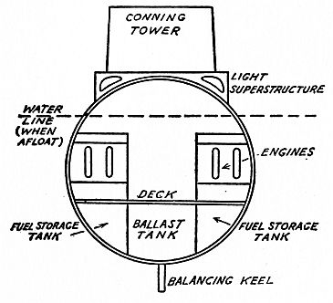
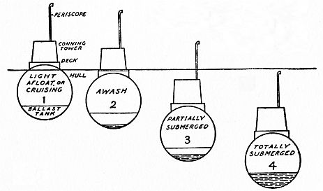
The Four States of the Submarine.—A submarine has four states, or conditions, in which it exists in the water. These are (1) the light, or surface cruising condition; (2) the awash, or partly submerged condition; (3) the submerged condition; and (4) the totally submerged condition—all of which is clearly shown in the diagram Fig. 26.
The Light Condition.—The light, or cruising, condition is simply the position a submarine takes when she floats on the water, due to her own natural buoyancy, and it is exactly like that of any other ship.
While in this position the captain takes his observations[62] from the deck, if there is no danger of being hit by the enemy; but if there is danger, he then makes his observations through the ports from the inside of the conning tower.
The Awash Condition.—This condition is not as natural as the one just described, and it has to be done by means of the ballast tanks. These are located fore and aft and they can be connected with, or disconnected from, each other at will.
Now, when the captain wants to bring his submarine to the awash condition an inlet valve, or Kingston valve as it is called, is opened and the sea-water then flows into these tanks, the amount and velocity of the inrushing water being, of course, under control at all times.
This extra weight destroys part of the buoyancy of the boat, and as she gets heavier she sinks until nothing but her conning tower remains above the water-line, the deck being awash. While in this condition observations are taken either from the ports in the conning tower or with the periscope, the object-glass of which has been lowered enough to become useful.
The Submerged Condition.—In this condition the periscope alone remains above the water. It is had by allowing more water to flow into the ballast tanks, thus destroying a little more of the craft’s buoyancy, which makes her sink down until the conning tower is completely submerged. It is in this condition that the captain makes his observations with the periscope.
The Totally Submerged Condition.—This is an exaggeration[63] of the submerged condition, and it is had by letting still more water flow into the ballast tanks, thus sinking the submarine completely. The only way to steer the boat when it is in this condition is, of course, by means of the compass, for both the conning tower and the periscope are totally submerged.
But do not mistake the term totally submerged to mean that the buoyancy of the submarine is totally destroyed; for such is not the case during any stage of its submergence. You can easily see that if the buoyancy were completely destroyed the submarine would then become a dead weight and sink to the bottom of the sea, never more to rise.
Instead, when the submarine is totally submerged she can, by what is known as her reserve, or extra buoyancy, and about which you will read later on, come to the awash or the light condition in a few minutes by simply pumping the water out of the ballast tanks.
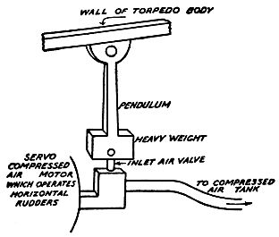
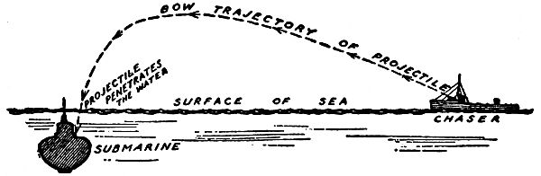
How a Submarine Dives.—Now let’s get back to the way a submarine dives. In the first place, let us suppose the boat is running in the light, or cruising, condition. An enemy ship is sighted and the captain of the undersea craft gives orders to clear the deck and close the hatches. Then he brings the boat from the cruising to the awash condition, which is done as we have just described.
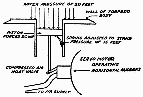
Next, he gives the order to the man at the diving wheel to make the dive. He does not need to do this by word of mouth but he can use an electric indicator[64] which points out the angle at which he wants the horizontal rudders set (see Fig. 27). Contrary, now, to what you might expect, a submarine cannot dive at any angle, but it must make a very shallow dive.
So when the order is given, the diving rudders are set at only ½ a degree from the horizontal, as shown in Fig. 28. The craft must move through the water at about 5 knots, which is the proper diving speed.[65] When the conning tower is one-fourth submerged the angle of the rudders is increased to 1¼ degrees.
This angle is held until the conning tower is half submerged; and then the angle is changed to 2 degrees, and it is held there until the conning tower is three-quarters submerged. As soon as this takes place, the angle is decreased to 1¼ degrees again, and the rudders remain at this angle until the dive is completed.
Why a Shallow Dive Is Made.—The reason such a shallow dive must be made is the result of having to let water into the ballast tanks to bring the craft to the awash condition before diving.
If the angle of the dive were to be suddenly increased to 10 or 15 degrees the tilting of the boat would throw all the water forward in the tanks and this would seriously upset her balance, and might even make her settle nose downward to the bottom of the sea.
How the Boat Is Kept Submerged.—When a dive is to be made the diving rudders are set at the angles just mentioned, but water is not let into the ballast tanks at the same time, for this would also tend to destroy the balance of the boat.
But when the captain wants to keep his submarine at a certain depth below the surface of the water after the dive is made he has water admitted to the ballast tanks and this keeps her at that level. When he wants to return to the surface, or “break water,” the water is pumped out and then the diving rudders are set and the boat makes an upward glide.
The Time It Takes for a Dive.—The time needed for a submarine to get ready to dive is about 2 minutes; but this is often long enough for it to become a target if a submarine chaser is on the little war-dog’s trail. Should she be hard pressed she might dive at a steeper angle—say, 5 degrees, but never more, and under ordinary conditions she will never dive at more than 2 degrees’ inclination.
The reason it takes time for a submarine to get ready to dive is because the wireless masts have to be folded in, the machine guns disappeared, and the hatches fastened down. Finally, it must not be forgotten that a submarine can dive only when she is pushing ahead under power. If she is at rest and the captain wants her to sink he must either start her engines or else be content to simply submerge her on an even keel.
The Ballast Pumps and What They Do.—The pumps which pump the water from the ballast tanks are driven by electric motors. They must be powerful pumps, for they not only have to pump the water out of the tanks quickly, but they have to force it out against the pressure of water in which the submarine is submerged; this pressure increases the deeper the boat sinks, and it is often 80 pounds or more to the square inch. The pumps are controlled from the conning tower, and also from the navigating compartment.
What the Buoyancy Tanks Are For.—We said previously that a submarine never loses its buoyancy[67] completely. If she were built like an ordinary ship and simply fitted with ballast tanks, she would sink when these are filled with water and never come up again, for her natural buoyancy would be destroyed. As it is, a submarine has tanks filled with air which keeps her buoyant, and these will bring her to the surface the moment the ballast tanks are empty.
Make this experiment and you will quickly understand how these buoyancy air tanks work: Take an empty bottle and cork it up tight. It looks empty, but as a matter of fact it is filled with air. Push the bottle to the bottom of a bucket of water; let go of it and the instant you do so it will rise to the surface.
A large number of steel air tanks, or buoyancy tanks, or high pressure air-flasks, as they are called, are placed both fore and aft in a submarine, and these are filled with compressed air at a pressure of 2,000 pounds to the square inch. These air-flasks have a tremendous supporting power—which is only another way of saying that they are extremely buoyant.
It must be clear now that even though the submarine is resting on the floor of the ocean it can always rise to the surface by the reserve buoyancy provided by these air-flasks.
Compressed Air and Air-Compressor Pumps.—The air-flasks are filled with compressed air by air-compressor pumps which are driven by the engines when the submarine is running light or awash.
The air compressor is formed of several air pumps coupled together; each air pump is made very much[68] like a water pump, but it sucks the air in from the outside and then forces it into the air-flasks until it is under a pressure of 2,000 pounds to the square inch. To overcome this back pressure, as it is called, the pumps must be extra powerful.
These pumps also supply compressed air for the torpedo tubes, the trimming tanks, and to help blow out the water from the ballast tanks.
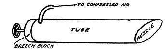
Inside the Torpedo Compartment.—The torpedo compartment contains the extra torpedoes in their cradles. Near the tubes from which the torpedoes are shot is the compressed air which furnishes the propulsive power needed to make the torpedoes leave their tubes.
Why Trimming Tanks Are Used.—As a torpedo weighs nearly 1,000 pounds, it is plain that whenever one is shot from the craft it will very greatly disturb the balance of the boat unless some means is used to add weight to it which is exactly equal to the weight of the torpedo.
This is done by what is called the trimming tanks. These are usually placed fore and aft and in or near the torpedo and mine compartments. As soon as a torpedo is shot, or a mine is laid, the trimming tanks are filled with water which makes up for the weight lost and keeps the craft on an even keel.
If, on the other hand, any extra weight is taken aboard the submarine, enough water to equal it is blown out by compressed air.
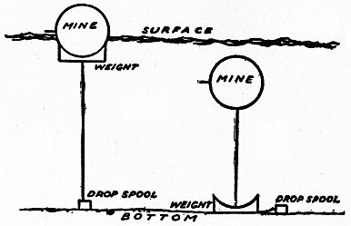
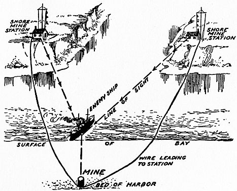
In the Mine Compartment.—The mine, as the[69] stationary bombs that are to be laid in a harbor or some other strategic point are called, are kept in the mine compartment.
This compartment has a trap door in it through which a mine-layer, that is a man dressed in a diving-suit, can get out of and back into the submarine again, or through which the mines can be lowered.
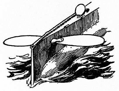
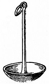
And Last of All, the Sea Anchor.—A submarine must have an anchor as well as a merchantman. The anchor is of the mushroom type, so called from its appearance; and as you will see from the accompanying picture (Fig. 29), it is very different from the two armed and fluked kind that so resembles an Irishman’s anchor i.e., a pickax.
Where the Crew of a Submarine Lives.—Proper quarters for the officers and crew in the earlier submarines were sadly neglected; but conditions have[70] greatly changed since then—though of course they are not quite so good as living in a luxurious hotel ashore.
Great improvements have been made in behalf of the undersea navigators and sailors, until in the more recent submarines the crew have quarters that compare favorably with those on board a battleship.
There are oxygen tanks that supply pure air, while electric fans set up a forced draft and keep the air cool and make it circulate freely. Then there are electric heaters which keep the temperature just right under all conditions.
It goes without saying that the modern submarine has its galley—that is, its cook room. But, very different from the galley on the old windjammers that used to sail the seas, the sea-cook does not use a cook-stove, which was also called a galley, but electricity.
Since the time of the first propelled underwater boat great strides have been made in the methods of driving the submarine, until at the present day the power plant seems to be well-nigh perfect.
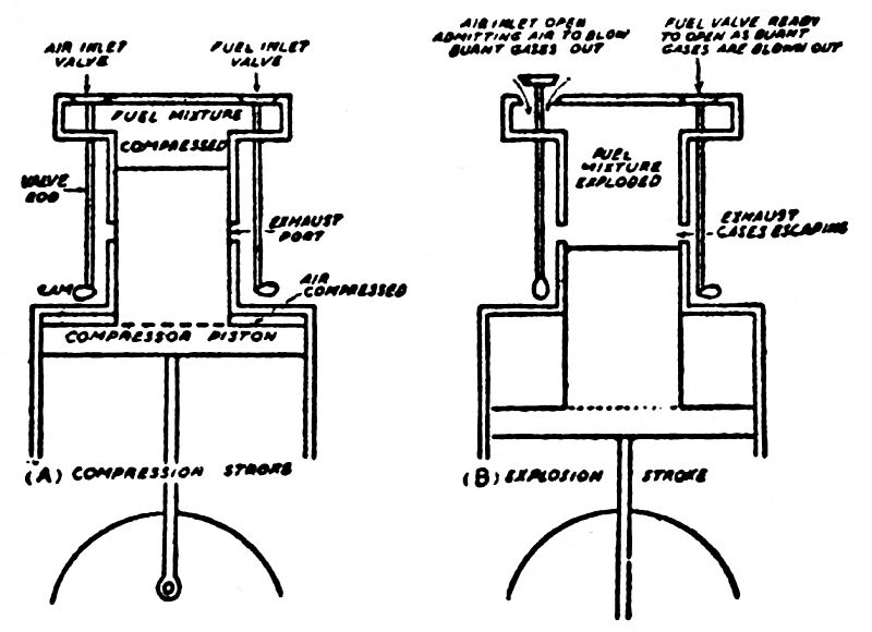
As the steam engine was improved upon, its value for driving submarines became better thought of by inventors, not because it was at all suitable for the purpose, but in virtue of the fact that it was the first and for a long time the only practical scheme to produce power on a large scale. For this reason, all the early and even some of the later submarines were powered with steam engines.
What a Good Power Plant Is.—There are certain things an engine must be and do to make it useful for driving a submarine boat, and among the chief ones are:
(1) It must be as small and as light as possible and still have great strength.
(2) It must develop a lot of power for its size and weight.
(3) It must use a small amount of fuel for the power it develops.
(4) The fuel it uses must not be bulky for the power it gives.
(5) It must not give off odors.
(6) All working parts must be easily getatable, and
(7) It must not give off poisonous gases, or vapors that ignite easily, for either of these are dangerous.
From this you will see that it is not an easy matter to make an engine for a submarine that will have all of these good features, but inventors have come pretty close to it, as you will presently learn.
The Faults of the Steam Engine.—Now while the steam engine was the only motive power that could be used in the early submarine for driving it when both afloat and under water, it lacked nearly every one of the good features named above; for,
(1) While a steam engine can be made light and strong, a large heavy boiler is needed, and this makes the boat a very hot and unhealthful place for the crew; (2) it is very wasteful of fuel, for most of the heat energy[19] that is stored up in the coal or oil is lost before it ever reaches the engine; (3) if coal is used, it is too bulky, and if oil is used it is too liable to give off vapors which will catch on fire and explode.
These untoward features did not matter so much when the submarine was afloat, but when she was cruising below the water they were all present to make life miserable for the crew. But when the storage battery[75] was put into such shape that it could be used, all this was changed and the conditions were so improved that undersea travel became bearable and pretty safe as well. We will tell you all about the storage battery and how it develops power a little further on.
When the Gasoline Engine Came.—The next improvement in submarine power plants came when the gasoline engine was made practical.
This new kind of a prime mover[20] was so much better in every way than the steam engine that nearly all submarines now built are powered with them in one form or another.
The usual kind of gasoline engine is known as the four cycle type and has from 12 to 16 cylinders, the pistons of each of which are connected to one crankshaft, and together they form a power unit, as the complete engine is sometimes called.
A submarine engine of this kind can develop upwards of 5,000 horsepower and the large units weigh close to 100 tons. Except that it is larger and is built especially to meet the needs of the submarine it is exactly like a motor car or an airplane engine which is shown in Fig. 30.
How the Gasoline Engine Works.—A single cylinder gasoline engine is easier to understand than one with four or more cylinders, so I’ll describe it first.[76]
It consists of (1) a cylinder with valves in it and in which a piston moves to and fro; this is connected to (2) a crankshaft by means of (3) a piston rod as shown in Fig. 31. To the cylinder is fixed (4) a carburetor which mixes the gasoline with the air and forms the explosive gas, or fuel mixture as it is called, and (5) a high tension magneto which generates an[77] electric current to make the spark that fires the fuel mixture, etc.
It is easy to understand how a gas-engine works if you will just remember that for every power stroke there are three other strokes, making four strokes altogether, or four cycles as it is called.
The power stroke of the piston is the stroke made by the explosion of the fuel mixture and this forces the piston down. This is the stroke that turns the crankshaft one-half of a revolution and gives it force enough to carry it around until the next power stroke takes place. Thus the flywheel of a single cylinder four-cycle engine makes two complete turns or revolutions to each power stroke of the piston.
Fig. 31 shows how the inlet and exhaust valves are worked, each one by a little wheel with a lump on one side, or cam, as it is called, which is fixed on a cam-shaft and is turned by the crankshaft. The cams, of which there are two for each cylinder, are set directly under the ends of the valve rods, and as the cam-shaft revolves, the little lumps on the cam strike the valve rods at the right moments and this lets the fuel mixture into the cylinder and lets the used and burnt-up gases out of it.
Each valve is provided with a stiff spring, which, as soon as the lump on the cam has turned past the valve rod, lets the latter drop again and so closes the valve.
Fig. 31 also shows the complete action of a four-cycle engine. The suction stroke is shown at A; as the piston moves down, the cam forces the inlet valve up[78] and the piston sucks the fuel mixture into the cylinder. The exhaust valve is closed while this stroke is taking place.
The compression stroke is shown at B; the momentum, that is the stored up energy of the flywheel, carries the piston up and forces the fuel mixture into a very small space, that is, it compresses it. By this time the cams have moved past the valve rods and both the inlet and exhaust valves are closed.
The power stroke is shown at C, and this is the only one of the four strokes that actually counts. When the fuel mixture is compressed it is exploded by an electric spark and the force of the explosion drives the piston down and gives the flywheel great momentum.
It is the momentum produced by this stroke that not only furnishes enough power to carry the flywheel round until another power stroke takes place, but also furnishes the excess power to do useful work, such as to drive a dynamo or a propeller. Of course both valves are closed when this stroke is being made.
The exhaust stroke is shown at D and is one of the up strokes of the piston. The cam opens the exhaust valve and the piston forces the burnt gases of the fuel mixture out of the exhaust port, and that clears the cylinder for the next stroke, which will be the A stroke over again, and so on through the same four cycles just described.
The Carburetor and What It Does.—This apparatus is connected to the fuel tanks, which usually contains gasoline, by a supply pipe. The gasoline is forced[79] out of the tank by compressed air being pumped into the latter and thence it passes into the carburetor.
The carburetor changes the liquid fuel into a fine spray, or vapor, and mixes it with air, and this is drawn into the cylinder when the inlet valve opens and the piston is making its suction stroke.
The Magneto Electric Machine.—This is an electrical device which is simply a little dynamo. When it is driven by the engine it generates a high tension current of electricity which will jump between the ends of two wires ⅛ inch apart, and this makes a spark.
The magneto is connected to a spark-plug which is screwed into the head of the cylinder. A timer connected to the magneto and the spark-plug closes the circuit each time the compression stroke is completed; the instant the circuit is closed the current generated by the magneto makes a spark at the business end of the spark-plug and this fires the fuel mixture.
But as good as the gasoline engine is for motor cars, power boats, and airplanes, it has been found sadly wanting as a power plant for submarines; this is due not to any fault of the engine but to the explosive nature of the gasoline which is used.
Gasoline is a very volatile liquid, that is, at ordinary temperatures and pressures it tends to change from its liquid state to a vapor which is really a gaseous state. You may have noticed this if you have been near a place where gasoline is stored, for the whole air is saturated with the vapor given off by it and this is what you smell.
Further, it is quite impossible to store a fuel like gasoline, and to use it for firing an engine in such a confined space as there is on a submarine, without the air becoming charged with the vapor, which is injurious to those who breathe it, and which, should it be accidentally ignited, would explode with such force that it would wreck and sink the submarine.
The Last Word in Submarine Engines.—Having tried out both steam and gasoline engines for submarine work and both having been found wanting, further experiments were made in engine building.
Now, since it was known that the chief fault of the gasoline engine lay in the fuel it used and not in the engine itself, inventors worked hard to make an engine that would burn a fuel so much heavier and less volatile than gasoline that all danger from vapor would be done away with.
Many engines were built along this line, but all failed until Diesel (pronounced Dé-sel), a German inventor, found a way to make an engine that would burn a heavy oil. The Diesel engine is now used in every submarine that is built, nearly; and for this reason I want you to understand exactly how it is made and how it works.
How the Diesel Engine Works.—The Diesel engine works on the same general principle as the gasoline engine—that is, by the explosion of a fuel mixture in the cylinders—but it is different from the gasoline engine in the way in which the fuel is admitted into the cylinder and fired.
In the Diesel engine, a rough diagram of which is shown in Fig. 32, there are two valves in the head of the cylinder, one of which lets in the heavy fuel mixture and the other one admits compressed air to the cylinder. The exhaust valve is at the bottom of the cylinder, and the lower part of the cylinder is built to form an air compressor.
The way it works is like this:
(a) When the compressed air valve opens, the compressed air is forced into the cylinder and this drives the piston down when the valve closes.
(b) The power that this stroke gives to the flywheel forces the piston up again, and this compresses the air as shown in A, Fig. 32. Now when you compress air, it heats it, and the amount of heat developed depends on how much the air is compressed; you can even feel the heat that is set up by compressing the air in a toy pop-gun; or you may have noticed that when an automobile tire is pumped up fast it gets hot. Of[82] course, while the air is being compressed in the cylinder of the engine the compressed air valve stays closed.

(c) When the fuel inlet valve opens, the heavy fuel is forced into the cylinder by means of compressed air which presses on the fuel in the supply tank. The instant the fuel strikes the hot air in the cylinder it ignites and burns, and as it burns it expands just as the gases of burning powder in a cartridge expand. This forces the piston down and makes the power stroke as shown in B, Fig. 32.
Here, then, is another great advantage of the Diesel engine over the ordinary gasoline engine: it does not need an electric spark or any other kind of flame to fire it.
(d) As soon as the piston has reached the down end of its power stroke, the exhaust ports are opened and more compressed air flows through the compressed air valve; this blows what is left of the burnt gases out of the cylinder through the ports, and as soon as this is done the piston starts to go up, when it compresses whatever air there is in the cylinder again.
While this stroke is being made the air compressor piston in the bottom of the cylinder, which is a part of the regular piston, has been compressing the air needed to perform the above operations. Since there is only one waste stroke to every power stroke, the engine is a two-cycle one, and herein lies its third big advantage over the gasoline engine.
The reason that the Diesel engine is better adapted to burn heavier oils than the gasoline engine is because[83] the latter uses an electric spark to ignite the fuel mixture and this must be very light and volatile, since the spark is not hot enough to fire the heavier oils.
Again, in a gasoline engine the fuel mixture explodes—that is, it burns very rapidly, like the powder charge in a cartridge—whereas in a Diesel engine the fuel mixture expands when it is ignited, very much as steam expands in the cylinder of a steam engine.
Using heavy oils very greatly reduces the cost of operating an engine, for oils of this kind are usually the by-products obtained in the making of petroleum and gasoline. These heavy oils are of little value for any other purpose than fuel; and, also, since the oil is heavy, it is more easily handled than gasoline.
For these very good reasons the Diesel engine (Fig. 33), is used by nearly every government at the present time for submarine power plants. Moreover, like the steam engine, it will develop its greatest power, nearly, on starting; it does not need any reducing gears to lower its speed—this is done with a throttle as it is in a steam engine; and it can be reversed without a reversing gear, which is better than the steam engine.
The Diesel engines of present-day make range from 900 to 5,000 horsepower, and eight or more cylinders are used for each engine. The weight of the engine is about 30 pounds per horsepower; or for a 5,000 horsepower engine the weight is in the neighborhood of 70 tons. As great as this weight may seem, it is much lighter for the horsepower produced than the old-fashioned gasoline engine.[84]
[85]Why An Electric Power Plant Is Needed.—As you know, a submarine has two chief conditions, and these are (1) when it is afloat, and (2) when it is submerged.
When she is afloat the air in the craft and which the crew must breathe is being constantly sucked in from the outside, and there is always a large enough supply to keep the compartments clear and to furnish the air compressors which fill the tanks. But when the boat is submerged there is no way of getting a fresh supply unless air is taken from the tanks or the submarine goes to the surface every little while, like a whale, and this would hardly do.
The Dynamo-Motor and Storage Battery System.—When the storage battery came into use inventors of submarines were quick to see that the thing to do was to use two separate and distinct power plants and these are (1) the steam or gas engine, which is used when the boat is running afloat; and (2) the electric storage battery system, which is used when the craft is running submerged.
Three devices must be used for the undersea electric power plant, namely, (1) the dynamo, which generates the electric current; (2) the storage battery, which is charged by the current generated by the dynamo, and (3) the motor, which develops power when a current from the storage battery is made to flow through it. The diagram shown in Fig. 34 will make the electric connections clear.
About the Dynamo.—The dynamo[21] (see Fig. 34) is connected to the crankshaft of the engine and is driven by it. It changes the mechanical motion of the engine into an electric current. This electrical energy must then be stored up so that it can be used later when the craft is submerged and it is wanted.
And Now the Storage Battery.—To store up the electrical energy a storage battery (see Fig. 35) is used. When the current is made to flow into this kind of a battery it charges the battery, and if then the battery is connected to a motor it will deliver an electric current, and this runs the motor.
The storage battery has been almost as big a bugbear to the submarine builders as the oil engine. It must be as small and as light as possible; it must not absorb the oxygen of the air which the crew breathes, and it must not give off any poisonous gases.[87]
Now, there are two kinds of storage batteries, and these are (1) the lead-plate storage battery, which is the oldest form, and (2) the nickel-steel storage battery, which was invented quite recently by our own Edison. Both kinds are used in submarines.
Last of All, the Motor.—The motor is the last device by means of which the electric energy is made to drive the craft when it is undersea.
Now, a dynamo and a motor are made exactly alike, in fact, a dynamo is a motor and a motor is a dynamo. That is to say, if you turn the armature of a dynamo, it will generate a current of electricity, and if you make a current flow through the coils of a dynamo, the armature will spin round and it is then a motor.
This being true, however strange it may seem, only one electric machine is needed to do the work of the dynamo and the motor; for when it is connected to the shaft of the engine it will generate a current for charging the storage battery, and this is done while[88] the craft is afloat; or it will develop power to drive the propellers when it is connected to the storage battery, and this is done when the submarine is cruising undersea.
The submarine is first, last, and all the time an engine of death and destruction. Even in the earliest underwater experiments, you will remember, it was fitted with a bomb the sole purpose of which was to blow the enemy ship to atoms.
The old bomb idea proved next to worthless, for it was a very hard job to fix it to the ship to be sunk, and even if the submarine operator did succeed in so doing it was at best a dangerous piece of business, and so the odds for its failure were about as 100 is to 1.
As soon, therefore, as the submarine had been developed to a point where it was clear that it was the coming weapon of modern naval warfare, inventors began to rack their brains for some scheme which would do away with the danger and uncertainty of the old-fashioned bomb, and to make the submarine safer for its crew and deadlier for the enemy.
Many attempts were made, but its improvement was very slow, for the old idea of the simple bomb was firmly fixed in the minds of the inventors and it was hard for them to break away from it.
After a long time, though—that is to say in 1860—Captain[92] Lupius, an Austrian inventor, hit upon a new and novel plan for a torpedo which would travel under water, by means of a little motor in it and a pair of wires which connected it with the submarine so that it could be directed at will.
The First Submarine Torpedoes.—Lupius took his idea to Whitehead, an English engineer of genius and ability, and he built the first controlled torpedo which traveled under its own power in 1864. Then Whitehead did a little thinking on his own account and he built the automobile torpedo in 1868, the cleverest and most diabolical destroyer that man has ever yet been guilty of.
The automobile torpedo is one that not only runs under its own power but that steers itself as well after it has left the torpedo tube of the submarine. To Whitehead, then, must be given the credit not only of having invented the submarine torpedo that is used with such telling effect in the present war, but of making a success of it. The Germans, though, with their great dislike for everything of British name and make call their torpedo of this type blackheads.
How to Make a Model Submarine Torpedo.—Before I explain how a real automobile torpedo is made and works, I will tell you how to make a model torpedo which, while it will not explode at the end of its trip through the water, will show you how a real torpedo does its work.
The Body of the Torpedo.—Get a piece of nice soft pine 1½ inches in diameter and 10 inches long,[93] and whittle it out to the shape shown in Fig. 36. Cut a groove down the middle of it ¾ inch deep and ¾ inch wide, to within an inch of each end. This done, screw a small screw-eye in the warhead of the torpedo, as the blunt nosed end of it is called, inside the groove.
Bore a ⅛-inch hole through the propeller end, and slip a piece of brass tube 2 inches long which has a bore of inch in it to form a bearing for the propeller shaft. Get a brass rod 1/16 inch in diameter and 2¼ inches long; make an eye on one end and then push the rod through the brass tube in the tail or propeller end of the torpedo, as shown in Fig. 36, and this is all there is to the propeller shaft. Now cut a propeller out of tin, as shown at E, in Fig. 37, and solder it to the end of the propeller shaft.
The Steering and Diving Rudders.—The torpedo, like the submarine itself, has two rudders, one for diving and one for steering.
To make the steering rudder, which is the vertical one, cut out a piece of heavy tin 1½ inches wide and 1¾ inches long, as shown at A in Fig. 37; cut out one edge ⅜ inch deep as shown by the shaded part, which will leave a tongue sticking out from each corner, and bend these to form little tubes.
Cut off two pieces of wire ⅛ inch thick, have each one 2½ inches long, and bend them as shown at C. Next drill two holes through the tail or propeller end of the torpedo, force the sharp ends of the wires into them and then put the other ends into the tubes of the rudder.
The diving rudder, which is the horizontal one, is made like the steering rudder except that the tongues for the hinge tubes are dropped down a little and a slot ½ inch wide and 1¾ inches long is cut out, as shown by the shaded part at B.
This rudder is 1½ inches wide and 2⅛ inches long; it is fastened by a pair of ⅛ inch wires to the tail end of the torpedo in the same way as the steering rudder. This arrangement leaves enough room for the propeller to turn inside of the wires, as shown at C.
The Rubber Strand Motor.—The next thing to do is to fix one end of the rubber strands to the screw-eye in the warhead and the other end to the eye of the propeller-shaft. This gives you a cheap and simple motor that is at once light, powerful, and easy to manage.
Cut out a cover of wood to fit over the groove containing the motor, as shown in D, Fig. 37, and screw it to the body of the torpedo. Melt some paraffin wax[96] and run it around the cracks to make the motor chamber watertight.
Bore half a dozen or more holes ½ inch in diameter and about an inch deep along the exact middle of the bottom of the torpedo; fill each hole with shot and seal them in with sealing-wax. There must be enough shot in the bottom to weight the little torpedo so that it will just sink on an even keel when you put it in the water. Finally, paint the torpedo all over with black enamel (you can buy it in drug stores for 10 cents a can), and your model torpedo is ready for its deadly work.
Your Torpedo in Action.—To set your model torpedo scooting under the water and, perchance, aimed at an enemy ship, fix the steering rudder in a line with the long axis of the hull and tilt the diving rudder at a very slight angle, say about 2 degrees, down from the top of the torpedo.
Hold the hull with your left hand and wind up the rubber strand motor good and tight by turning the propeller clockwise—that is, in the direction the hands of a clock move—with your right hand. When you have done this, push the torpedo down under the water, let go of the propeller and she will shoot forward as though shot by compressed air from a torpedo tube.
After it has made a run of from 25 to 100 feet—the distance depends on the skill you have shown in building it—it will sink to the bottom.
Of course if you are playing a naval war game and you are shooting at some enemy ship, it will give her[97] a good hard bump, and this counts ten points in your favor.
How a Real Torpedo Is Made.—A torpedo, as you can plainly see, is nothing more nor less than a miniature submarine boat that moves under its own power and that is self-controlled. And now that you have built and experimented with a little model it will be easy for you to understand how a real one is made and works.
The Warhead of a Torpedo.—A real torpedo such as is shot by a submarine to sink real ships is made of three chief parts, as far as the outside of it is concerned. These are: (1) the warhead, (2) the body, and (3) the tail.
The warhead is the blunt-nosed hollow part that forms the business end of the torpedo; it contains two things: (a) the charge of high powered explosive which plays such terrific havoc when it is touched off; and (b) the detonating mechanism which fires it.
The High Powered Explosive.—The explosive used is either guncotton, or nitrocellulose, to call it by its chemical name, or tri-nitrotoluene (pronounced ni-tro-tol´-u-en) and which is called TNT for short.
Guncotton is simply ordinary cotton which has been treated with nitric and sulphuric acids; when this is done it becomes highly explosive.
TNT is toluene, a chemical formed of hydrogen and carbon, which has been treated with nitric acid. It is used by the Germans in the warheads of their submarine torpedoes because it is a more powerful explosive[98] than guncotton. Besides it can be melted as easily as lard and poured into the warhead, which makes it an easy, quick, and safe job to fill them. Further, it does not explode easily by shocks when it is transported but it instantly explodes with a detonator.
The reason these explosives cannot be ignited by fire but explode when struck a sharp tap is because they are very unstable compounds; that is, they are very easily decomposed into their original chemical parts.
Curiously enough, but by the very discovery of this advanced scientific principle men are now able to make the mightiest, which means the deadliest, explosives that the world has ever known and this makes war a thousand times as terrible now as it was in the olden days when men fought their battles at close range with their ancient lances and cross-bows.
The Detonating, or Firing Mechanism.—A modern submarine torpedo has a diameter of from 18 to 21 inches through the warhead, and this is loaded with from 200 to 330 pounds of guncotton or TNT, as the case may be.
This charge is exploded by a firing pin, or pistol, as it is called. This firing pin goes clear through the charge and into a percussion cap, which sets just back of the charge; the other and front end of the firing pin goes clear through the warhead and has a threaded end on which is screwed what is known as a butterfly-nut.
The percussion cap is simply a little copper cup and in it is placed a small charge of an explosive which[99] is easily detonated by the percussion of the pin, that is by the pin striking it. The explosive mostly used in percussion caps is mercuric fulminate, which is a compound formed of mercury, carbon, nitrogen, and oxygen.
Since it is the violent explosion of the percussion charge which strikes the main charge of the high explosive in the warhead, and the fire made by the explosion of the percussion charge has nothing to do with it, the main charge of guncotton, where this explosive is used, is often wet down with water before it is packed in, for by so doing a great deal more of it can be put in the same-sized space.
A safety pin (see Fig. 38) is set into the firing pin, so that by no possible chance can the latter pin work loose and explode the charge until it strikes the ship it is intended to destroy. Also the butterfly-nut, which I spoke of above, is used as a further safety factor.
The safety pin is simply a pin which is threaded on one end and which extends down through the steel casing of the warhead and screws into the firing pin, or pistol, and holds it securely so that it cannot strike back against the charge until it is unscrewed and taken out or broken off, when it strikes the ship.
The butterfly-nut is simply a thumb nut with a couple of wings on it. When the torpedo is shot out of the torpedo tube the butterfly-nut, which is screwed up close to the warhead on the firing pin, begins to unscrew itself by the action of the water on the wings, which now form little propeller blades; by the time[100] the nut reaches the end of the firing pin and drops off, the torpedo is quite a distance from the submarine which shot it. In this way, all danger of the torpedo’s exploding when it is in, or leaving, the submarine, is done away with. Fig. 38 shows a cross-section of the warhead and just how the detonating mechanism is made and works.
The warheads of the latest torpedoes, especially those used by the Germans, are fitted with steel cutters, so that they can cut their way through nets which ships may spread out to protect themselves.
The Body of the Torpedo.—The next part of the torpedo is the body, and there are five separate and distinct parts to it. These we have named in the order of their position, and they are,
(1) The air pressure chamber; (2) the balance chamber; (3) the power chamber; (4) the buoyancy chamber, and (5) the tail-piece which supports the propellers and the rudders.
The Compressed Air Tanks.—The air pressure chamber is simply a large steel tank and air is pumped[101] into it until it is under a pressure of about 2,000 pounds to the square inch; this means that for every square inch of the surface of the tank there is a force pressing against it of about one ton.
The air is let out of the tank through what is known as a reducing valve, which is in turn connected to the engines, and more about it will be said a little later. A reducing valve is simply a valve that regulates the amount of air which flows from the tank into the engine and keeps it at the same pressure all the time.
If the valve were not used, the air in the tank, which is at first under 2,000 pounds pressure, would drive the torpedo forward at a tremendous rate of speed at first, but as the air from the tank was used up by the engine it would lose pressure and the torpedo would soon stop altogether. But when a reducing valve is used the torpedo keeps up its same high speed until it has run its course and has either hit the ship or missed it.
What Is in the Balance Chamber.—In the balance chamber is the mechanism that controls the steering and the diving rudders, and it is these that keep the torpedo on a straight course and at the right depth under the water.
The controlling mechanism is formed of four chief devices, which are (1) a gyroscope (pronounced ji´-ro-skop); (2) a compressed air motor, which drives the gyroscope; (3) a water pressure control; and (4) a pendulum control.
The Automatic Gyro Control.—The gyroscope, or[102] just gyro, as it is called for short, is a kind of spinning top and you can buy a toy one for a quarter.[22] It is simply a heavy wheel fixed to a shaft, or spindle, and this is pivoted in a ring, as shown at A in Fig. 39.
Now hold the gyro as shown at B and give the wheel a good spin. This done, walk straight ahead, and as long as you do so you will hardly know that you are carrying the gyro, but the moment you try to change your direction you will feel the gyro twisting in your hand to counteract the movement.
This is the purpose of the gyro in a torpedo, but in this case the wheel is very heavy and it is revolved at a high speed by a compressed air motor. The gyro is[103] set with its shaft at right angles with the long axis of the torpedo, as shown at C.
Now, just as long as the torpedo moves straight ahead in its course, the gyro has no effect on it, but the moment the torpedo tries to swerve from one side to the other, or shift out of its course, the gyro pulls it back by acting on the steering rudder; it does this by regulating the air supply of a compressed air motor, called the servo-motor, and this in turn works the rudder by means of a series of levers. In this way the torpedo is automatically kept to its course.
The Hydrostatic, or Water Pressure, Control.—The water pressure control is one of the devices which keeps the torpedo at the right depth in the water.
It consists of a steel cylinder with a piston working in it. A cylinder which is open at both ends is set in the hull of the torpedo so that one end opens into the water outside. A spring presses against the piston on the inside of the hull and the water presses on the piston on the outside.
The spring can be adjusted by a screw to just balance the pressure of the water at any depth. A small valve rod is fixed to the piston, and this opens a valve which lets compressed air into a motor when the pressure of the water is greater or lesser than the pressure of the spring and this in turn works the diving rudder as shown in Fig. 40.
Suppose, for example, that the captain wants the torpedo to travel at a depth of exactly 15 feet during its whole course. The spring is adjusted to offset the[104] pressure of the water at this depth, and the torpedo is launched. Should it for any reason try to go deeper than 15 feet or to rise above 15 feet, the spring or the water presses on the piston and closes or opens the air valve of the motor, when it moves the diving rudder up or down until the torpedo is brought back to its right depth.
The Automatic Pendulum Control.—The water pressure control, however, is not enough to make the torpedo stick to an absolutely constant depth, and so to help it a pendulum control is also used.
This control consists of a pendulum which swings to and fro from fore to aft as the torpedo dives and rises, and it also starts the compressed air motor which operates the diving rudder, and this brings the torpedo back to its proper depth. It is shown in Fig. 41.
The Engine That Drives the Torpedo.—Next comes the engine that drives the torpedo, and it, too, is run by compressed air.
As I mentioned before, the air which runs it is[105] regulated by a reducing valve, but there is another important part of the power plant, and this is the heater for heating the compressed air before it is admitted to the engine.
Compressed air is as good to run an engine with as steam, for both of them have tremendous powers of expansion. As soon as the air is released from the supply tank—which keeps it compressed in a space that is many times smaller than it would take up when it is free—and has passed into the cylinders of the engine, it begins to expand, or to spread out in every direction, exactly as steam does.
Now when air is pumped into the tank it gets very hot and this heat is stored up in the air as energy; this makes the air when it is released expand with much force and gives it the power to do useful work.
But as the air is let out of the tank through the reducing valve it expands and loses its energy—or latent[106] heat, as it is called—and this makes it lose its power to keep on expanding to its greatest extent and so it gets weaker and weaker.
To overcome this bad feature of compressed air, a heater is fixed on the engine, and just as the compressed air reaches the cylinders of the engine it is suddenly heated and this gives it all the expansive force it needs. The heater consists of a small oil-burner which is so fixed that the instant the torpedo is shot from the tube an electric spark ignites the oil, and there is, in consequence, neither the loss of time nor power.
The engine is often of the cylinder and piston type and is built quite like an automobile engine, except that the inlet valve—which lets the air into the cylinders—is disk-shaped so that it can operate all the cylinders one after another. The exhaust ports open outside of the torpedo, and it sets up a tell-tale white streak of bubbles on the surface of the water.
Some torpedoes as, for instance, the Bliss-Leavitt, use a rotary engine. But whichever kind is used, the power plant develops from 30 to 50 horsepower, and thus each torpedo weighs about as much and is as costly as a high-priced motor car.
The Propeller-Shaft and Propellers.—The Propeller-Shaft.—The engine drives the propeller-shaft, or, as it is called in England, the cardan-shaft. To the end of this shaft outside of the torpedo is fixed one of the propellers.
Another hollow shaft is slipped over the first shaft[107] and one end is connected to the engine and to the other and outside end of the shaft another propeller is keyed on. This shaft is driven in the opposite direction to the solid shaft inside of it by gears that is, a set of cog-wheels.
The Propellers.—The propellers have four blades; and the reason two propellers are used is to counteract the force of each other. That is to say, if only one propeller is used, the force of the blades striking the water tends to tilt the craft to one side, and hence by using two propellers this effect is very largely offset.
The Steering and Diving Rudders.—The vertical or steering rudder and the diving or horizontal rudders are hinged to a frame around the propellers as shown in Fig. 42.
As it takes a lot of power to move these rudders against the varying water currents, an air engine must be used to work them instead of levers that are connected directly with the gyro, pendulum, or water pressure controls.
How a Torpedo Is Shot at a Ship.—And now comes the most exciting moment of all, and that is when a torpedo is shot from a submarine at an enemy ship.
The latest type of submarine usually has eight torpedo tubes, four of them fore, and four aft. These tubes are shaped as shown in Fig. 43, and are built right into the hull of the craft.
Now, when we say that a torpedo is shot from a[108] submarine we do not mean that it is fired from it, for it does not explode until it hits the ship it is aimed at, but we simply mean that it is forced out of, or driven from, the tube of the boat.
The force that drives the torpedo from the tube is our old friend compressed air, and this is taken from the torpedo air tanks of the submarine; they are placed just above the torpedo tube and are connected with the rear part of it.
Shooting the Torpedo.—Now let’s see just what happens from the moment an enemy ship is sighted up to the time the torpedo hits it and explodes.
An up-to-date torpedo makes about 40 knots, and it will travel about six miles before its compressed air is used up. But it cannot be aimed and shot with certainty at a distance of over half a mile. So when an enemy ship is sighted, the submarine creeps up upon[109] her, with nothing but her periscope out of the water, until she is within accurate shooting range.
In the meantime the speed of the enemy ship has been calculated, the depth at which the torpedo must travel to strike the ship below the water-line has been determined, and the angle, or course, the torpedo must take to hit the ship is figured out.
Due allowance must be made for the speed of the ship and the speed of the torpedo to the end that the distance both will travel in a given time may be known. Of course, if the ship is speeding along and the torpedo is shot point-blank at her it will pass a good many yards astern of her.
This operation is very much like that of rabbit hunting, in which you do not fire directly at the running rabbit, but aim several feet ahead of him, and he simply runs into the bullet or shot. So it’s all his fault if he gets killed. Just so with the ship and the torpedo; for instead of the torpedo running into the ship, the ship runs into the torpedo, and so if the ship sinks it isn’t the fault of the torpedo—or at least that is the way the German captain of a U-boat looks at it.
Before the torpedo is loaded into the torpedo tube the safety pin is taken out of the firing pin and the butterfly-nut is loosened so that it will unscrew easily. The torpedo is then slipped into the tube and the breach-block of the tube is closed. The compressed air is now turned on at the torpedo air tank; when the air rushes into the torpedo tube behind the torpedo, but the latter is kept from being forced out by a lock.
The Course of the Torpedo.—Next the captain sights his ship and finds its speed and its distance from his own craft. To direct the torpedo so that it will hit her target fairly, an instrument called a torpedo director is used. It is shown in Fig. 44, and this picture also shows how the torpedo and the ship come together.
Now as the torpedo tube is fixed in the hull of the submarine the whole craft must be turned and aimed at the enemy ship. To do this the torpedo arm of the director is set parallel with the torpedo tube; then the torpedo speed scale is adjusted at the speed that the torpedo makes and which is known.
The speed of the distant ship having been calculated,[111] the ship speed scale is set at that speed and parallel to the ship’s course, and this brings the sight arm in line with the observer’s eye and the line that the ship is sailing.
When the ship crosses the line of sight the catch of the lock is released, the compressed air blows the torpedo out of its tube, and away she goes. The instant the torpedo has left the tube the engine and other contrivances start to work and it then moves swiftly and surely over a straight course.
Long before the torpedo reaches its goal the butterfly-nut drops off, and so when it strikes the ship the firing pin which projects out of the warhead is pushed back with a deal of force and explodes the charge which either sinks the ship or cripples it.
A Torpedo with a Cannon in It.—Lieutenant Davis, of the U. S. N., has invented a new kind of warhead for torpedoes, one that is even more deadly than the style I have described.
It is made by placing a cannon in the warhead.[112] When the torpedo strikes the ship the cannon shoots a projectile clear through the hull and into the inside of the ship, where it explodes. As the projectile is fitted with a time fuse, it does not explode until it gets well into the ship, and then it does far more damage than the old-style of warhead, which explodes just as it strikes the hull. The projectile is loaded with 250 pounds of guncotton or TNT but the warhead is not loaded at all.
On the submarines that are now being built cradles which hold several extra torpedoes are fitted to the decks, and in this way the number of torpedoes which can be shot is increased.
It would naturally be supposed that a submarine carrying eight or more torpedoes is about as destructive an engine as human ingenuity could devise; but not so, for there are other munitions of warfare with which it is equipped that make it even deadlier.
Now, the word munitions means war materials of every kind—except, of course, men and money; but on a submarine the munitions are limited to (1) the automobile torpedo, which we have described in the last chapter; (2) rapid-fire machine guns, and (3) submarine mines.
In the present war Germany has undertaken the gigantic task of sinking all the merchantmen, not only of the Allies but of the neutral countries as well, and it is this U-boat policy which has brought her into a state of war with nearly every civilized country on the face of the earth.
As the torpedo is such a costly weapon, it would not do to waste it on sinking any but the largest ships, or those carrying valuable cargoes; but the same policy of Germany, which is to starve out the Allies, also calls for sinking the smaller craft, such as trawlers and unarmed[116] merchantmen, and this is done by means of rapid-fire machine guns.
These guns are mounted fore and aft on the deck of the submarine, and they are used to bring down small ships and also to enable the undersea craft to defend herself against submarine chasers, airplanes, or occasionally when she is surprised by a destroyer or other armed ship which may get within firing range and attack her before she has time to dive.
The submarine mine is as old as, or older than, the submarine boat itself; and it was probably the idea of fixing a bomb onto or planting a mine under a ship that led to the actual building of the first underwater craft.
The mine is not, however, an explosive destroyer which is used by the submarine boat; for she could never get close enough to an enemy ship in these days of electric eyes and ears to make use of one. What the submarine does do is to play the peaceful rôle of planting the mines—not with the idea of making two grow where only one grew before but of making one ship less where there was one ship more, and this is done by blowing up the enemy ships which may chance to pass over them.
Arming the Submarine with Guns.—From what has been said above, you will see that by the use of rapid-fire guns poor prizes can be easily and cheaply sunk; further, a small craft always makes a bad target for a torpedo and thus the odds of making a miss and losing a torpedo are very considerable. The use of[117] rapid-fire guns is, then, a very good stroke of business, everything considered.
Again, when a submarine is chased and has no time to dive, she is in a bad way, for she is not fast enough to escape, nor can she stop long enough to aim a torpedo at her foe. It is easy to see, then, why her armament[23] should and does include a couple of rapid-fire guns.
The Need of a Quick-Action Gun.—With these conditions staring them in the face, the designers of submarines have worked hard to equip their craft with not only rapid-firing but, what is equally as important, quick-action guns.
To get a rapid-fire machine gun was easy, for this type had been built by the Maxims these many years; but to get one that could be swung or lowered under the deck so that it would not offer resistance to the water when the submarine was running submerged, and then brought up and into action quickly, was quite a different thing, and inventors are still at work on it.
By this I do not want you to take it that submarines are not provided with rapid-fire and quick-action disappearing guns at the present time; and should you or I take a look at them we would say that they are 99 per cent. perfect and that there is no need for further improvement. But that is because we are neither designers, nor builders, nor officers of undersea[118] craft; and do not forget, either, that better things are always in order.
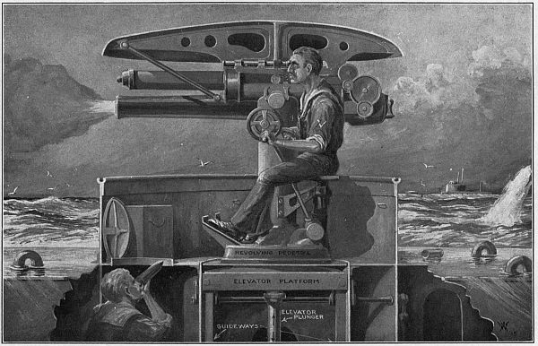
Now, there are two kinds of rapid-fire, quick-action guns used for submarine armament and these can be told from each other by the way they are brought into action. They are (1) the spring action gun, and (2) the compressed-air action gun.
The Spring Action Gun.—This type of submarine gun is made by the Krupps of Essen, Germany, who now are building the U-boats for the Central Powers.
This gun is mounted on the deck, over an opening in it called a deck-well, and this arrangement allows the gun to be stowed away in it. This is done to get rid of the resistance the water would have on the gun if it remained fixed on deck when the boat is running submerged.
Although the deck-well is closed with hatches it is not watertight, and the fittings, such as the sights and range finders, are taken off to keep them from rusting when the gun is in the well.
A diagrammatic sketch of the gun and its housing is shown in Fig. 46; the gun is mounted on a swinging frame by trunnions, and the frame is fixed to a pedestal. A strong spring in the bottom of the well supplies the power needed to throw the gun up and bring it into position.
When housed in the well the gun lays on its back, as shown by the dotted lines, and this presses down on the spring. The tension of the spring is enough to[119] force the gun up and into place the instant the catch which holds it is released.
The sights and other attachments are fixed on the gun after it is brought into position and the whole operation of raising the gun from its well and putting on the fixtures takes just 20 seconds.
These guns have a bore of 75 millimeters[24]—equal to 3 inches—and 88 millimeters—equal to 3½ inches—respectively, and the shells they use weigh in the neighborhood of 25 pounds.
The Compressed Air Action Gun.—This kind of submarine gun is used on British undersea boats. It is mounted over a deck-well but inasmuch as the gun is lowered into the well with all the fittings on it the well has to be made watertight.
If you will look at Fig. 47, you will see how the gun is brought into action. When compressed air is turned on in the cylinder, it forces the plunger on which the gun is mounted up above the level of the deck. The[120] gun is fitted with fixed sights and a range finder, and is ready for use the moment it has been brought into place above the deck, the whole operation taking only 5 seconds.
The guns of the Allies’ submarines have bores of 3 and 4 inches, and each one weighs nearly a ton. As a protection from enemy aircraft they have a wide range and can, if needs be, fire a shot at 90 degrees, that is, straight overhead.
How a Submarine Lays Mines.—The dangerous work of laying mines in an enemy harbor by a submarine is not as spectacular as torpedoing ships but it is an important part of the business of undersea craft.
A harbor which has been planted with mines to keep out enemy ships or blow them up if they try to enter it is often remined overnight by enemy submarines, and in this way a great deal of damage can be done to friendly shipping.
But whether the submarine is used for mining its own or enemy harbors, the outstanding feature of its[121] work is that it does it all under water and therefore the operations cannot be seen by spying eyes.
As we said in Chapter III, the mines are stored in a compartment in the hull of the submarine and this can be shut off from the other compartments by a bulkhead door. It also has a hatch opening through the hull to the water outside, just as the door of a kitchen opens into the back yard.
When the submarine has made its way under water to the place where the mines are to be planted, the hatch is opened and the mine compartment is allowed to fill with water. A mine layer in a diving suit can then get in and out of the flooded compartment, take the mines one by one through the open hatch, and place them in position.
Then there are mines which do not need to be set by a mine layer; these are simply dropped through the hatch into the water and adjust themselves as to depth. Other mines are made that are shot from the torpedo tubes by compressed air and these are used for mining an enemy harbor where the risks of having the submarine blown up is altogether too great to take the chance.
Kinds of Submarine Mines.—Submarine mines—that is, mines that are planted in harbors and other seaways, either as a protection from enemy ships or as an offensive measure to blow them up—really have nothing to do with submarine boats except that the latter are used to lay them. But you ought to know[122] about submarine mines, anyway, and so we’ll digress a little and tell you something of them.
First of all, there are two distinct kinds of mines and these are, (1) contact mines, and (2) electrically controlled mines.
As you can tell by its name a contact mine is one that is exploded by the hull of a ship coming in contact with it—that is, by running against it. This is the kind of mine that is most often laid by the submarine.
An electrically controlled mine is one that is exploded by electricity. For this purpose a pair of wires are connected to it and these lead along the bottom of the harbor to two observation stations on the shore; when the enemy ship gets directly over the mine the observers close the electric circuit and the mine is exploded.
This is the way the Maine was sunk in Havana harbor in 1898, but the Maine was not an enemy ship. The result of this rash bit of foolishness led to the war between the United States and Spain, and the loss of her island possessions.
How the Mines Are Made.—The contact mine.—This kind of a mine consists of a steel shell, or container, which holds the charge of high explosive, the trigger mechanism which explodes it when a ship strikes it, and the weights and cables needed to sink the mine to the right depth. Air chambers are also placed inside the container, to give the mine buoyancy;[123] otherwise it would sink at once to the bottom of the sea.
In the contact mine the detonator is formed of an arm, or lever, called a striker, and this projects through the shell to the outside. When a ship strikes the arm it drives a firing pin against a percussion cap and explodes it, and this in turn fires the explosive charge in the mine. (See Fig. 48.)
How the Contact Mine Works.—The way the mine works is like this: Before it is taken out of the compartment of the submarine it is adjusted to float at the proper depth.
When the mine is in the water a weight that it carries is released and sinks to the bottom; the cable which connects the weight and the mine together holds the mine in the right position, while the air tanks in the mine make it rise as high as the cable will let it go, as shown in Fig. 49.
After the mine is planted, the submarine steals silently and invisibly away. When an enemy ship—or any other, for that matter, for the contact mine is no respecter of ships—strikes the trigger of the mine, it explodes the charge, and there is one less ship to sail the turquoise seas.
The Electric Controlled Mine.—To the end that a harbor can be planted with mines which will blow up enemy ships and yet be harmless to friendly ships, mines fired by electricity from the shore were invented.
Mines of this kind are made about like contact mines in that they contain an explosive charge and a detonator, but they are much larger and far more powerful, for they have to be laid on the bed of the harbor, and instead of being fired by a pin striking a percussion cap they are fired by an electric spark.
From each mine laid in the harbor a pair of insulated[125] copper wires run to the shore, and this electric circuit connects with two shore stations at a distance apart and which with the mine form a triangle. The electric circuit has a key in it at each shore station, and to explode the mine both of these keys must be pressed down at the same time.
Each shore station has a telescope fixed in position so that its line of sight (shown by the dotted lines in Fig. 50) passes directly over the mine. Now when an enemy ship approaches, each observer will see it when it sails on or across his line of sight and he will press his key. But it is necessary that both observers see the ship at the same time that it is at the point where their lines of sight cross, and consequently directly[126] over the mine, and when this happens they will both press their keys, the circuit will be closed, the electric current will fire the mine, and the ship will change her course to one straight up and speed with all possible haste to the port whence no ship ever clears again.
One of the gravest faults the pilots of the first submarines had to contend with was that they were not able to see where their craft was going.
But like everything else that is needed for the welfare or warfare of the human race, inventors got busy and began to scheme and to experiment, with the big idea of making an instrument which would do for the submarine what the eye does for the brain, and that is to look around with.
How the Eye of the Submarine Got Its Name.—Now, the eye of the submarine is called a periscope and before we go any further let us find out how it came to get this peculiar name for then we shall know more of what we are talking about.
The early Greeks used two words that were very common to them, and you, too, will use them, before you get through with this chapter, just as easily as they did. One of these words is peri which means around, and the other is scopeō which means to look; so peri plus scopeō means to around look, or, as we[130] barbarians say it, look around—which sounds better to us. And there you have the roots of the word periscope.
The First Submarine Eye, or Periscope.—As in the beginning of all things, good and evil, the first attempts to make an eye for the submarine, or a periscope, were very crude, and as usual they were nearly, if not quite worthless.
But the periscope was no exception to the first law of invention, and that is that each attempt, however much of a failure it may have been in itself, had the germ of a useful device in it; and from out of all these efforts finally came that wonderful optical instrument, the periscope.
We say wonderful because with it an observer in the conning tower of a modern submarine, though it is all but submerged, can see everything that is taking place on the surface of the water around the whole horizon.
The earliest trials at making a periscope were by using a simple arrangement of mirrors of an “L” tube and each at an angle of 45 degrees. The best way to understand its construction is to make one for yourself.
How to Make a Simple Periscope.—You can get a lot of fun out of this home-made periscope, and with it you can out-sherlock Sherlock Holmes, the great detective who was invented by Conan Doyle, for you can see around corners, over fences, and even back of yourself just as though you had a movable[131] third eye, and without so much as ever being seen yourself.
Make a tube of wood or cardboard 2 inches square and 12 inches long, as shown in Fig. 51. Fit two square pieces of looking-glass into the corners of the tube at 45 degrees—that is half way between the vertical and the horizontal—and your periscope is finished and ready for use.
How the Periscope Works.—When, now, you hold the long tube of your periscope in a vertical position that is straight up and down, and the light from an object, a person, or a scene at which the upper horizontal tube, or objective, as it is called, is pointed, strikes the first mirror, it bends the rays of light at an angle of 90 degrees, when the light goes straight down the tube as shown by the arrows in Fig. 51.
When it strikes the other and lower mirror, the rays of light are again turned out of their path at an angle of 90 degrees, when they are reflected out of the lower horizontal tube which forms the eye-piece.
If now you will place your eye to this end of the tube, you will be able to look all around and see what you shall see. See?
The Modern Lenticular[25] Periscope.—The toy periscope which we have just described, and which we hope you will make and use, does not show what is going on at any great distance, and while this will not interfere with your pleasure of using it, it mattered very greatly when it was used as an eye for a submarine craft.
To be able to see farther led to the idea of using a telescope in connection with the mirrors in the tube, and a periscope of this kind was next made and tried out, and, let it be said, the results obtained were a decided improvement as against those where mirrors alone were used.
How the Telescope Is Made.—You may or may not know it, but an ordinary telescope, or spy-glass, as it is called, is made up of four lenses, as shown in Fig. 52.
The purpose of the large lens in the front end of the tube—or object glass, to call it by its right name—is to gather in the light of the object and form an image of it. The small lens in the back end of the tube is used to magnify the image formed by the object glass.
Now, when a telescope has only an object-glass and an eye-piece, the magnified image of the object looked at is always upside down; this is the kind of telescope that astronomers use in their star work and the fact that the image is reversed doesn’t really matter anyway because the man in the moon looks about as well when he is standing on his head as he does when he is right side up.
But when you want to look at objects here on the earth’s surface you want to see them as they are and not upside down. To rectify the image, which means to make the eye see the object as it is, two more lenses are placed in the tube, and so four lenses are used in all.[26]
About the Reflecting Prisms.—The next big improvement[134] in periscopes came when a total reflecting prism was used in the place of the mirror at each end of the tube.
In physics the terms total reflecting means simply that all of the light that strikes a surface is reflected again without loss. While a mirror will reflect only a part of the light that falls on it, a prism will reflect all of the light that enters it.
A prism is a three-sided piece of glass, if you forget to count the ends, as shown at A in Fig. 53. When a ray of light enters, say, the vertical side of the prism it keeps on going until it strikes the 45-degree side of it; this side reflects and bends it and it passes out of the horizontal side, as shown at B.
The Construction of the Periscope.—Knowing now how a telescope is made and what it does and also knowing what a prism is and how it acts on light, all you have to do to understand the construction of a submarine periscope is to take a good look at Fig. 54.
You will see that a prism is fixed in the upper end of the tube and directly back of the object-glass; that another prism is fixed to the lower end of the tube and[135] back of the eye-piece; and that the rectifying lenses of the telescope are set between these two prisms. This picture also shows the path of the light through it.
These lenses and prisms are mounted in a tube about 4 inches in diameter and 20 feet long. A horizontal revolving hood is secured to the upper end of the tube and the horizontal eye-piece is fastened to the lower end of it; a wheel is also fixed to the lower end of the tube, so that the observer can turn the periscope completely around and so scan the surface of the sea in any direction.
The periscope tube is placed in a slightly larger and very strong steel tube, which passes through the deck of the conning tower and into the latter, and it is made watertight by means of a stuffing-box.
The reason it is necessary to have a fixed outside[136] tube is because the force of the water, when the craft is submerged and is speeding along under power, presses against the tube so hard that if only the inside one were used it would bind; as it is, there is no pressure on the inside tube and it can therefore turn freely at all times.
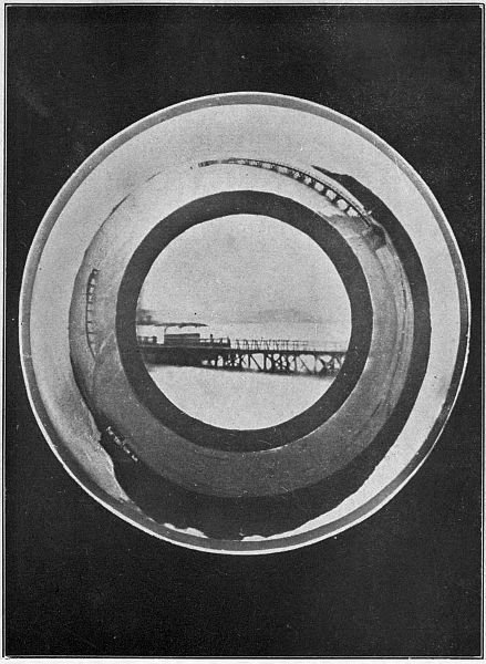
All recently built submarines have two periscopes, one of which leads into the conning tower and the other one runs down into the navigating room. Hence if one or the other is put out of commission by shell-fire, or otherwise, the submarine can still see and find its way about.
Gauging the Distance of an Enemy Ship.—An instrument called a telemeter (pronounced te-lem´-e-ter) is attached to the periscope near the eye-piece, and the observer can by looking into it measure the distance away of an enemy ship. This is done from the size of the image it makes on the eye-piece.
Without this instrument the whole submarine, as large, as wonderful, and as costly as it is, would be of small value, for by it the captain is able to set his torpedo director very accurately and hence to aim the torpedo so that it will make a sure hit.
The Latest Type of Periscope.—As the periscope just described, and which is still in use on submarines, has a very limited field of vision at any given setting—that is to say, only about ⅙ th of the horizon can be seen when the instrument is pointed one way—and as a periscope which would show the whole horizon[137] at the same time was badly needed, a British firm of opticians set out to invent one.
The hardest part of the task was not to get a complete view of the whole horizon at the same time but to prevent the rays of light which form the images from getting mixed up with one another, or interfering, and so producing a blurred and indistinct picture.
The new complete-view periscope differs from the older style only in having a circular lens and prism; these gather in the light, bend the rays and project them on down through the telescope lens until they reach the lower prism when all of the images are reflected into the eye-piece where the observer sees it as a circular picture.
This new improved form of periscope is of great value, for it gives a safety-first view on all sides of the submarine at the same time and the observer does not need to keep turning the eye-piece, and this is of great value when a submarine is being closed in on by two or more enemy ships.
It is a well-known fact that a large number of submarine accidents have been caused by the limited range of view offered by the old-style periscope, and in some cases the undersea craft has been rammed or sunk by gun-fire from an enemy ship which she did not see.
The new periscope makes it impossible for a destroyer to creep up on the submarine without being caught in the act. Nearly all of the undersea craft now being turned out by all of the warring nations[138] are fitted with the new 360-degree[27] vision periscope.
The Limited Use of the Periscope.—Notwithstanding all these latest improvements in the periscope, its use is quite limited, for it can be used only when the submarine is running awash or partly submerged, and since the tube of the instrument is only 20 feet high the distance to which a ship can be seen is about five miles.
When running partly submerged the tube of the periscope sticks up and out of the water about 10 feet, when the distance range of vision is then cut down to about two miles, for the curvature of the earth’s surface meets the line of sight and everything that is at a greater distance than this from the submarine is below the horizon and hence invisible.
Should an enemy destroyer get within firing range of the submarine and the captain of the latter craft wants to watch it, only the hood of the periscope is poked up above the water; but of course the distance range is again cut down.
The captain of a submarine has to contend with all these adverse features of the periscope even on bright, clear days and when the sea is calm; on dark and foggy days, when a heavy sea is running, the periscope is next to useless, for the mist and spray gather on the objective lenses and this makes it next to impossible to see anything.
Worst of all are the waves which break over the periscope, and this prevents a ship from being seen even if it is only a little way off. It is in rough weather that a submarine takes the longest chances; but to put behind him any danger that may be lurking hard by, the captain prefers to run undersea and come to the surface only when he has to.
A scheme to clear the moisture from the objective lenses is a device called a sprayer. It is made and worked so that an observer at the periscope can spray the lenses with alcohol. As water has a very great liking—or affinity, as it is called—for alcohol, and as alcohol evaporates almost instantly it carries the particles of water off with it, and this helps to make the seeing better.
The New Enemy of the Submarine.—A new enemy of the submarine has recently made its appearance—an enemy that will make it use a periscope of a new order.
This latest submarine destroyer is the airplane; and as the captain cannot now see directly overhead except when his boat is running light or awash, and the pilot of an airplane can see the submarine when it is submerged to a very considerable depth, it is easy for him to follow the undersea craft until she comes to the surface and then drop a bomb on her.
A story of a running fight between an airplane and a submarine would have put it in Col. Roosevelt’s Ananias Club a few years ago, but to-day it has all[140] come to pass, and it looks now as if a good way to break the backbone of Germany’s ruthless warfare on the sea is to destroy the U-boats with a fleet of airplanes.
Since a submarine has an eye to see with, it is both proper and fitting that it should have a tongue so that it may speak and ears so that it may hear. In fact, an undersea boat is almost human.
The early submarine, though, was not only as blind as a cave fish, but it was as deaf and as dumb as a snail; and since this was the case, it had to do whatever talking was necessary by means of a deaf and dumb alphabet, that is, by signaling with flags, or wigwagging, as it is called.
The Tongue and Ears of a Submarine.—The tongue of a submarine—or rather tongues, for it has several—is the fanciful name I have given to the means, methods, and schemes by which messages are sent from one submarine to another submarine or to shore, and the ears are the devices by which it receives messages from other submarines and from shore stations.
There are two conditions under which messages must be sent from and received by a submarine, and these are (1) when she is running light or awash, and (2) when she is running submerged.
Now, most of the signaling systems can be used only when the submarine is on the surface, and a couple of them can be used only when she is under water.
Then, again, some systems are good only for daylight signaling, and others for night signaling; others will cover very short distances, but there are systems that will send and receive over long distances. But whatever the system may be there will be found some weak point in it as far as the submarine is concerned.
Kinds of Signaling Systems.—Since no one signaling system will meet the rigid requirements of the submarine, several systems are used. When the craft is on the surface, these are: (1) the flag, or wigwag, system; (2) the flashlight system; and (3) the wireless telegraph system. When the submarine is under water the signaling systems used are: (1) the bell, or violin, system; and (2) the electric current system—all of these will be described in order and as we go along.
The Wigwag Way of Signaling.—The oldest way of sending messages at sea is by wigwagging, that is, using flags, and this system is still in use in the navies of all nations for close range daylight communication.
The way wigwagging is done is like this: Each craft has a signal book which gives the positions of the flags and the meaning of them. These flags are usually manipulated by a signalman (see Fig. 55) though sometimes a mechanical apparatus called a semaphore, which has two movable arms to hold the flags, is used.
Two flags are used, one in each hand or on each arm, and each position of the flags means a letter of the alphabet, and so by showing the flags in various positions to represent different letters words are spelled out.
Another scheme that is used to signal with flags is by running, that is displaying, a number of different colored flags on a halyard. The combinations of flags—or to use the right word, permutation, which[146] means the number of different arrangements of a few flags that are possible—are numerous and each permutation represents some word or a sea-term.
Now, you might think that it would take a couple of hundred flags of different colors to represent a message, and, further, that since there are only eight colors which can be told from each other at a distance of half a mile, signaling by colors could not be done.
But this is what you think, and not what you have figured out, for if you have eight flags of different colors and display them, four at a time, on the signal halyard you can make the surprising number of 1680 permutations; and this, you will allow, is enough to say anything that you may have to say.
Although a code book is found in every signalman’s outfit, he is a chap who knows all the signals by heart and can send and receive flag messages almost as fast as you can write down the words.
The Flashlight System.—There are two methods used for sending signals at night over short distances, and both are done by means of light; named, these are (1) the colored light system, and (2) the searchlight system.
The Colored Light System.—In this system incandescent electric lights of high candle power are placed back of bull’s-eyes, or lenses, made of colored glass, and these lights can be switched on and off and so form combinations that spell out words just as the colored flags do. This system is very much used for short range signaling at night.
The Searchlight System.—A searchlight, that is an electric arc light set in front of a silvered reflector, can be seen for long distances, and so it, too, is largely used for night signaling.
The searchlight, which can be turned in any direction, has a movable shutter, or metal disk in front of it, fixed to a handle, and when this is worked up and down like a telegraph key, the shutter cuts the light off and lets it shine forth accordingly.
By working the key, and hence the shutter, the light is broken up into dots and dashes of the regular Morse telegraph alphabet, and these short and long flashes are read by the operator on the other boat.
The Wireless Telegraph System.—The wireless telegraph has all the other systems of signaling, when the submarine is afloat, beaten by miles.
Among its advantages are (1) it can be used in the daytime as well as at night; (2) the electric waves it sends out cannot be seen and this makes it harder for an enemy ship to locate the boat it is on, and (3) its signaling range is not cut off by the curvature of the earth.
The Parts of a Wireless System.—There are three chief parts to every wireless telegraph system, and these are (1) the sending apparatus, or transmitter, as it is called; (2) the receiving apparatus, or receptor, as some “high-brow” has named it; and (3) the aerial wire, which is used for both sending and receiving.
The sending apparatus is made up of (a) a source
of current, which on a submarine is the storage battery;[148]
[149]
(b) an induction coil; (c) a telegraph key; (d) a
tuning coil; and (e) a condenser.
The receiving apparatus is formed of (a) a tuning coil; (b) a condenser; (c) a detector; and (d) a pair of head telephone receivers. A wireless telegraph set is shown in Fig. 56, A and B.
Both the sending and the receiving apparatus can be connected with the aerial wire by means of what is called a throw-over switch, the purpose of which is to connect the aerial to the transmitter when messages are to be sent out and to connect the aerial to the receiver when messages are to be received. Thus only one aerial is needed.
How Wireless Works[28]—When a wireless message is sent the operator makes and breaks up the current from the storage battery into dots and dashes by means of the telegraph key.
This interrupted low pressure current flows through the induction coil and this changes it into a high pressure current which makes a jump spark. The spark in turn changes the high pressure current into high frequency currents, or electric oscillations, as they are called; and as these run forth and back over the aerial wire they set up waves in the ether which are called electric waves.
These electric waves are exactly like light waves, but they are so long that the eye cannot see them. The[150] tuning coil and the condenser are used to give the waves whatever length the government says they must have.
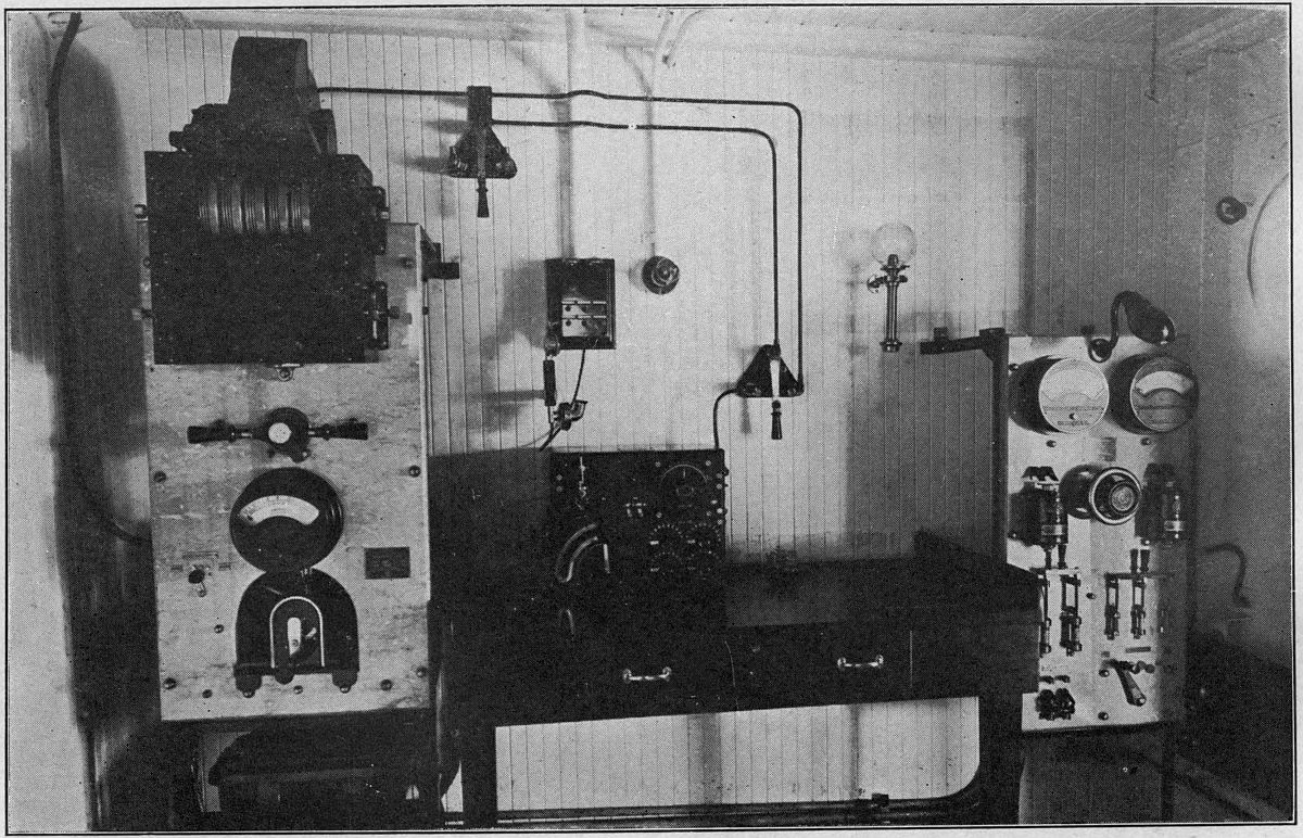
When the electric waves that are sent out by the aerial of the transmitting station strike the aerial which is connected with the receiving apparatus of another ship and the operator is listening in, the waves are changed back again into high frequency currents, and these run to and fro on the aerial wire and up and down through the tuning coil, the condenser and the detector.
The latter instrument changes the high frequency currents, which are alternating, into an interrupted direct current; and these in turn energize the telephone receiver, with the result that the dots and dashes sent out by the sending operator are reproduced by the telephone receiver, when they are heard by the receiving operator who is listening in.
The tuning coil and condenser enable the operator to tune his receiving apparatus to the length of wave which the transmitting station is sending out, and this operation is called tuning in.
The wireless station of a submarine is usually located in the navigation compartment. Although the aerial is neither high nor long, messages can be sent to upwards of two hundred miles and received over much greater distances.
Wireless allows the submarine not only to keep in touch with its base but also to pick up and intercept messages from enemy ships, and though the operator[151] may not be able to decipher them it is possible for him to determine in about what direction and at about what distance the ship is.
Another use to which wireless is put is signaling between submarines that are doing patrol duty at the same time but which are too far away from each other to use either flags or lights.
Wireless telegraphy cannot, however, be used when the submarine is under water, for water absorbs the electric waves in exactly the same way that it absorbs light waves. But taken all in all, wireless is by far the most important of all the signaling systems yet invented, and it is the only one by which messages can be sent and received by either day or night, over long distances and in any kind of weather.
Underwater Signaling Systems.—As I have said before, there are two kinds of signaling systems used by a submarine when it is under water.
While both systems leave much to be desired—for neither can begin to come up to wireless, either in ease of operation or in signaling range—as they are the only known means by which underwater communication is possible, there is nothing to do but to use them.
The Bell or Violin System.—This is a signaling system that is widely used on ocean going vessels of all kinds to send out warning signals in thick weather.
It is a system in which a large bell or other vibrating apparatus sets up sound waves which travel in every direction through the water; when these waves[152] reach another craft they are heard by means of a telephone receiving apparatus.
Now, water will carry sound about ten times as far and four times as fast as air; that is to say, if a bell is struck a blow in air and the sound waves it sends forth can be heard a distance of half a mile, then the same bell if it is struck when it is submerged in water will send out waves to a distance of five miles.
The sending apparatus consists of either a bell (see Fig. 57), the striking mechanism of which is worked by electricity, or of a large saw-toothed wheel which revolves rapidly against a tight wire and in consequence sets up a musical note. This latter kind is called a violin transmitter.
Whichever is used is lowered through a hatch in the hull of the submarine, and the bell is rung or the wheel is rotated by an electro-mechanism, which sends out sound waves to distances of from 5 to 15 miles.[153]
The receiving apparatus (shown in Fig. 57) is formed of an ordinary telephone transmitter, and this is fixed in a small iron tank filled with water and bolted to the inside of the skin of the hull. There is one of these transmitters on each side of the ship, and each one is connected with a battery and a pair of head telephone receivers placed in the navigating compartment.
When the bell or violin of another submarine, or the base ship, sends out its message in the Morse alphabet the sound waves, as you will see by looking at Fig. 58, travel through the water and strike the hull of the ship, go through its skin, set the water to vibrating in the tank, and this, acting on the telephone transmitter, makes it vary the electric current of the battery; the varying current flowing through the telephone receivers reproduces the distant sound of the bell or the violin[154] wheel, and the operator on the submarine hears it.
The receiving apparatus also serves to detect the presence of an enemy ship when it comes within torpedoing range by the sound waves set up by and by which are sent out through the water by the rapid turning of the ship’s propellers.
The Electric Current, or Conductivity, System.—In this submarine telegraph system the water, which is a fairly good conductor of electricity, is made to carry an ordinary battery current between the sending and the receiving stations.
Since the water conducts the current of electricity, it is easy to see why it is called a conductivity system. It is also called an underwater wireless system, but while it is wireless in the sense that there are no connecting wires between the two stations, you must not confuse it with the real wireless system, which uses electric waves, for in the former the energy decreases[155] as the cube of the distance and in the latter only as the square of the distance.
The Parts of the Conductivity System.—There are three principal parts to this system, and these are (1) the sending apparatus; (2) the receiving apparatus, and (3) the submerged copper plates which conduct the current from the sender into the water and from the water into the receptor.
The sending apparatus consists of (a) a source of direct current, and the storage battery supplies this; (b) a reactance, or kick coil, as it is commonly called; (c) a rotating interruptor, and (d) an ordinary telegraph key.
The receiving apparatus is made up of (a) a telephone induction coil, and (b) a pair of head telephone receivers. All of this is shown in Fig. 59.
One of the submerged copper plates is fixed to the bow of the submarine’s hull, and the other is secured to the stern, in order to get the plates as far apart as possible. These plates are connected to a throw-over switch, so that either the sender or the receptor can be connected to the plates as the operator wishes.
How the System Works.—The instruments of the sending apparatus are connected up as shown in Fig. 59. Now when a message is to be sent from one submarine to another, the operator sets the rotary interruptor, which is run by an electric motor, to spinning, and this makes and breaks the current several hundred times a minute as long as he holds the key down which closes the circuit.
The result is that each dot and dash he makes is formed of a large number of separate currents, and as these flow through the reactance coil, it gives each one a little kick and sends it out into the water through the copper plates; the currents then spread out between and from the plates in closed lines which extend to very considerable distances, as shown in Fig. 59.
When these electric currents reach the plates of the receiving apparatus on the submarine where the operator is listening in, they flow up the wires and through the primary winding of the telephone induction coil; these broken up direct currents flowing through the primary coil set up alternating currents in the secondary coil and also raise the low pressure currents into high pressure currents—that is, currents of a higher voltage, as it is called.
These alternating high pressure currents then flow through the telephone receiver, and by varying the strength of the magnet of the latter the dots and dashes of the sending station are reproduced and the receiving operator hears them as a musical buzz.
You will remember, back there in the first chapter, we told you about Fulton’s submarine and how one man operated it, so naturally he was his own superior officer and able-bodied seaman both rolled into one.
Since those early days of underwater navigation wonderful advances have been made, not only in submarine construction, but in the crew that mans her as well, for not only are there many men in the crew of a submarine of to-day, but each man is highly trained for the work he has to do.
At the present time the personnel, which means the force of men employed as well as their fighting qualities taken as a whole, includes a list of no less than 48 officers and seamen, and each and every one of them is a picked man. The smaller submarines, of course, carry a smaller complement of men, for there is neither as much work to be done nor is there room to bunk them.
Conditions on Early Submarine Craft.—What with the great array of instruments, apparatus, and machines that must form the equipment of the submarine to make her an efficient fighting unit, there is but[160] little space left in her for her crew, and this was especially so in the early days.
Owing to the fact that space was, and still is, at a premium, the crew of a submarine does not list a man who has not one or more important parts to play in the actual operation of the boat; for every addition to the crew means that much less comfort for each one, and interferes moreover, with the carrying out of orders in a rapid and effective manner.
When Crews Were Hard to Sign.—There were no conveniences provided on the first submarines for their crews; indeed, as we look back now on those pioneer attempts, it seems verily as if no thought at all was given to the health and safety of the men who manned them.
It was enough, albeit, to get a boat that could be submerged and which stood a fair chance of coming to the surface again; so of course there was not enough air, and the little there was was bad; the quarters, if there were any at all, were very small and close, and there was a deal of danger attending the most ordinary maneuvers.
Now, the able-bodied seaman knew all these things only too well, and, what was more, he had heard tall yarns spun around of the terrors of the new and strange craft, and these did not tend to strengthen his desires to hurry up and enlist in that arm of the naval service.
When the various governments began to take a real interest in the submarine and to keep up an active[161] flotilla, they began to realize that unless the comfort and the safety of the men were looked after better than they had been in the past the submarine service would soon be shorthanded and badly crippled.
So as a sop for the bad conditions which the crew must stand, the men were offered a large bonus—that is, extra money besides the regular pay—and also extra privileges. In truth, the offers were so generous and alluring that it was not long before seafaring men began to rush to the call, and from that time to this there has never been the least trouble in getting crews for undersea fighting craft.
As the construction of the submarine moved on apace and it grew in size, and as new inventions and improvements were made to supply pure air and enough of it, all the discomforts vanished, until a berth on an undersea craft is as agreeable, nearly, as it is on a man-o’-war.
What the Base-Ship Is For.—While, of course, the chief object of a submarine is, as you can tell by its very name, to travel undersea when needs be, it is, as you have already learned, not fitted to run for more than forty-eight hours at a stretch when totally submerged, and as a matter of fact it spends most of its time afloat and in the awash condition.
From this you will see that living on a submarine is for the greater part of the time just about the same—though a little more confined—as it is aboard any other craft. Her actual cruising radius—that is the distance she can sail from her base of supplies—is seldom[162] more than 2,500 miles; and she is limited to this mileage simply because of the lack of storage for the food and fuel she needs.
For this reason every submarine must have a supply base, and this usually is a ship which is supplied with the necessities of life and power. The base-ship, as it is called, is also a floating dock,[29] has a complete machine shop, and every other conceivable thing that she needs to take care of her flotilla of submarine children. A mother ship is shown in Fig. 60.
The base-ship follows after her submarines, not directly on their heels, but so that they will be within easy cruising distance of her. It may seem that 2,500 miles—nearly the span of the Atlantic—is a long distance, and it is for a submarine to make one continuous trip; but ten short runs of 250 miles each will use up her supplies and then she will have to return to her base for more.
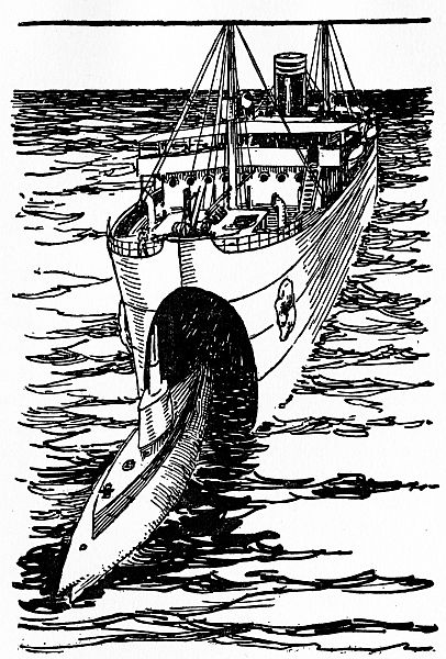
In times of peace a submarine never strays far from
her base-ship, indeed, she spends most of her time
laying alongside of her except when at practice. At
such times the submarine and the base-ships are considered[163]
[164]
integral[30] parts of each other, and under these
conditions most of the crew stay aboard the ship.
Thus it is that a submarine sailor’s life is nearly all spent above water, and it is not such an unhappy one at that.
How Men Are Trained for Submarine Duty.—The base-ship is also used as a training ship for rookies—that is green hands—and on it they are let into the secrets and mysteries of the working, sailing, and fighting machinery of the submarine.
The rookies are taken in hand by the officers and the more highly skilled sailors of the submarine and drilled in whatever they are to do until it becomes second nature to them, for a fluke of any kind might spell disaster for the whole crew and craft.
The Complement of a Submarine.—The word complement (notice that it is spelled with an e instead of an i) means not some pretty bit of flattery but the full number of men that is needed to man the boat.
The complement of a submarine is not very different from that of a torpedo boat or other small naval craft. There is, first of all, the commander, or commanding officer, who is in charge of and is responsible for the crew and his boat.
His word is law and he is as able a navigator and tactician—as an expert in directing a submarine, with skill and shrewdness is called—as it is possible to get. His brain is the master brain of the mighty craft, for[165] it is he who plans what his crew must do, and when they must do it to the end that the enemy ship shall be sunk.
Then there are the officers under him—lieutenants (pronounced lef-ten´-ants, with the accent on the second syllable, by stage folks in naval plays)—and these correspond to the first and second mates, etc., of a sailing ship.
These officers are also thoroughly competent navigators, and should anything happen to their superior officer, any one of them could take command of the submarine and give a good account of himself.
The rest of the crew is made up of engineers and oilers, torpedo-men and gunners, wireless and signalmen, cooks and able-bodied seamen. The engineers not only must know how to run the engines to get the most power with the least fuel, but they must be machinists of the highest class in order to make repairs of every kind should the boat be damaged by shell fire.
The torpedo-crew, as the men who have charge of the torpedoes are called, take care of these mighty missiles from the time they are lowered into the hull from the base-ship to the moment they are shot from the tubes on their courses to sink the enemy ships.
This crew also takes care of the trimming tanks, which must, as we have explained before, be filled with water to offset the effect of lightening the submarine by the sudden discharge of the torpedoes. The gunners, of course, look after the guns and are expert[166] gun pointers. All of the new submarines are equipped with wireless and this is worked by two or more experienced wireless men who are on constant duty while the boat is afloat and who operate the conductivity telegraph system when the craft is running submerged.
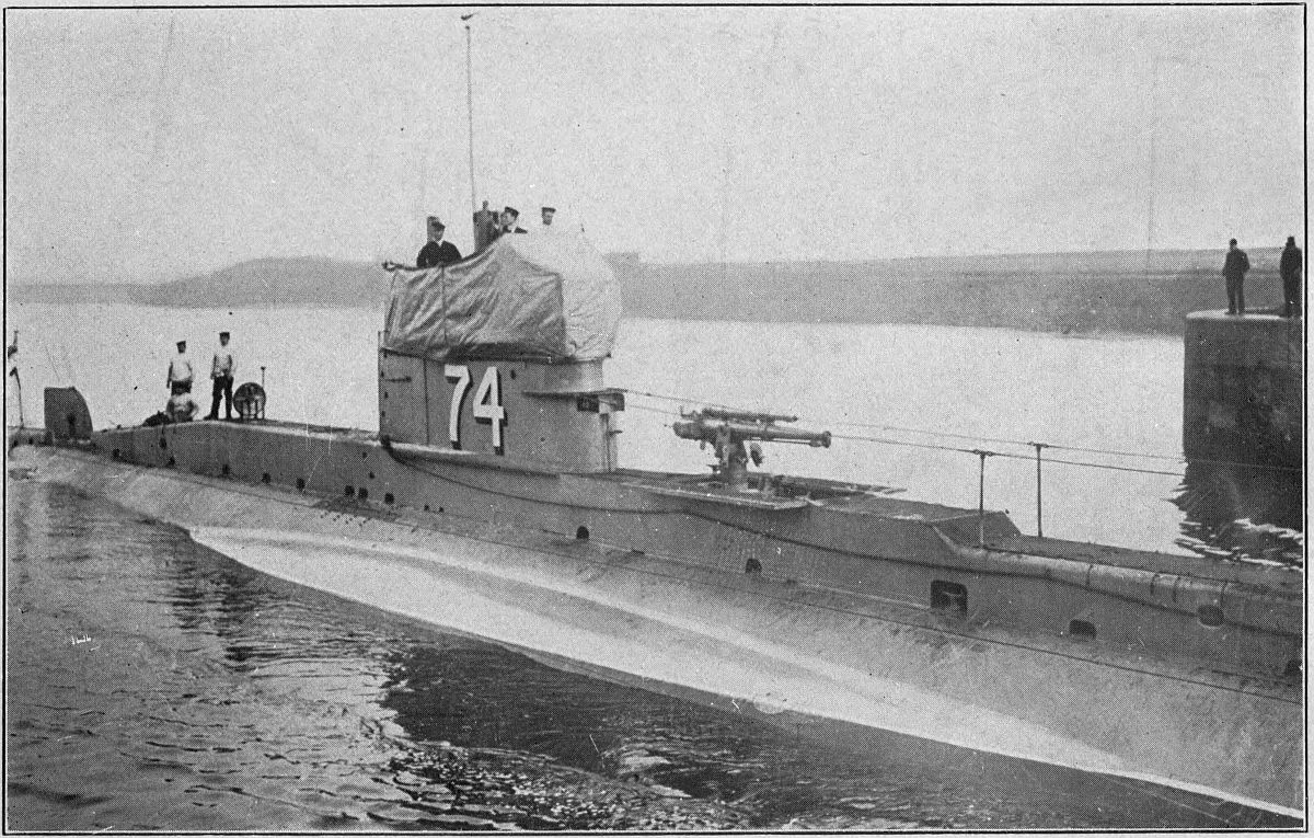
The submarine is kept in constant touch with the mother ship, as the base-ship is sometimes called, and as the latter has a much more powerful sending apparatus it can, in turn, communicate with the land either directly or by relaying the message by another ship.
The wireless operators also keep busy listening for the first faint signals sent out by enemy ships which may come within range of their instruments, and though they will not be able to read the messages if they are sent in cipher code[31] they can at least know of the proximity of the ship.
Breaking in Raw Recruits.—When there is peace on earth and good will toward men the submarine never gets very far away from its base-ship, about its only excursions being for drill and practice, which is made up of maneuvering the submarine and torpedo practice.
To maneuver the craft means to make adroit moves and changes of position, that is, the boat is put from the afloat into the awash, submerged, and totally[167] submerged conditions by and for the benefit of both the new men and old hands.
The submarine’s place at sea—that is, her longitude and latitude—is found solely by log distances and compass courses while the boat is running submerged, and her course is corrected for drift and leeway; navigating the submarine by these means is called dead reckoning.
Torpedo practice consists of firing torpedoes with dummy heads, that is, heads which do not contain a charge of explosive, at floating targets which the submarine or a lighter tows out to sea and anchors fast. Whether the torpedoes hit or miss they come to the surface after having been shot and are picked up again and returned to the submarine.
By constant practice the men of the torpedo-crew become highly skilled in hitting the target with the cigar-shaped projectile, and they are not allowed to get rusty for want of constant practice.
To add to the knowledge which actual practice gives the raw recruits, as well as the more experienced men, the officers lecture to them on every subject that has to do with the design, construction, and operation of every working part of the submarine.
In this way the crew is trained to do their several individual duties with clock-like precision and is fit and ready at a moment’s notice to handle the craft for all she is worth when war comes.
The Conditions in War Time.—When the dove of peace has had its tail-feathers plucked out by the[168] god of war and the enemy nations are arrayed in battle formation against each other, then the submarine and her crew are welded into a destroying unit of the most treacherous and dangerous kind that the sea has ever known.
The conditions on board a submarine are quite different in war time from those when the nations are at peace. In the first place, when submarine chasers and aircraft are scouting the seas in search of underwater boats it is not only dangerous but often impossible for a submarine to keep in touch with the base-ship by wireless.
We say dangerous because wireless messages flashed forth and back would betray its presence to an enemy ship, and we say impossible in virtue of the fact that the craft often has to run under water for as long a time as she can stay down.
When cruising on the surface the sharpest lookout must be kept every moment of the time for an enemy ship, which may be torpedoed if it is a merchant vessel, or the submarine must dive and get away from it, if it should be a chaser or other kind of armed and armored boat that is looking to sink her.
Under these strenuous conditions the crew is keyed up to the highest pitch and the severest discipline is maintained on board. Torpedoing, diving, submerging, and all the other drills that have been learned under the easy routine of make-believe war now become stern realities upon which the very safety of the submarine depends and hence the lives of the crew.
When the naval powers were waking up to the fact that the submarine was worthy of some consideration, undersea tactics was a thing that was yet to be invented.
These early craft had a very short range of travel and because of their poor construction and lack of power they were not at all adapted for ocean-going, hence they could not accompany the fleet of warships on their maneuvers.
They were, however, thought very well of for coast patrols, and this was the duty given them to perform; each submarine had a stretch of coast which it was to watch and tactics and maneuvering were not needed for this service. Even when it was expected an attack might be made, the only thing that was required of them was to be on the lookout, signal the forts on shore, dive and get out of harm’s way.
But as the size, range, and speed of the submarine was increased she gradually took her place along with the auxiliary[32] craft of the fleet, or squadron,[33][172] and began to take part in the maneuvers with it. It was then that certain fixed duties were assigned to her, and her relation to the other boats became more clearly defined and definitely fixed.
As late as the Spanish-American War, and that was only a score of years ago, the submarine played but a sorry part. A few years later, however, when the Russo-Japanese War was fought, the underwater fighting craft showed for the first time in the game of naval warfare the kind of stuff it was made of.
In the years of peace and prosperity that passed between the end of the Russo-Japanese War and the beginning of the great world war of the nations that is now going on, the submarine was experimented with and improved upon until it has thrown all the other types of naval craft, from the dreadnaughts on down into the shade where there isn’t any shade.
The result of it all is, as you probably know, that the submarine has developed a kind of warfare all its own and which it carries on entirely without help. Imagine, if you can, that in the greatest war that has ever been waged giant battleships are sewed up in the harbors of the enemy while her submarine flotillas are everywhere at sea and carrying on a most effective blockade! Such is the rise of the submarine.
The Uses of the Submarine.—There are two chief uses to which the submarine is put, and these are (1) as a reserve defense or offense for the fleet, and (2)[173] as an offensive weapon for the purpose of maintaining a blockade.
How She Works with the Fleet.—In the first instance, that is, where the submarine is used as a means of defense and of offense with a fleet or squadron, her tactics are well defined and clear-cut.
Her activities under these conditions are rather limited, for she is not built speedy enough to keep up with a swiftly steaming fleet. This, then, in the very nature of things, keeps the submarine from playing an otherwise all-important rôle of scout-ship.
Further, this lack of speed on her part prevents her from engaging in battle as an actual part of the fleet or squadron, for very often it is the speed of the attacking men-of-war that makes for victory, and a flotilla of submarines that lagged behind would prove more of a hindrance than an aid.
But what the submarine can and does do to great advantage is to attack an enemy fleet either as a defensive or an offensive measure, depending on the relative strengths of the fleets which oppose each other.
The Submarine Flotilla as a Means of Defense.—Now let us see first what happens when a fleet with a flotilla of submarines attacks another fleet which is without them.
If the attacking fleet is the weakest—that is, its guns are the lightest—then the submarine flotilla will take a defensive stand, though the opposing fleet is making the attack. The submarines will lay off to the rear of the attacking fleet, and then if the gun-fire from the[174] enemy waxes so warm that the attacking fleet is forced to retire the submarines are in a good position to aid the fleet in its retreat, as shown in Fig. 61.
Now, as soon as the pursuing ships come within range, the submarines let go their torpedoes at them and these either blow them up, cripple them, or scare them off. In a maneuver of this kind the commander of the fleet executes his retreat in such a way that the heavier-armed pursuing fleet must pass near his submarines, which are usually submerged and are therefore invisible.
The Submarine Flotilla as a Means of Offense.—If, now, the attacking fleet is stronger than the defensive fleet, then the submarines of the attacking fleet will also take an offensive part. In this case the submarines will take up a position to the rear of the defensive fleet.[175]
The commander of the attacking fleet will then use such force on the enemy fleet that it will retreat along the path where the submarines lay, when they will, of course, torpedo them, as shown in Fig. 62.
Both these methods of attack have been used with signal success in the war that is now going on.
The Submarine as a Scout.—Although the submarine is useless as a scout for a swiftly moving fleet still it can render great service as a scout on its own hook.
By way of illustration let us suppose that the enemy has a harbor that is well protected by forts and guns, that her fleet is laying to in it, that we want to know how many ships the fleet is made up of, and, finally, what class of ships they belong to.
It is the duty then of a submarine to get into the harbor and take a general survey of the situation.[176] You may wonder how the craft is to do this, since the harbor is mined; but by skilful handling, the captain will usually get through safely, find out all that he wants to know and run out again.
Besides thoroughly reconnoitering a harbor, the submarine can lay a few contact mines, as we explained in a chapter that has gone before, in positions of which the enemy fleet is in entire ignorance and which will be more than likely to result in the destruction of at least a part of the fleet.
Further, the submarine is used to destroy fields of mines which have been laid by the enemy in a harbor. This is done by mines thrown from the torpedo tubes among those that have been planted and which explode by the concussion.
The Submarine as a Blockader.—The most important use to which the submarine has ever been put and one that was never thought of seriously until the present conflict is that of a blockader.
Ever since the beginning of this war Germany has realized the tremendous need of keeping the neutral[34] countries from supplying the Allies with munitions and food supplies, and she has prepared for years a blockade of a new and very effective kind, and this is by destroying merchantmen by submarines.
England and the other Allies have done the same thing with the Central Powers—which is not a very hard thing to do because Germany’s fleet of warships[177] is cooped up in her various ports and dare not venture forth, and so the task is left entirely to her submarine flotilla.
And what makes it still harder for the German submarines is that the Allies keep on the constant watch for these enemy undersea craft, and this they do with their submarine destroyers, and the United States is after them with her submarine chasers, to say nothing of England’s aircraft attacks.
Altogether it is very hard for the enemy submarines to keep in touch with their respective bases or to receive orders as to their courses of action. When on blockade duty, then, the captain of a submarine is in very truth, the commander of his craft and it is strictly up to him to determine what her tactics shall be.
As long as he does his work well, which means that he sinks a fair number of all the ships that enter his zone, his superior officer, wherever he is, will have no quarrel with him as to when or how he does the work.
So you see the tactics used by the captain of a submarine while doing this kind of work depend entirely on the conditions he encounters at the moment, and on the quick decision and judgment of the captain depends the success or failure of the attack.
How a Submarine Attacks a Merchantman.—As a general thing submarines travel alone when merchantmen are to be torpedoed.
The sea is mapped out into zones, as certain areas or parts of the sea are called, and each zone, or part, is[178] usually assigned to a single craft; the submarine patrols this zone constantly, and the captain and his officers keep their weather eye open for passing merchantmen or vessels which might in any way aid or carry supplies to the enemy.
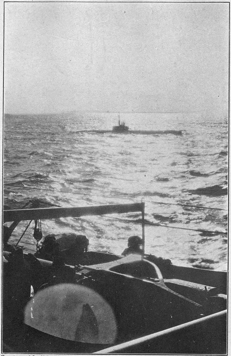
To do this the captain of the submarine stops every ship that comes his way and has her papers and cargo examined, and in this way finds out whether the ship is what she seems to be or if she carries contraband—that is arms, ammunition, and war supplies of any kind—or not.
The way in which this interesting procedure is done is as follows:
The submarine, let us say, has sighted a ship, and seeing that it is to all intents an unarmed merchantman she rises to the surface and trains her rapid-fire guns on the craft. Next she signals the ship to stand by and at the same time she runs toward her.
Now the captain of the ship has three courses open to him: (1) to put on full speed and try to get away, trusting to luck to prevent his craft from being shot full of holes or torpedoed; (2) to take a still greater chance and try to ram the submarine with the sharp, steel-shod bow of his ship and so either disable or sink her, and (3) to comply gracefully to the request and heave to.
If the latter is done, the collapsible boat of the submarine is rigged up and a couple of the officers and crew row over to the ship, when they are hauled aboard and go through her. Should they find nothing of a[179] suspicious or contraband nature, the boat returns to the submarine and the ship is allowed to go her way.
But, on the other hand, if contraband is found on board, the captain of the submarine will do one of these two things: (1) he will warn the crew of the enemy ship that he is either going to open fire on her with his guns or torpedo her, and to take to the life-boats, or (2) he will sink her without warning if the whim so seizes him. Often the captain of the destroyed craft is taken aboard the submarine and held as a hostage.
When Submarines Attack in Pairs.—Another strategic scheme that is used to torpedo enemy craft is to work submarines in pairs.
This is not done, as a rule, except where the ships may, in virtue of their armament, prove dangerous to a single submarine and then they are sunk without warning.
Tactics of two different kinds are used in the actual stopping of the craft. The first is for the submarines to lay off from each other at a distance of from three to five miles (as shown at A in Fig. 63). Then when the submarine, with her periscope above water, spots an enemy ship, she signals to the other submarine, which is submerged, and gives her the exact speed and course of the armed vessel.
The submarine with her periscope above water cannot be seen by the ship because she is too far off, and the nearby submarine cannot be seen because she is totally submerged; so the first submarine directs the second[180] submarine how to train her torpedo tubes on the enemy ship and when to shoot the torpedoes at her. By these tactics a ship can be sunk without either of the submarines being seen.
The other and second way by which an armed ship can be attacked is by having a pair of submarines travel together, one directly over and separated from the other by a distance of only twenty or thirty feet (as shown in Fig. 63).
Now, when a ship is sighted by the craft nearest the surface she comes up boldly and demands the hostile vessel to heave to. Should, instead, the enemy ship open fire and cripple or destroy the submarine, the submerged submarine takes up the fight and shoots a couple of torpedoes at the aggressive ship and so puts an end to her, if possible.
The tactics we have told you about are only a couple[181] of the many used by present-day submarines; we should like to go on and write a book about them but if we did we’re afraid the Imperial German Government might not like it, so we’ll stop here.
It is the boast of Germany that she will win the present war by sinking not only all of the ships of the Allies, but those of any other country which may trade with them.
Now, the United States demands the freedom of the seas for every American citizen and for every ship that flies the stars and stripes and to make good this demand is what brought us into the war.
If Germany could destroy all of the merchantmen of the Allies—and we are now one of them—as she wants to do, she would doubtless be the victor. She hopes to but will never be. The blockade by her submarines is growing more and more serious and many plans and schemes have been put forth to outwit, offset, or to break it down by destroying her destroyers.
There are at the present time[35] only about thirty million tons of shipping[36] in the world which can be used to supply the Allies of Europe with munitions of war. The German U-boats are picking off ships, both neutral and otherwise at the rate of half a million tons a month, and at this rate of destruction shipping cannot[186] last more than a few years. Hence the great need of breaking the blockade and of doing it quickly.
Schemes for Outwitting the Submarine.—Many plans have been thought of and tried out to get the best of the tough old submarine and so defeat it; and among these are:
(1) To build ships that are so heavily armored that they can withstand the attack of torpedoes.
(2) To build ships which have a light enough draft and are speedy enough to outdodge and to outrun the swift torpedo.
(3) To outrig the ships below the water-line with nets which prevent the torpedoes from striking the hulls hard enough to explode them.
(4) To fit the ships with wireless ears which will detect the presence and determine the position of the submarine before it gets within torpedoing range and so give them a chance to escape.
(5) Any number of other impracticable schemes.
Now, you may ask why these schemes are useless. Among the reasons are these, (a) steel armor has yet to be made that will withstand the violent explosive power of the torpedo, (b) ships with a draft light enough and a speed great enough to get out of the way of a torpedo could not be used as freighters, (c) nets on ships make them slow and unwieldy, and as soon as they were used the torpedoes were fitted with steel cutters which enabled them to go through as easily as before, (d) the art of wireless has not yet advanced to the point where it is possible[187] for a ship to detect the presence and position of a submerged submarine, (e) every other scheme that has been put to the acid test has had a glaring fault in it.
Plans for Destroying the U-Boats.—Now, the right way to break the German blockade is to destroy the U-boats, and plans along this line have been devised and carried out with better success.
The submarine can be destroyed in several ways. Among the most important are (1) by laying mine-fields; (2) by arming merchantmen with rapid-fire guns; (3) by destroying the base-ships which mother the submarines; (4) by hunting them down with submarine chasers, and (5) by dropping bombs or shelling them from aircraft.
Laying Mine Fields in Harbors.—This plan is very good for protecting harbors against submarine attacks; but as nearly all the merchantmen are sunk from 200 to 300 miles off the coast, the use of mines for the protection of shipping is very limited.
Arming Merchantmen with Guns.—Arming merchantmen has met with some success, but as a matter of fact it is a very uncertain means of protection, and the large number of armed ships which are sunk weekly shows that the plan is weak.
As a merchantman, or freighter, is usually a slow craft, and a submarine can easily out-maneuver it even when the submarine is on the surface, and when she is submerged she cannot be seen, it must be clear that ordinary rapid-fire guns cannot easily hit her.[188]
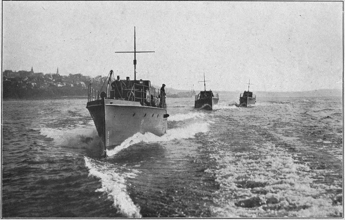
Destroying the Mother Ships.—To destroy the base-ships is, though it may sound like a paradox, one of the best and at the same time one of the least practical plans of getting rid of the submarines that infest a certain zone.
It must be clear if the base-ships are destroyed that the submarines they mother would speedily come to an end. Knowing full well that the Allies would try to find out her bases, both on land and sea, Germany has hidden most of them well, and those that are not hidden are protected by guns of such caliber[37] as to prove a source of danger to even a fleet of first line dreadnaughts.
Since the bases are too hard to find and too hard to destroy when once found, other easier and more practical plans have been devised, tried and found fairly successful.
Kinds of Submarine Chasers.—And now we come to a class of naval craft to which the name submarine chaser has been given, and she has proved to be the best and most practical plan yet worked out to kill off the submarine.
There are two very different kinds of submarine chasers, and these are (1) boats which travel on the surface of the water, and (2) craft which travel through the air. The first kind only, though, is called[189] a submarine chaser, while the second kind may be either a dirigible balloon or a warplane.
The 80-Foot Submarine Chaser.—The submarine chaser is simply a boat whose success as a destroyer depends on four factors, and these are (a) how fast she can go; (b) how light her draft is; (c) how well she is armed, and (d) how fast she can be built.
Two kinds of these chasers have been built, and both have shown their real worth. The first is known as the 80-foot submarine chaser. 550 of these noble craft have already been built for England and sent over to operate against the U-boat in British waters.
They are powered with gasoline engines and are built just about like the high-speed pleasure boats that are now so common here on this side of the Atlantic, that is, they have a three-quarter cruising cabin and cockpit as shown in Fig. 64.
They are very seaworthy, and the powerful gasoline engines installed in them give them speed enough to outrun the fastest submarines that have yet been built. Each one carries a rapid-fire gun of the 3-inch type.
The 110-Foot Submarine Chaser.—The only fault with the 80-footer is that its small size makes it impossible to store away enough fuel to give it a large cruising radius, and so a new type of submarine chaser is being built which is 110 feet long. Its general appearance is shown in Fig. 65.
This boat is powered with steam engines and oil-burning
boilers which drive the chaser at the very fast[190]
[191]
[192]
speed of 25 knots. The craft is armed with a battery
of two 3-inch guns mounted on the fore and aft
decks. The large size of this chaser makes it easy for
it to cruise for long distances, while its speed is 8
knots faster than that of the fleetest submarine and
this makes it a foe that is truly to be feared.
How the Chaser Chases a Submarine.—The way a submarine chaser chases a submarine is like this: each chaser is given a certain area of seaway to patrol. This she does, and if she is lucky she will soon see the periscope of an enemy submarine poking its hood above the water to take a peek around the horizon.
This is the signal for the chaser to bear down on that periscope at full speed, the gunners doing their level best to hit the periscope or any other part of the submarine which shows itself above water.
As it takes time for the submarine to dive or to get her own guns into action, the chaser stands a pretty good chance of either crippling or even sinking her. Further, the submarine cannot use her torpedoes on the chaser, for the latter craft is so short and has such a shallow draft that her hull does not offer much of a target for a torpedo, even though she were standing still, and much less when she is bearing down on the submarine at full speed.
Every once in a while a chaser is able to surprise a submarine when she has come to the surface for a breather and to recharge her storage batteries. When[193] this happens it is simply another case of the cat eating the canary.
If the submarine is within two miles of the chaser she cannot get ready to dive and she must either get her own guns in action or else she must try to outrun the chaser, getting ready to dive as she runs and trusting to the Kaiser that she may not be hit in the meantime.
This last course proves disastrous to the submarine nine times out of ten, and so she usually gets her guns into action and a regular little sea battle is fought right then and there.
Shooting the Guns of the Chaser.—Having found, chased, and caught the submarine, the next thing to do is to put her out of commission. On the guns with which the chaser is armed, and on her gunners, depend to a large extent the success or the failure of the attack.
A gun which had a long range and a flat trajectory[38] was quick in action, and rapid-firing, was thought to be all that a gun should be for submarine execution; and it was all right for shooting at conning towers and similar targets which showed themselves above the water-line, but it was useless for a gun of this kind to try to hit anything that was even a few feet under water.
The reasons for this are somewhat deep and scientific but if you will read carefully, look at the diagrams[194] shown in Figs. 66 and 67, and do a little thinking as you go along you will be able to visualize the whole thing—that is, to see it.
Now, the way this gun was made was to rifle the barrel of it, and this gave a turning motion to the projectile when it was fired, that is, it spun around on its long axis, and the trajectory was flat, which means that the path of the projectile in its flight from the gun to its target was only slightly curved.
Both of these things made the projectile deviate from its course the instant it struck the water, or ricochet (pronounced rik-o-sháy) as it is called; that is, it bounced from the water in exactly the same way that a flat stone skips along when you throw it close to the surface of a pond or lake.[195]
The right kind of gun to use on submarine chasers is not rifled, and the projectile should be given a trajectory, or path, that is much the same as that of an arrow; the result is that a shot can be fired at a submarine which is submerged to a depth of 20 feet or so and be effective because the curve of the path is such that the projectile drops straight, or nearly straight, down on the submarine and penetrates the water as shown in Fig. 67.
Submarine Air Chasers.—Besides the submarine chasers just described, there are two other kinds that have shown great possibilities as destroyers of undersea craft. These are (1) the airship, or dirigible balloon, and (2) the airplane, and it is more than likely that in the near future, should the war keep on, the latter craft alone will be used for submarine chasers.
Where a boat chaser cannot see a submarine at all when she is submerged, an airplane can fly directly over her, follow her every movement, and see her when she is at a considerable depth. (See Fig. 68.)
As the airplane is much more steady in the air than a submarine is on the water and as the former is much quicker and speedier than the latter, a battle between these two very different kinds of craft is an unequal one with the odds greatly in favor of the warplane.
A Way to Lift the U-Boat Blockade.—Here, then, is a real, ready way that the submarine can be destroyed and Germany’s blockade lifted. To put an end quickly and for all time to the U-boat menace,[196] the United States ought to build several thousand airplanes at once and arm these with bombs and rapid-fire guns like the Lewis[39] and send this fleet to patrol the seas.
If this were done there wouldn’t be enough U-boats left in a month’s time to flag a Norwegian fishing trawler. So the thing for your Uncle Sammy to do is to build a great fleet of airplanes, and in the shortest possible time.
There is still another way to break the blockade, and this will be described in the next chapter.
It is less than twenty years agone that the first five baby Hollands were built in this country for, and delivered to, England, and from that time dates the beginning of the art of modern submarine construction.
Since then the size, speed, and cruising radius of each succeeding type of submarine has grown greater and ever greater, until from a craft hardly larger than a power pleasure boat there has been evolved a truly wonderful undersea vessel of magnificent proportions.
Uncle Sam’s Latest Submarines.—The result of this marvelous development is that the latest of Uncle Sam’s submarines are of the 1200 and 1500 tons displacement type and they have a speed of 21 knots on the surface.
These giant submarines have a cruising radius of about 4,000 miles and are fitted with every instrument, device, apparatus and machine that human ingenuity can think of, or at least that has been invented, which goes to make for their operating and fighting qualities and for the safety and comfort of their crews.
From this you will see that since the year of 1900 the size of these craft has been increased about four times, their speed doubled, and their efficiency raised to half again as much. Based on the rapid strides that have been made since the war has been going on, it does not take any great foresight to predict that in the near future, if the U-boat blockade is not broken, submarines of upwards of 500 feet in length and 10,000 tons’ displacement will form the merchant fleet of the United States.
The Great Blockades of the Warring Nations.—The great blockades by which the Allies have bottled up the German Empire by their superior naval forces, and by which Germany is trying to shut off the trading of other countries with the Allies by her U-boat warfare, have prevented either side from scoring a victory.
But with Germany’s usual dogged determination for overcoming the difficulties that beset her, she built a submarine which could travel without a convoy, that is, without any base-ship to go along with her to provision and supply her needs, for 5,000 miles at least.
This giant submarine carried a cargo worth a million dollars or more, sunk out of sight as she left her home port, slipped underneath the grim warships of the Allies which menaced German shipping, and in this way ran the blockade.
Then one fine day there bobbed up in American waters near Chesapeake Bay a monster merchant submarine—the[201] largest underwater craft ever built and the first of her kind ever seen. She was in very truth a nine days’ wonder.
The First of the Merchant Submarines.—The Deutschland, as she was named, was a marvel of engineering skill, and she was hailed as the first of a great fleet of merchant submarines which was to break the Allies’ blockade.
Starting from Bremen, Germany, and traveling underwater through the English Channel for a distance of 90 miles without even once coming to the surface, she made the entire voyage without mishap and docked at Baltimore just 16 days later.
When you think of how carefully she had to be handled and how cautiously she had to proceed so that she might escape destruction at the hands of her surface enemies, you must admit that she made the run in really remarkable time.
Some Facts About the Deutschland.—This great merchant submarine is 315 feet long, 30 feet through the beam, and draws[40] 17 feet of water. She is, therefore, as large as many of our coastwise steamers, so that she is something more than a mere underwater boat—indeed, she is a veritable submarine ship.
Her hull is shaped more nearly like that of a real ship than any submarine craft that was ever built before her, as Fig. 69 shows; but she has a conning tower, periscopes and wireless masts like any of the other of the tribe of submarines.
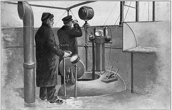
Her wireless aerial is held in place between two steel masts, each of which is 50 feet high and both of which can be folded down on the deck. The mast on her for’ard deck is fitted with a crow’s nest for a lookout, as though she were a real ship.
Her Captain and His Crew.—The inside of her hull is very much like an ordinary merchantman. For’ard are large and comfortable quarters for the officers, of whom there are nine, including Captain Koenig—a man you can’t help but admire. Abaft the ship are the quarters for the crew, and both fore and aft in her hold are compartments for the cargo she carries.
Her Valuable Cargo.—In making her first trip over from Bremen her cargo consisted of dyestuffs, medicines, synthetic stones[41] and other merchandise which took up small storage room and yet which was very valuable.
These she unloaded in Baltimore, and her return cargo was made up of crude rubber, tin, and nickel—materials much needed by the German Government for purposes of warfare.
She also served the very useful purpose of a packet, for by means of her Captain Koenig was able to hand personally to Count von Bernstorff, the German Ambassador to the United States at that time, important instructions which would otherwise have been hard to get through.
Again, what was of even greater urgency was that[204] the Count was able to get rid of certain documents which would have made matters quite uncomfortable for him if they had been found in his possession some months later when the break came between the United States and Germany.
Her Great Engines.—The Deutschland is driven by two 600-horsepower Diesel engines, each of which has four cylinders. She is able to make a speed of 14 knots on the surface, but when submerged her speed is only about half as much.
She is supplied with enough liquid fuel and solid foods to enable her to cruise for 5,000 miles without making port.
Such is the Deutschland, and to her belongs the distinction of being the first underwater merchantman. Under the skilful command of her captain, she served her country nobly and well for the purpose for which she was built.
How the United States Can Break the Blockade.—Right now the United States and the Allies have to face the same gigantic problem that was forced upon Germany at the beginning of the war, and that is to break the enemy’s blockade.
The scheme of keeping the sea-roads clear for shipping by destroying the U-boats has proved a slow and hard process, and so new plans have been mapped out by our naval engineers and others with which to defeat the blockade.
The Wooden Ship Idea.—The first plan, and one which is being carried out with great energy, is the[205] building of hundreds of little wooden ships, each of which is 25 feet shorter than the Deutschland and has a cargo carrying capacity of 3,500 tons, and a speed of 4 knots less than the surface speed of the great German submarine.
The main idea seems to be to turn these little boats out fast enough so that the number the U-boats sink will be so small that the loss will not be felt. The glaring fault of this idea is that while the U-boats are sinking 500,000 tons of shipping a month, American ship-builders can build only 200,000 tons a month, and this is figuring it out with a liberal margin.
While these small wooden craft of the vintage of 1850 would relieve the stress that is now felt in shipping circles they would not by any means remove it.
The Submarine Plan.—Simon Lake, the inventor of the submersible, has enlarged upon the German plan, and his plan is one which our Government ought to carry out, because, in the humble opinion of the writer, it is the only feasible one thus far advanced.
Mr. Lake has organized a company to build a fleet of undersea merchantmen, each boat of which will be ten times as large as the Deutschland and can carry a cargo of 7,500 tons. Mr. Lake says that with the co-operation of the Government he can build 100 of these giant craft in the first year, and that at the end of three years he can have a fleet of 500 of them built and in service. That is to say, in this short time he can have 4,000,000 tons of cargo sailing the seas with absolute safety.
This plan of the great submarine builder is the key which will unlock the horns of our dilemma. The only drawback seems to be the ability of a company to turn out so complex a mechanism as the submarine, and of such an enormous size, fast enough to make up for the rapidly disappearing tonnage of the Allies.
In the meantime the submarine chasers and the wooden and steel ships that are now being built may help to some extent to take care of our shipping until the great commercial submarines of Lake can be built and put into the trans-Atlantic service.
When Submarine Meets Submarine.—When Greek meets Greek then comes the tug of war, so the old saw goes, and it is just as true that the way to break the blockade of the U-boats is to pit the cunning of submarines against them.
With all our shipping going by the undersea route, the U-boats will lose their sting, the blockade will be broken, the power of the Allies will outweigh that of Germany, and the war will speedily come to an end.
And may that time come soon!
THE END
[1] Central Powers: Germany, Austria, and Bulgaria.
[2] Allies: Governments united by a treaty or having common interests. England, France, Belgium, Russia, Italy, the United States, and Japan are called the Allies.
[3] U-Boat: So called because it is an undersea boat, or Unterseeboote, as the Germans call their submarines.
[4] Paleozoic.—The next to the lowest geological series of strata.
[5] The Pterodactyl was one of these and it was the largest living thing that ever flew. It is pronounced Ter-o-dak´-til.
[6] A knot is the speed of a boat when she is making 1 nautical mile in 1 hour. A nautical mile is 6,080 feet.
[7] The design, construction and operation of submarine torpedoes will be found in Chapter V.
[8] The storage battery was invented by Gaston Planté in 1860. The electric motor was discovered in 1876, by whom nobody knows.
[9] These pipes can be bought cut to length and threaded to suit of The Chicago Model Works, 166 West Madison Street, Chicago, Ills., or of Luther H. Wightman, 132 Milk Street, Boston, Mass.
[10] The L. E. Knott Apparatus Company, of Boston, Mass., sell a standard motor, as they call it in their catalogue, for $3.75. It weighs 1½ pounds and takes up a space of about 3½ inches square. Powerful little motors can be bought at almost any electrical supply house, and you can use one of these by building up the base.
[11] Cells of this kind that measure 2 x 2½ x 6 inches on the sides can be bought of the Manhattan Electrical Supply Company, of 17 Park Place, New York City.
[12] A machinist’s saw for sawing metal.
[13] The pulley can be bought of dealers in model makers supplies. See footnote on page 32.
[14] You can certainly get it of the F. W. Devoe and C. T. Raynolds Company, 101 Fulton Street, New York City.
[15] The top of the conning tower is called the bridge.
[16] The hull is the body or shell of a boat or ship.
[17] For a description of the gyroscopic compass, see Inventing for Boys, by the present author and published by the Frederick A. Stokes Company, New York.
[18] Any figure formed by two straight lines which meet is an angle, also the space between them.
[19] For a simple theory of how the steam engine works, see Engine Building for Boys, by the present author and published by Small, Maynard & Co., Boston.
[20] Any kind of machine which develops its power at first hand is a prime mover, as, for instance, the water wheel, steam engine, and gas engine. An electric motor energized by a storage battery, or a compressed air motor are only subsidiary movers.
[21] A dynamo is an electric machine, which generates a direct current of electricity, like a battery.
[22] It can be bought of the E. I. Horsman Co., Toy Dealers, Union Square, New York.
[23] The guns and other munitions on a boat are called her armament.
[24] The millimeter is the 1-1000 part of a meter. The meter is the fundamental unit of length used in the metric system of measurement. It is 39.37 inches.
[25] Lenticular (pronounced len-tik´-u-lar) means having lenses.
[26] Telescopes and their construction are fully explained in The Magic of Science, by the present author, and published by Fleming H. Revell Co., New York.
[27] 360 degrees = a complete circle.
[28] For a complete description of how to make and use wireless apparatus, and how it works, see The Book of Wireless, by the present author, and published by D. Appleton & Co., New York.
[29] A floating dock is built with a water compartment on each side and a platform on the bottom, thus leaving a large open space in between to hold a submarine or other vessel. By partly filling the compartments with water the platform sinks into the water deep enough so that the vessel can pass over and on top of it; then by pumping the water out of the compartments the floating dock is raised and the platform with the vessel on it is lifted out of the water where she can be examined and repaired if necessary.
[30] Integral means a part of a whole thing which is needed to make it complete.
[31] A cipher code is one in which the message is telegraphed in the Morse alphabet of dots and dashes as usual, but the words which form the message are given other meanings which have been previously agreed upon, and this prevents the enemy from knowing what is sent.
[32] The word auxiliary in this sense means other smaller and less important craft which give aid to and supports the larger and more powerful ships of the fleet.
[33] A squadron is one of the divisions of a fleet.
[34] A country that neither helps nor hinders the countries that are at war is said to be neutral.
[35] July, 1917.
[36] A boat’s capacity for cargo.
[37] The caliber of a gun is the gage, or diameter of the bore of its barrel. Thus a gun of 3-inch caliber means that the bore is 3 inches in diameter; a gun that has a caliber of 45 centimeters means that its bore is 45 centimeters across. A centimeter is 1/100 of a meter and a meter is 39.37 inches.
[38] For a full description of the trajectory of bullets, see Shooting for Boys, by the present authors, and published by Moffat, Yard & Co., New York
[39] A full description of the Lewis machine gun for airplane work will be found in How to Fly by the present author and published by D. Appleton and Co., of New York.
[40] This means she sinks into the water 17 feet.
[41] These are real rubies, sapphires, and other gems made of chemicals in an oxyhydrogen furnace.
Obvious punctuation errors repaired.
Page 29, “to-together” changed to “together” (bring the ends together)
Page 94, “PPROPELLER” changed to “PROPELLER” (COVER AND PROPELLER)
Page 115, “no” changed to “not” (not so, for there)
Page 122, “betwen” changed to “between” (war between the United)
Page 124, “torquoise” changed to “turquoise” (the turquoise seas)
Page 136, “Guaging” changed to “Gauging” (Gauging the Distance of)
Page 139, “runing” changed to “running” (boat is running light)
Page 155, the word of “telegraph” was split over two lines and the first half was not italicized but the rest of the phrase for “telegraph key” was. This was edited to italicize the whole phrase.
Page 218, “Tactitian” changed to “Tactician” (Tactician, definition)
Index, all items out of alphabetical sequence were rearranged.