This eBook is for the use of anyone anywhere at no cost and with
almost no restrictions whatsoever.  You may copy it, give it away or
re-use it under the terms of the Project Gutenberg License included
with this eBook or online at www.gutenberg.org
Title: Handwork in Wood
Author: William Noyes
Release Date: March 17, 2007 [eBook #20846]
Language: English
Character set encoding: ISO-8859-1
***START OF THE PROJECT GUTENBERG EBOOK HANDWORK IN WOOD***

This book is intended primarily for teachers of woodwork, but the author hopes that there will also be other workers in wood, professional and amateur, who will find in it matter of interest and profit.
The successful completion of the book is due chiefly to the untiring assistance of my wife, Anna Gausmann Noyes, who has made almost all of the drawings, corrected the text, read the proof, and attended to numberless details.
Acknowledgments are hereby thankfully given for corrections and suggestions in the text made by the following persons:
Mr. Chas. W. Weick of Teachers College, and Mr. W. F. Vroom of Public School No. 5, of New York City, for revision of Chapters IV and V on tools and fastenings.
Mr. Clinton S. VanDeusen of Bradley Polytechnic Institute, for revision of Chapter X on wood finishing.
The Forest Service, Washington, D. C. for the originals of Figs. 1, 2, 3, 5, 7, 8, 9, 10, 11, 13, 17, 18, 21, 22, 23, 24, 26, 27, 28, 29, 31, 33, and 54.
The New York State Forest Fish and Game Commission for the originals of Figs. 12, 14, 15, and 47.
T. H. McAllister of New York for the originals of Figs. 16 and 20.
The Detroit Publishing Company for the original of Fig. 6.
The B. F. Sturtevant Company, Hyde Park, Mass., for the original of Fig. 57.
Doubleday, Page & Co. for the original of Fig. 30.
Mr. Louis A. Bacon, Indianapolis. Ind., for the clamping device shown in Fig. 255.
Sargent & Company, New Haven, Conn., W. C. Toles & Company, Chicago, Ill., The Berlin Machine Works, Beloit, Wis., A. A. Loetscher, Dubuque, Iowa, and the Stanley Rule and Level Co., New Britain, Conn., for electrotypes.
Allis Chalmers Company, Milwaukee, Wis., Clark Brothers, Belmont, N. Y., The M. Garland Company, Bay City, Mich., The Prescott [page 2] Company, Menominee, Mich., for illustrations of sawmilling machinery.
And most of all, I wish to acknowledge my obligation to the numerous writers of whose books and articles I have made free use, to which references are made in the appropriate places.
[page 3]| CHAPTER |
PAGE | ||
| General Bibliography | 4 | ||
| I. | Logging | 7 | |
| II. | Sawmilling | 30 | |
| III. | The Seasoning and Measuring of Wood | 45 | |
| IV. | Wood Hand Tools | 51 | |
| V. | Wood Fastenings | 123 | |
| VI. | Equipment and Care of the Shop | 136 | |
| VII. | The Common Joints | 151 | |
| VIII. | Types of Wooden Structures | 183 | |
| IX. | Principles of Joinery | 203 | |
| X. | Wood Finishing | 209 | |
| Index | 224 | ||
Adams, Henry, Joints in Wood-Work. London: 60 Queen Victoria St. 1894.
Alexander, Jerome, The Grading and Use of Glue. Wood Craft, 5: 168, Sep. '06.
Bailey, Charles H., A Study of Manual Training Equipments. Manual Training Magazine, 6: 82. Jan. '05.
Barnard, Charles, Tools and Machines. N. Y.: Silver, Burdett and Co. 1903.
Barter, S. M., Woodwork. London: Whittaker and Co. 1892.
Benson, W. A. S., Elements of Handicraft and Design. London: Macmillan and Co. 1893.
Brannt, W. T., Painter, Gilder and Varnisher. Philadelphia: H. C. Baird & Co. 1893.
Bruncken, Ernest, North American Forests and Forestry. N. Y.: G. P. Putnam's Sons. 1899.
Clark, R. I., Varnish and Fossil Remains. London: Chas. Letts & Co. No date.
Compton, A. G., First Lessons in Woodworking. N. Y.: Ivison, Blakeman, Taylor and Co. 1888.
Crawshaw, Fred D., Problems in Furniture Making. Peoria. Ill.: The Manual Arts Press. 1906.
Disston, Henry, and Sons, Handbook for Lumbermen. Philadelphia, Pa.
Dunlap, Frederick. Kiln-drying Hardwood Lumber. Wood Craft, 6: 133, Feb. '07.
Ellis, George, Modern Practical Joinery. London: B. T. Batsford, 486 pp., 1902, '03, '04 and '07.
Encyclopedia Britannica, Lac, Varnish. N. Y.: Scribner's. 1878.
Foster, Edwin W., Elementary Woodworking. Boston: Ginn and Co.
Goss, W. F. M., Bench Work in Wood. Boston: Ginn and Co. 1887 and 1905.
Griffith, Ira S., Essentials of Woodworking. Peoria Ill.: Manual Arts Press. 1908.
Hammacher, Schlemmer & Co., Tools. Catalog No. 355. N. Y. 1908.
Hammacher, Schlemmer & Co., Cabinet Hardware. Catalog No. 151. N. Y. 1904.
Hodgson, Fred T., The Up-to-date Hardwood Finisher. Chicago: Fred J. Drake and Co. 1904.
Hodgson, Fred T., The Carpenter's Steel Square and Its Uses. N. Y.: Industrial Publishing Co. 1880.
Hovey-King, Alvin, The Lumber Industry of the Pacific Coast. Review of Reviews, 27: 317, Mr., '03.
[page 5]Hulbert, W. H., The Lumber Jack and His Job. Outlook, 76: 801, Ap. 2, '04.
International Correspondence School, The Building Trades Pocketbook. Scranton, Pa. International Textbook Co. 2nd edition. 1905.
International Encyclopedia, Lac-Insect Varnish. N. Y.: Dodd, Mead and Co. 1902-1904.
Jones, J. E., Lumbering in the Northwest. Cosmopolitan, 15: 63, May 1893.
Larsson, Gustaf, Elementary Sloyd and Whittling. N. Y.: Silver, Burdett & Co. 1906.
Maire, F., The Modern Wood Finisher. Chicago: Press of the Western Painter.
Munn, M. J., Great Industries of the U. S.—Lumber. Cosmopolitan, 37: 441, Aug. '04.
Murray, M. W., Problems in Wood-working. Peoria, Ill.: Manual Arts Press. 1905.
Murray, M. W., The Manual Training Room and Its Equipment. Year Book of the Council of Supervisors for 1906, pp. 69-86.
Park, Joseph C. Educational Woodworking for School and Home. The Macmillan Co., 1908.
Pichot, Gifford, A Primer of Forestry. Parts I and II, U. S. Dept. of Agric. For. Serv. Bull. No. 24. 1899 and 1905.
Purfield, H. T., The Length of Nails. Wood Craft, 5: 181, Sp. '06.
Rivingston, see South Kensington Council on Education.
Rouillion, Louis, Economies of Manual Training. N. Y.: The Derry Collard Company. 1905.
Roth, Filibert, A First Book of Forestry. Boston: Ginn & Co. 1902.
Sargent & Co., Standard Steel Squares. New Haven, Conn.
Seaton, Geo. A., A Clamp for Use at the Grindstone. Woodcraft, 6: 96. Jan., '07.
Selden, F. H., Elementary Woodwork. N. Y.: Rand, McNally & Co. 1906.
Sickels, Ivin, Exercises in Woodworking. N. Y.: D. Appleton & Co. 1889.
Smith, K., Lumbering by Machinery. World's Work, 7: 4435. Feb. '04.
Smith, R. H., Cutting Tools. London: Cassell & Co. 1884.
South Kensington Council on Education, Notes on Building Construction. 3 vols. London: Rivington. 1883-1889.
Standage, H. C., Glues and Cements for the Use of Woodworkers. Wood Craft, 7: 48, May, '07.
Tate, James M., Training in Wood Work. Minneapolis: North Western School Supply Co. About 1905.
Trout, W. H., The Modern Saw Mill. Cassier's Magazine, 11: 83-95. 184-195, Dec. '96 and Jan. '97.
U. S. Department of Agriculture Forest Service Classified List of Publications. Forest Service Bulletins:
[page 6]No. 10. Filibert, Roth. Timber. 1895.
No. 34. Wm. F. Fox, A History of the Lumber Industry in the State of New York, 1902.
No. 41. Hermann von Schrenk, Seasoning of Timber. 1903.
Van Deusen, Clinton S., Methods of Wood Finishing. Manual Training Magazine, 6: 93. Jan. '05.
Van Deusen, Clinton S., Logging in the South. Manual Training Magazine, 1: 93. Jan. '00.
Wheeler, C. G., Woodworking for Beginners. N. Y.: G. P. Putnam's Sons. 1899.
White, Stewart Edward, The Blazed Trail. N. Y.: McClure, Phillips & Co. 1904.
White, Stewart Edward, From Forest to Saw Mill. Junior Munsey, 10: 362, Je. '01.
Anonymous.
Nails. Wood Craft. 5: 103, Jl. '06.
A Dry-Kiln of Progressive Style. Wood Craft, 6: 31. Nov. '06.
Lumbering in Louisiana. Wood Craft, 4: 55, Nov. '05.
The Lac Industry of Assam. Journal of the Society of Arts. 49: 192. Feb 8 '01.
The rough and ready methods common in American logging operations are the result partly of a tradition of inexhaustible supply, partly of the fear of fire and the avoidance of taxes, partly of an eagerness to get rich quick. Most of the logging has been done on privately owned land or on shamelessly stolen public land, and the lumberman had no further interest in the forest than to lumber it expeditiously.
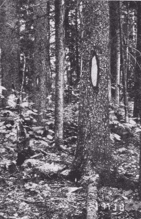
Preliminary to the actual logging are certain necessary steps. First of all is landlooking. This includes the survey of the forest land for the purpose of locating good timber. Fig. 1. Most of the woodland has previously been roughly surveyed by the government and maps made indicating which parts are private land and which are still held by the government. The boundaries of townships, sections, quarter sections, eighties, forties, etc., are indicated by "blazes" [page 8] on trees, Fig. 2, so that the "cruiser" or "looker" as he goes thru the woods can identify them with those on his oil paper map. The cruiser also studies the kinds and character of the trees, the contour of the ground, the proximity to streams,—all with the view to marketing the product. Acting on the information thus gained by the cruiser, the lumberman purchases his sections at the proper land office, or if he is less scrupulous, buys only enough to serve as a basis for operations. Enormous fortunes have been made by timber thieves, now respectable members of the community. As a further preliminary step to lumbering itself, the tote road and camp are built. The tote road is a rough road on which supplies for crew and cattle can be taken to camp from civilization.
It is barely passable for a team and a wagon, but it serves its purpose, and over it come more men and horses. Lumber for the floors and roofs of the shanties and for the rude pieces of furniture that will be needed, tarred paper to make the roofs tight, a few glazed window sashes, a huge range and a number of box stoves, dishes and kitchen utensils, a little stock of goods for the van, blankets by the dozen and score, and countless boxes and barrels and bags of provisions.1
Footnote 1: Hulbert: The Lumber Jack; Outlook, 76: 801, April 2, '04.
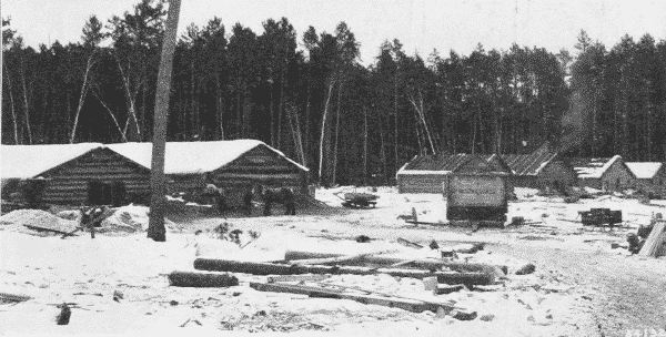
The camp itself, Fig. 3, is built of logs, roofed with plank, covered with heavy tar paper, and dimly lighted. There are usually five buildings,—the men's camp, the cook camp, the office, the barn, and the blacksmith's shop. Many camps accommodate from eighty to one hundred men. The men's camp is filled with bunks and is heated by a stove and in general roughly furnished. Cooking and eating are done in the cook camp, where the cook and his assistant, the "cookee," sleep. The office is occupied by the foreman, log-sealers [page 9] and clerks. Here the books and accounts are kept, and here is the "van," stocked with such goods as will supply the immediate needs of the lumber jacks.
Before winter sets in the main road is built, Fig. 15, p. 17, very carefully graded from the camp down to the nearest mill or railway siding, or oftener to the stream down which the logs are to be floated. This road has to be as wide as a city street, 25 feet. The route is carefully chosen, and the grade is made as easy as possible. Much labor is spent upon it, clearing away stumps and rocks, leveling up with corduroy, building bridges strong enough to carry enormous loads, and otherwise making it as passable as can be; for when needed later, its good condition is of first importance. This main road is quite distinct from and much superior to the tote road.
At intervals alongside the main road, small squares called skidways are cleared of brush and in each of them two tree trunks, "skids," are laid at right angles to the road. On these the logs, when cut later, are to be piled. Back from the skidways, into the woods the swampers cut rough, narrow roads called dray roads or travoy roads,—mere trails sufficiently cleared of brush to allow a team of horses to pull a log thru.
[page 10]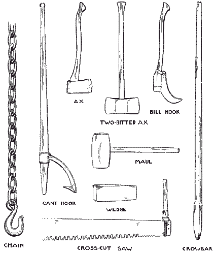
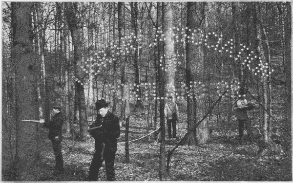
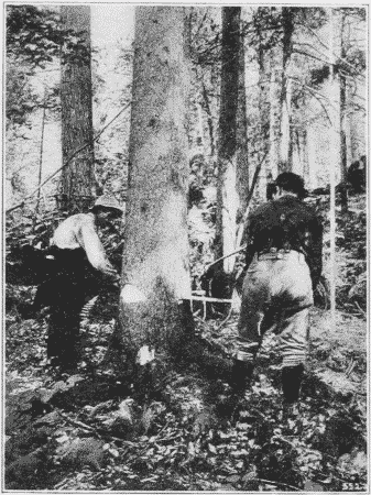
All these are operations preliminary to the felling of trees. The tools commonly used in logging are shown in Fig. 4. When everything is ready for felling, the "fitter" goes ahead marking each tree to be felled and the direction in which it is to fall by cutting a notch on that side. Then come the sawyers in pairs, Fig. 5. First they chop a deep gash on the side of the tree toward which it is to fall, and then from the opposite side begin cutting with a long, Tuttle-tooth, crosscut-saw. The saw is a long, flexible ribbon of steel, with handles so affixed to each end that they can be removed easily. The cut is made on the pulling stroke, and hence the kerf can be very narrow. As soon as the saw is well within the trunk, the sawyers drive iron wedges into the kerf behind it, partly to keep the weight of the trunk from binding the saw, and partly to direct its fall. Then the saw is pulled back and forth, and the wedges [page 11] driven in farther and farther, until every stroke of the maul that drives them sends a shiver thru the whole tree. Just as the tree is ready to go over, the saw handle at one end is unhooked and the saw pulled out at the other side. "Timber!," the men cry out as a warning to any working near by, for the tree has begun to lean slightly. Then with a hastening rush the top whistles thru the air, and tears thru the branches of other trees, and the trunk with a tremendous crash strikes the ground. Even hardened loggers can hardly keep from shouting, so impressive is the sight of a falling giant tree.
All this seems simple enough in outline, but the actual execution requires considerable skill. Trees seldom stand quite vertical, there is danger of lodging in some other tree in thick woods, and it is therefore necessary to throw trees quite exactly. Some men become so expert at this that they can plant a stake and drive it into the [page 12] ground by the falling trunk as truly as if they hit it with a maul. On the other hand, serious accidents often happen in falling trees. Most of them come from "side winders," i. e., the falling of smaller trees struck by the felled trees.
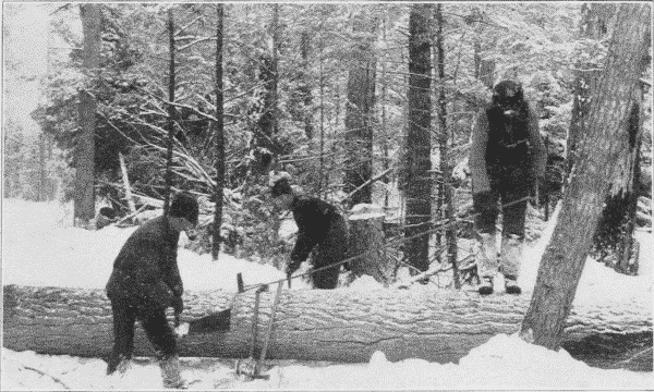
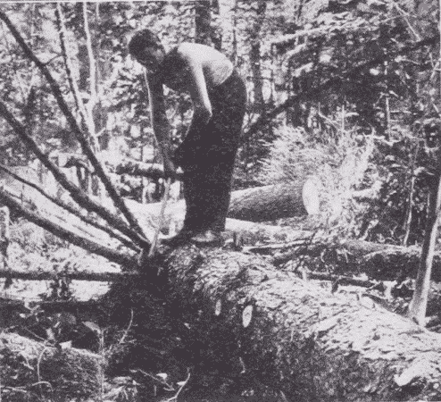
After "falling" a tree, the sawyers mark off and saw the trunk into log lengths, Fig. 6, paying due attention to the necessity of avoiding knots, forks, and rotten places, so that some of the logs are eighteen feet, some sixteen feet, some fourteen feet, and some only twelve feet in length. Meanwhile the swampers trim off the branches, Fig. 7, a job requiring no little skill, in order that the trunk may be shaved close but not gashed.
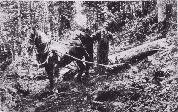
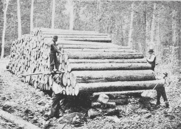
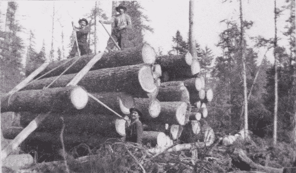
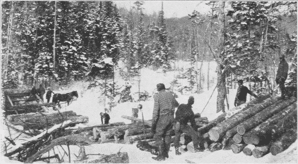
This finishes the second group of operations, the felling. Next the logs are dragged out to the dray roads, Fig. 8. A heavy pair of tongs, like ice-tongs, is attached to one end, and the log is snaked out by horses to the skidway. If the log is very heavy, one end is put on a dray. By one way or another the log is dragged out and across the two parallel skids, on which it is rolled by cant-hooks to the end of skids toward the road way. If other logs already occupy the skids, each new log as it arrives is piled on the first tier. As the pile grows higher, each log is "decked," that is, rolled up parallel poles laid slanting up the face of the pile, by means of a chain passed under and over the log and back over the pile, Fig. 11. A horse hitched to the end of the chain hauls up the log, which is guided by the "send-up men" with their cant-hooks.
Once piled the logs are "scaled," that is measured in order to compute the number of board feet in them, Fig. 9. The scaler generally has an assistant, for logs in large piles must be measured at both ends in order to determine which is the top, the body of the log being out of sight. When measured each end of the log is stamped with a hammer with the owner's mark, by which it can afterward be identified. Here the logs rest and the felling and skidding continue until deep snow falls and then the sleigh haul begins.
For this the main road is especially prepared. First the road is carefully plowed with an immense V plow, weighted down by logs. To the plow are attached fans. Only an inch or two of snow is left on the ground by this plow, which is followed by another special plow to gouge the ruts, and by a gang of "road monkeys" who clear the road thoroly. Then follows an immense tank set on runners and holding perhaps seventy-five barrels of water, and so arranged as to flood the road from holes in the bottom of the tank, a sort of rough road sprinkler, Fig. 10. The sprinkler goes over the road again and again until the road is covered by a clear, solid sheet of ice often [page 15] two feet thick, extending from the skidways to the banking grounds. This ice road is one of the modern improvements in logging. Once finished, these roads are beautiful pieces of construction with deep, clear ruts. They have to be constantly watched and repaired, and this is the work of the "road monkeys." If possible the road has been made entirely with down grades but some of these are so steep that a man must be prepared with sand or hay to check too headlong a descent.
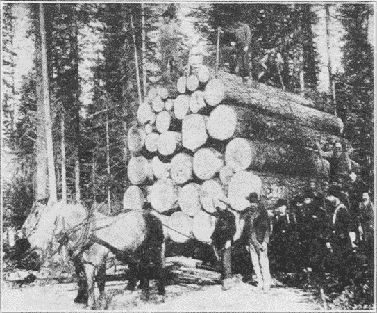
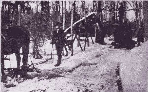
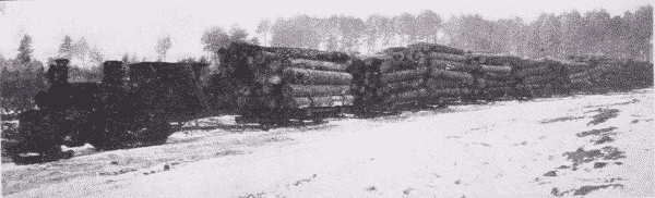
When all is ready the sleigh haul begins. Piling on the sleighs or bobs, Fig. 12, is similar to piling on the skidways, but more difficult, for the load has to be carefully balanced, Fig. 13. Chains bind the loads but the piling is only too apt to be defective, and the whole load "squash out" with a rush. It is a time of feverish activity. The sprinklers are at work till after midnight, the loaders are out long before daylight. The blacksmith is busy with repairs, the road monkeys work [page 16] overtime, and the cook works all the time. "Everybody works." The haul itself is full of excitement. The ponderous load of logs, weighing anywhere from eight to thirty-five tons has to be conducted largely by its own momentum down this glassy road. If a horse fall nothing can save its life. If the runners get out of the ruts, the whole load, driver and all, is likely to be upset. It is an extremely hazardous job, Fig. 15.
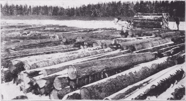
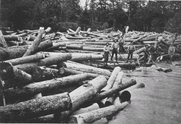
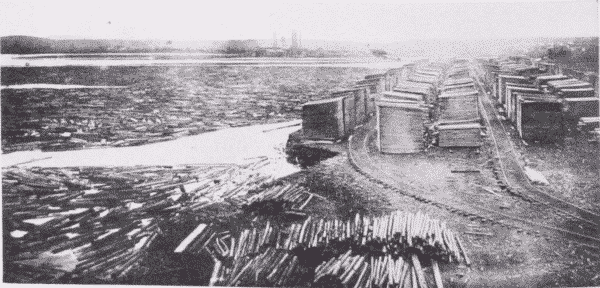
As each load comes down to the banking grounds, Fig. 14, or log dump, it is stopped opposite long parallel skids. The wrapping chains are unhooked and the lower log on the skid side is worked out with cant-hooks till the whole load flattens out. The logs are then "decked" on immense piles, sometimes a mile long and filling the whole river from bank to bank. A decking chain 300 feet long is sometimes required to roll the logs to their proper places. Here the logs rest till the spring freshets come. This completes the transportation by land.
With the coming of the spring thaw, the river bed is filled with a freshet of water which seizes and carries the logs down stream. Many on the banks, however, have to be started on their way, and this is called "breaking out the roll ways." They often start on their water journey with a great crash.
[page 17]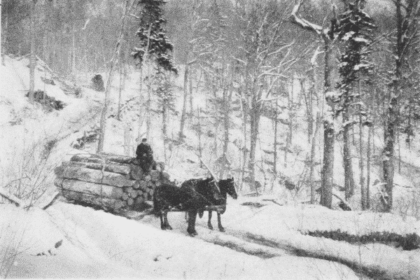
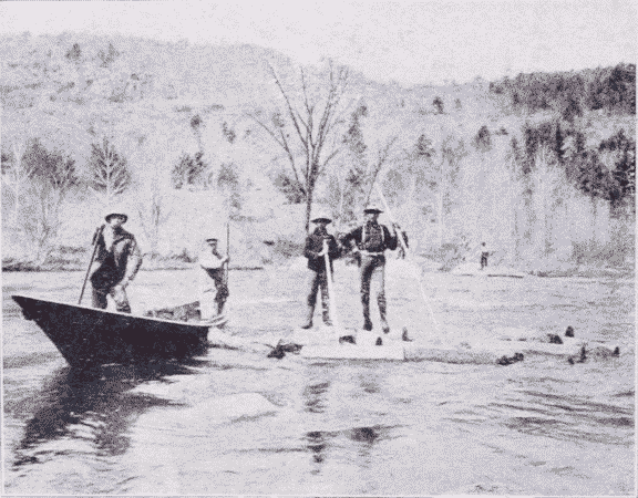
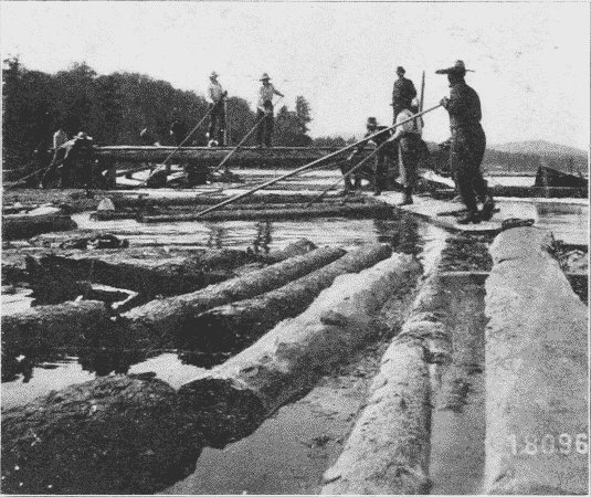
Now comes the drive, an arduous and often perilous task. Some of the men are stationed along the shores to prevent the logs from lodging or floating into bays or setbacks. Some stand at the heads of bars or islands, where with pike poles they shove off the logs that might stop there and form a jam; others follow "sacking the rear" to clean out such logs as may have become stranded. This "sacking the rear" takes most of the time, Fig. 16. While "on the drive" men often work fourteen hours a day, a good part of the time up to their waists in ice water. Their boots are shod with "caulks," or [page 18] spikes, to keep them from slipping on the logs, and they carry either pike poles or peaveys, Fig. 17. The latter are similar to cant-hooks, except that they have sharp pikes at their ends. So armed, they have to "ride any kind of a log in any water, to propel a log by jumping on it, by rolling it squirrel fashion with the feet, by punting it as one would a canoe; to be skilful in pushing, prying, and poling other logs from the quarter deck of the same cranky craft." Altho the logs are carried by the river, they have to be "driven" with amazing skill and bravery.
The climax of hardship and courage is reached when a "jam" is formed, Fig. 18. Sometimes one or two logs are caught in such a way as to be locked or jammed and then soon other logs begin to accumulate behind them, till the whole river is full of a seemingly inextricable mass. Sometimes these jams can be loosened by being pulled apart, one log at a time. A hundred men can pull out an amazing number of logs in a day. The problem always is to set free or cut out certain "key" logs, which lock the whole mass. Following is a description by Stewart Edward White of the breaking of such a jam:
The crew were working desperately. Down on the heap somewhere, two logs were crossed in such a manner as to lock the whole. They sought those logs.
Thirty feet above the bed of the river six men clamped their peaveys into the soft pine; jerking, pulling, lifting, sliding the great logs from their places. Thirty feet below, under the threatening face, six other men coolly picked out and set adrift one by one, the timbers not inextricably imbedded. From time to time the mass creaked, settled, perhaps even [page 19] moved a foot or two; but always the practised rivermen, after a glance, bent more eagerly to their work. * * * Suddenly the six men below the jam scattered. * * * holding their peaveys across their bodies, they jumped lightly from one floating log to another in the zig-zag to shore. * * *
In the meantime a barely perceptible motion was communicating itself from one particle to another thru the center of the jam. * * * The crew redoubled its exertion, clamping its peaveys here and there, apparently at random, but in reality with the most definite of purposes. A sharp crack exploded immediately underneath. There could no longer exist any doubt as to the motion, altho it was as yet sluggish, glacial. Then in silence a log shifted—in silence and slowly—but with irresistible force * * * other logs in all directions up-ended. * * *
Then all at once down by the face something crashed, the entire stream became alive. It hissed and roared, it shrieked, groaned, and grumbled. At first slowly, then more rapidly, the very fore-front of the center melted inward and forward and downward, until it caught the fierce rush of the freshet and shot out from under the jam. Far up-stream, bristling and formidable, the tons of logs, grinding savagely together, swept forward. * * *
Then in a manner wonderful to behold, thru the smother of foam and spray, thru the crash and yell of timbers, protesting the flood's hurrying, thru the leap of destruction, the drivers zigzagged calmly and surely to the shore.
Sometimes cables have to be stretched across the chasm, and special rigging devised to let the men down to their dangerous task and more especially to save them from danger when the crash comes.
[page 20]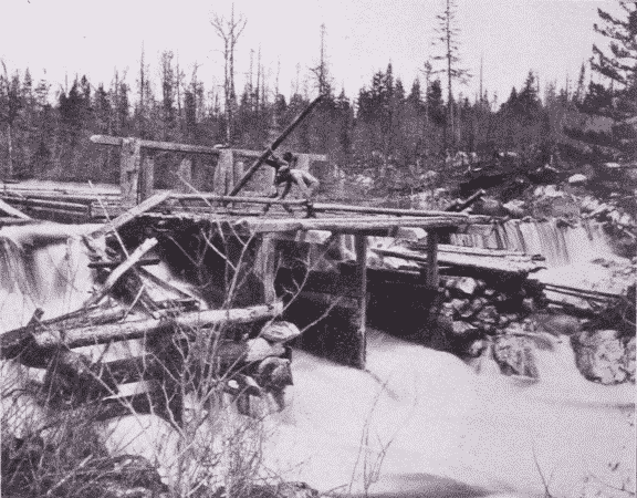

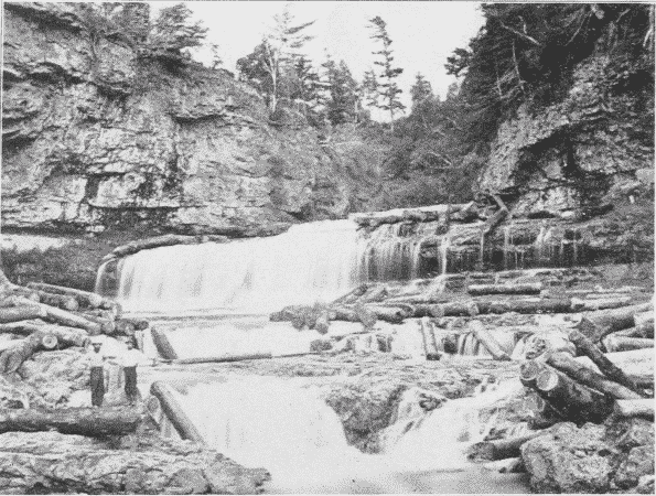
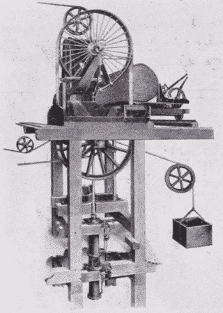
In case such efforts are unavailing, it is necessary to "shoot" the jam with dynamite. Another device resorted to where the supply of water is insufficient is the splash-dam, Fig. 20. The object is to make the operator independent of freshets, by accumulating a head of water and then, by lifting the gates, creating an artificial freshet, sufficient to float the timber down stream.
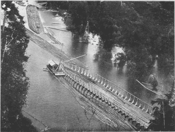
Thus by one means and another, the logs are driven along until caught by a boom, Fig. 21, which consists of a chain of logs stretched across the river, usually at a mill. Since the river is a common carrier, the drives of a number of logging companies may float into the mill pond together. But each log is stamped on both ends, so that it can be sorted out, Fig. 22, and sent into the boom of its owner.
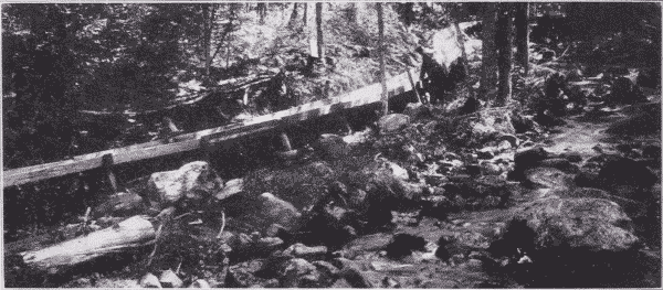
The operations described above are those common in the lumber regions of the northeast and the Lake States. But special conditions produce special methods. A very effective device where streams are small is the flume, Fig. 23. This is a long wooden trough thru which water is led, and the logs floated end on. It is sometimes many miles long; in one case in California twenty-five miles.
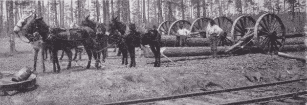
[page 22]In the South where there is no snow, logs are largely brought out to the railway or river by being hung under immense two-wheeled trucks, called slip-tongue carts, drawn by mules, Fig. 24. The wheels are nearly eight feet in diameter.
Some kinds of wood are so heavy that they will not float at all, and some sink so readily that it does not pay to transport them by river. In such cases temporary railways are usually resorted to.
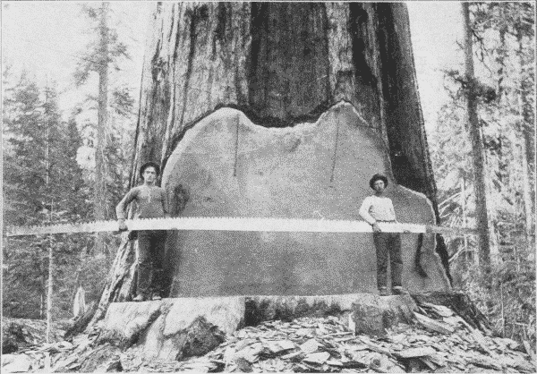
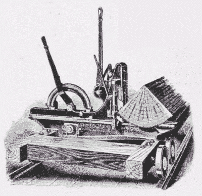
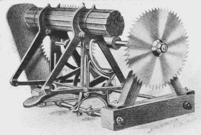
On the Pacific coast, where the forests are dense, the trees of enormous size, and no ice road is possible, still other special methods have been devised. On so great a scale are the operations conducted that they may properly be called engineering feats. Consider for a moment the size of the trees: red fir ranges from five to fifteen feet in diameter, is commonly two hundred fifty feet high, and sometimes three hundred twenty-five feet high. The logs are commonly cut twenty-five feet long, and such logs often weigh thirty to forty tons [page 23] each, and the logs of a single tree may weigh together one hundred fifty tons. The logging of such trees requires special appliances. Until recently all the improved methods were in forms of transportation, the felling still being done by hand with very long saws, Fig. 25, but now even the felling and sawing of logs in the forest is partly done by machinery.
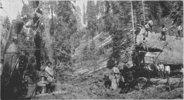
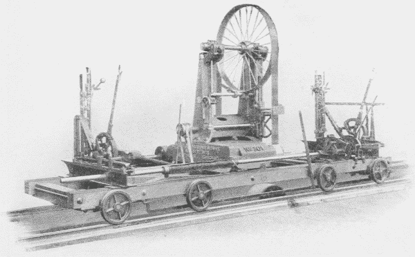
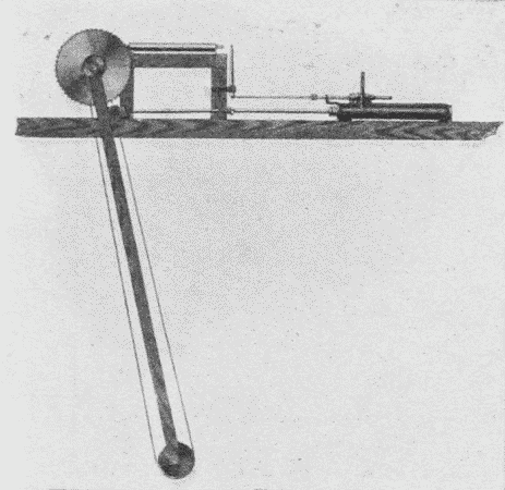
To work the saw, power is supplied by a steam or gasoline engine mounted upon a truck which can be taken readily from place to place. As the maximum power required is not over ten-horse-power, the apparatus is so light that it can be moved about easily. The saw can be adjusted to cut horizontally, vertically, or obliquely, and hence is used for sawing into lengths as well as for felling.
Falling beds. Since the weight of a two hundred fifty foot fir is such that if the impact of its fall be not gradually checked the force with which it strikes the ground may split the trunk, a bed for its fall is prepared by the swampers. Usually piles of brush are placed as buffers along the "falling line" so that the trunk will strike these. If the tree stands on the hill side, it is thrown up hill, in order to shorten the fall.
After the felling comes the trimming of branches and knots and "rossing" of bark, to lessen the friction in sliding along the skidway.
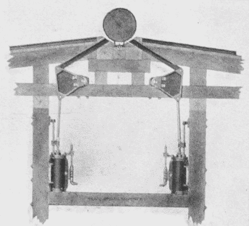
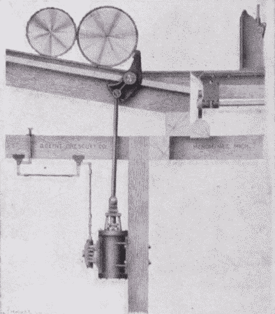
The skidway. By the skidway in the Puget Sound region is meant a corduroy road. This is constructed of trunks of trees ranging from a foot to two feet in diameter. These are "rossed," that is, stripped of their bark and laid across the road, where they are held in place by pegs driven into the ground, and by strips spiked upon the tops of the logs. If possible they are laid in swampy places to keep the surface damp and slippery. At turns in the road, pulleys are hung, thru which the hauling cables pass. The skidway runs to the railway siding or water's edge. Over these skidways the logs are hauled out by various means. Formerly "strings" of oxen or Percheron horses were used, but they are now largely superseded by some form of donkey engine, Fig. 26. These are placed at the center of a "yard."
Yarding is the skidding of logs to the railway or water way by means of these donkey engines. Attached to the donkey engine are two drums, one for the direct cable, three-fourths to one inch in diameter and often half a mile long, to haul in the logs, the other for the smaller return cable, twice as long as the direct cable and used to haul back the direct cable. At the upper end of the skidway, when the logs are ready to be taken to the railway or boomed, they are fastened together, end to end, in "turns" of four or more. The direct cable is attached to the front of the "turn", and the return cable to the rear end. By winding the direct cable on its drum, the "turn" is hauled in. The return cable is used to haul back the end [page 25] of the direct cable, and also, in case of a jam, to pull back and straighten out the turn. Instead of a return cable a horse is often used to haul out the direct cable. Signaling from the upper end of the skidway to the engineer is done by a wire connected to the donkey's whistle, by an electric bell, or by telephone.
Sometimes these donkey engines are in relays, one engine hauling a turn of logs to within reach of the next one, which passes it on to the next until the siding is reached.
Where there are steep canons to be crossed, a wire trolley may be stretched and the great logs carried over suspended from it.
In the South a complicated machine called a steam skidder, Fig. 27, equipped with drums, booms, etc., is much used both for skidding in the logs and then for loading them on the cars. It is itself mounted on a flat car.
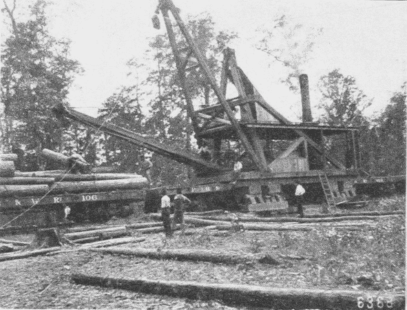
An improvement on this is the locomotive boom derrick which is widely used both on the Pacific coast and of late in the Lake Superior region. It is a combined locomotive, skidder and loader. Its most unique feature is that it can be lifted off the track so as to allow flat cars to run underneath it. This feat is accomplished thus: A device, which is something like that used in elevating the bodies of coal wagons, lifts the engine several feet above the rails. Then steel legs, which are curved outwardly, are lowered until the shoes which [page 26] are attached to them rest on the outward end of the railroad ties. The truck of the locomotive is then folded up under it out of the way and cars can run under it, the curved legs giving plenty of clearance. The derrick attached is of the breast type, the two legs being firmly fastened. When anchored the engine can be used either for skidding or loading. For skidding, there are two cables, one being run out while the other is being wound on its drum.
In loading, the machine is located so that the empty car will be directly in front of it, and then the logs are lifted up and placed on the car by the derrick. When the car is loaded the machine can either move on to the next car, or pull it under itself into place. With the help of four men it can load from 125,000 to 150,000 feet of timber in a day. By means of the cable it can make up a train, and then by lowering the truck and raising the legs out of the way, it is converted into a locomotive and hauls the train away to the mill or railway station at the rate of three or four miles at hour.
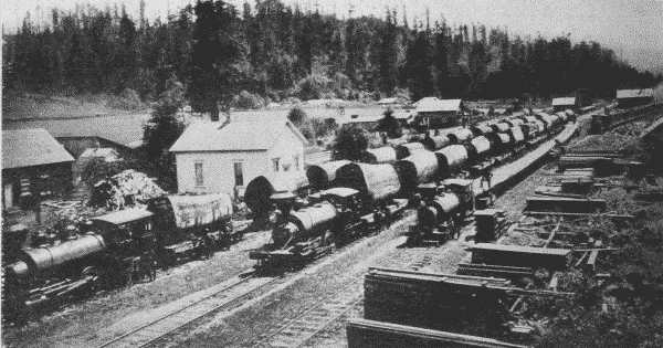
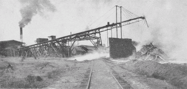
As forests are cut away along the water courses, railways have to be resorted to more and more, Fig. 28. This has had a stimulative effect on the logging business, for now the logger is independent of the snow. On account of the steep grades and sharp curves often necessary in logging railways, a geared locomotive is sometimes used, Fig. 29. It can haul a train of twenty loaded cars up a twelve per cent grade. The geared engine has also been used as a substitute for cable power, in "yarding" operations. The "turns" of logs are drawn over the ground between the rails, being fastened to the rear of the engine by hook and cable. This has proved to be a very economical use of power and plant.
[page 27]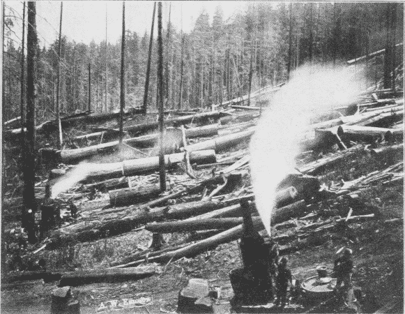
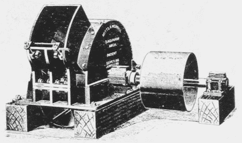
Another method of traction where the woodland is open enough is with a traction engine. The ones employed have sixty to one hundred horse power. The great logs may be placed on wood rollers, as a house is when moved, or the logs may be hauled in on a low truck with broad wheels. The "tractor" hauls the log direct to the railway if the distance is not too great.
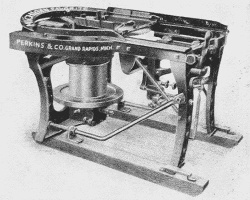
In Northern Michigan a "snow locomotive," Fig. 31, is coming into use, which has tremendous tractive power, hauling one hundred to one hundred fifty tons of lumber over snow or ice. It moves on runners, but there is between them a large cylinder armed with teeth. This cylinder can be raised or lowered by the operator as it moves over the surface of the ground. The teeth catch in the snow or ice, and since the cylinder is heated by the exhaust steam, it melts and packs the snow for the trucks following it. The drum is six feet in diameter, with walls an inch and a half thick, and it weighs seven tons. It is used in all sorts of places where horses cannot go, as in swamps, and by substituting wheels for runners it has even been used on sand.
In the Canadian lakes there has been devised a queer creature called an "alligator," a small and heavily equipped vessel for hauling the logs thru the lakes. When its operations in one lake are finished, a wire cable is taken ashore and made fast to some tree or other safe anchorage, the capstan on its forward deck is revolved by steam and the "alligator" hauls itself out of the water across lots to the next lake and begins work there.
[page 29]The greatest improvement in water transportation is the giant raft, Fig. 30. When such a raft is made up, logs of uniform length are placed together, the width of the raft being from sixty to one hundred feet and its length, one thousand feet or more. It may contain a million board feet of timber. The different sections are placed end to end, and long boom sticks, i. e., logs sixty to seventy feet long, are placed around them to bind the different sections together, and finally the whole mass is heavily chained. Such a raft has been towed across the Pacific.
References*
River Lumbering.
Pinchot, Primer, II, pp. 40-53.
White, Blazed Trail, pp. 5-15, 25, 38-39, 52-53, 63-65, 72-85, 91-99, 113-125, 134, 181-196, 216-229, 257, 268, 320-343, 355, 365 ff.
For. Bull., No. 34, pp. 33-41, Fox.
White, Jun. Mun., 10: 362.
Hulbert, Outl., 76; 801.
Wood Craft, 4: 55.
Smith, K., World's Work, 7: 4435.
Mechanical Methods.
World's Work, 7: 4435.
Outl., 76: 812.
Bruncken, p. 86.
Bruncken, pp. 76-87.
Munn, Cosmop., 37: 441.
Roth, First Book, pp. 133-174.
Hovey-King, Rev. of Rev., 27: 317.
Jones, Cosmop., 15: 63.
Price, World's Work, 5: 3207.
For. Bull., No. 61.
Cassier, 29: 443, April, '06.
Cosmop., 37: 445.
Rev. of Rev., 28: 319.
* For general bibliography see p. 4.
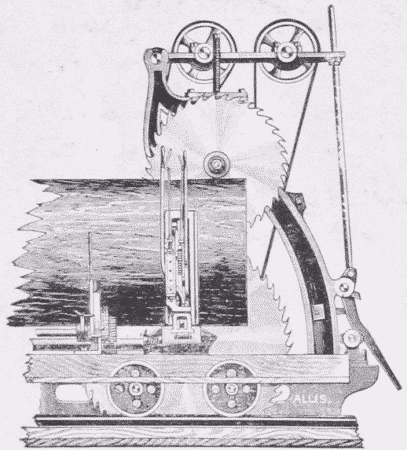
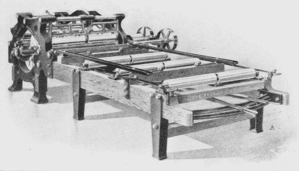
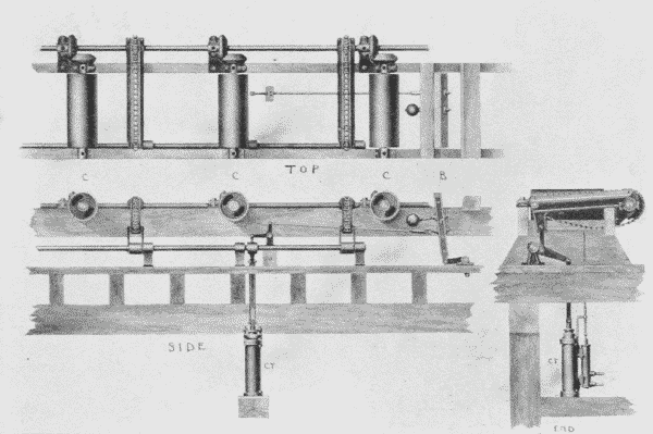
[page 30]The principal saws in a mill are of three kinds, the circular, Fig. 32, the gang, Fig. 33, and the band, Fig. 34. The circular-saw, tho very rapid, is the most wasteful because of the wide kerf, and of course the larger the saw the thicker it is and the wider the kerf. The waste in sawdust is about one-fifth of the log. In order to lessen this amount two smaller saws, one hung directly above the other, have been used. One saws the lower half of the log and the other the upper half. In this way, it is possible to cut very large logs with the circular-saw and with less waste. The circular-saw is not a perfectly flat disc, but when at rest is slightly convex on one side and concave on the other. This fullness can be pushed back and forth as can the bottom of an oil-can. When moving at a high rate of speed, however, the saw flattens itself by centrifugal force. This enables it to cut straight with great accuracy.
A gang-saw is simply a series of straight saw-blades set in a vertical frame. This has a reciprocating motion, enabling it to cut a log into a number of boards at one time. It has this drawback, that it must cut the size of lumber for which it is set; that is, the sawyer has no choice in cutting the thickness, but it is very economical, wasting only one-eighth of the log in sawdust. A special form is the flooring gang. It consists of a number of saws placed one inch apart. Thick planks are run thru it to saw up flooring.
[page 31]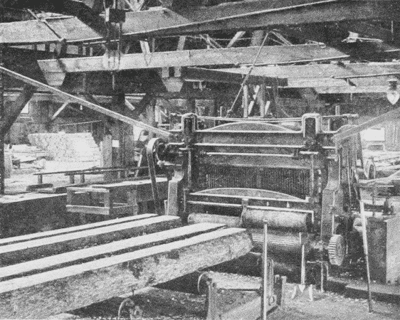
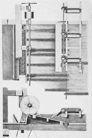
The band-saw is fast displacing the other two, wherever it can be used. It cuts with great rapidity and the kerf is narrow. When first used it could not be depended upon to cut straight, but by utilizing the same principle that is used in the circular-saw, of putting the cutting edge under great tension by making it slightly shorter than the middle of the saw, it now cuts with great accuracy. Band-saws are now made up to 12 inches wide, 50 feet long, and run at the rate of 10,000 feet a minute. They are even made with the cutting teeth on both edges, so that the log can be sawed both going and coming. This idea was unsuccessful until the invention of the telescopic band-mill, Fig. 35. In this the entire mechanism carrying [page 32] the wheels on which the band-saw revolves can be moved up and down, so as to bring the point where the saw leaves the upper wheel as close to the top of the different sized logs as possible.
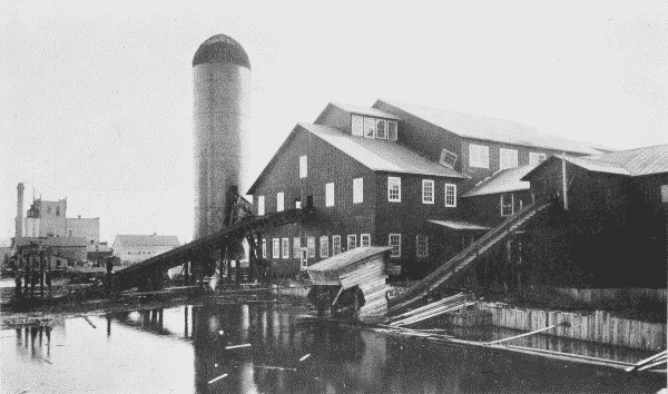
The usual modern mill is a two story building, Fig. 37, built at a convenient locality both for receiving the logs and for shipping the lumber. Whether the logs arrive by water or by rail, they are, if possible, stored in a mill-pond until used in order to prevent checking, discoloration, decay, and worm attack. From the pond they are hauled up out of the water on to a "jack-ladder," by means of an endless chain, provided with saddles or spurs which engage the logs and [page 33] draw them up into the second story on to the log slip, Fig. 36.
After the logs have entered the mill, they are inspected for stones lodged in the bark, and for spikes left by the river men, and then measured. Under the log-slip is the steam "flipper" or "kicker," Fig. 38, by means of which the scaler or his assistant, throwing a lever, causes the log to be kicked over to one side or the other, on to the log-deck, an inclined floor sloping toward the saw-carriage. Down this the log rolls until stopped by a log-stop, or log-loader, Fig. 39, a double-aimed projection, which prevents it from rolling on the carriage till wanted. This stop is also worked by steam. By letting the steam into the cylinder which controls it, one log is rolled over on the carriage and the next one held. The log on the carriage is at once "dogged," that is, clamped tight by iron dogs, the carriage is set for the proper cut, and moves forward to the saw which cuts off the first slab. The carriage is then "gigged" or reversed. This operation offsets the carriage one-eighth of an inch so that the log returns entirely clear of the saw. In the same way two or three 1" boards are taken off, the dogs are then knocked out, and the log canted over half a revolution. This is done by means of the "steam nigger," Fig. 40, a long, perpendicular toothed bar which comes up thru the floor, engages the log, and turns it over till the sawn side comes up against the knees of the carriage. [page 35] The log is dogged again and a second slab and several boards are taken off. The log or "stock" as it is now called, is 10", 12", 14", or 16" thick; the "nigger" then gives it a quarter-turn, leaving it lying on a sawn side. It is dogged again, and all sawn up except enough to make a few boards. This last piece is given a half-turn, bringing the sawn side against the knees, and it is sawn up. Each board as it is sawn off is thrown by the board-flipper or cant-flipper,2 Fig. 41, on to the "live rollers," which take it to the next process. Another log comes on the carriage and the process is repeated.
Footnote 2: A "cant" is a squared or partly squared log.
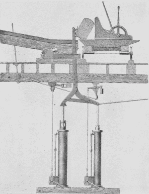


Fig. 41. Steam Cant-Flipper. This machine is used to move cants, timber, or lumber from live rollers to gangs, band resaw mills, or elsewhere. The timber is discharged upon skid rollers, as shown, or upon transfer chains. |
The saw-carriage, Fig. 42, is propelled forward and back by a piston running in a long cylinder, into either end of which steam can be turned by the operator.
As the sawn boards fall off the log, they land on "live," that is, revolving rollers, which carry them along at the rate of 200 to 250 feet a minute. Stops are provided farther along to stop the boards wherever wanted, as at the edger, Fig. 43, or the slasher. From the live rollers the [page 36] boards are transferred automatically, Fig. 44, by chains running at right angles to the rollers and brought within reach of the edger man. About one-third of the boards of a log have rough edges, and are called "waney." These must go thru the edger to make their edges parallel. The edger man works with great speed. He sees at once what can be made out of a board, places it in position and runs it thru. From the edger the boards are carried to the trimmer, which cuts the length. The lumberman's rule is to "cut so that you can cut again." The so-called 16' logs are really 16' 6". The trimmer, Fig. 45, now trims these boards to 16' 1", so that if desired they can still be cut again. The trimmer may be set to cut at any desired length according to the specifications.
The boards are now graded as to quality into No. 1, No. 2, etc., Fig. 46, and run out of the mill, to be stacked up in piles, Fig. 47. Big timbers go directly from the saw on the rolls to the back end of the mill, where the first end is trimmed by a butting-saw or cut-off-saw which swings, Fig. 48. The timber is then shoved along on dead rolls and the last end [page 39] trimmed by the butting-saw to a definite length as specified, and shoved out.
One of the most remarkable features of the modern mill is its speed. From the time the log appears till the last piece of it goes racing out of the mill, hardly more than a minute may have elapsed.
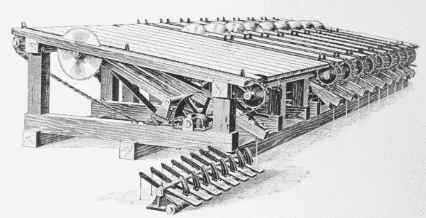
A large part of the problem of sawmilling is the disposal of the waste. The first of these is the sawdust. In all first class mills, this together with shavings (if a planing-mill is combined) is burned for fuel. It is sucked up from the machines and carried in large tubes to the boiler-room and there is mechanically supplied to the fires. The slabs, once considered as waste, contain much material that is now utilized. From the live rolls, on which all the material falls from the main band-saw, the slabs are carried off by transfer chains, and by another set of five rollers to the "slasher," Fig. 50, which consists of a line of circular-saws placed 4' 1" apart. This slasher cuts up the slabs into lengths suitable for lath or fence-pickets, Fig. 49. Or they can be resawn into 16" lengths for shingles or fire-wood.
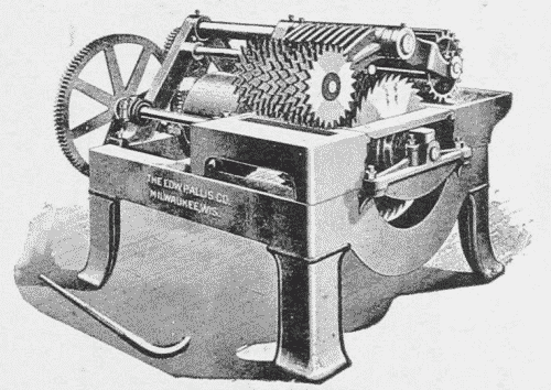
From the "slasher" the 4' 1" lengths are carried on by traveling platforms, chains, etc., to the lath-machines, Fig. 51, where they are sawn up, counted as sawn, bound in bundles of 100, trimmed to exactly 4' in length and sent off to be stored. The shingle bolts are picked off the moving platforms by men or boys, and sent to the shingle-machine, Fig. 52, where they are sawn into shingles and dropped down-stairs to [page 41] be packed. Shingle-bolts are also made from crooked or otherwise imperfect logs.
Of what is left, a good part goes into the grinder or "hog," Fig. 53, which chews up all sorts of refuse into small chips suitable for fuel to supplement the sawdust if necessary. Band-saws make so little dust and such fine dust that this is often necessary.
If there is any refuse that cannot be used at all it goes to the scrap-pile, Fig. 54, or to the "consumer," the tall stack shown in Fig. 37, see p. 33.
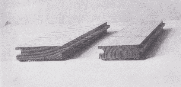
Boards ordinarily sawn from logs are "slash-sawn," i. e., they are tangential or bastard, each cut parallel to the previous one. By this process, only the central boards would be radial or "rift" boards.
But, for a number of reasons, radial boards are better. They warp less because the annual rings cross the board more evenly. Yellow pine flooring that is rift-sawn is more valuable than slash-sawn, because the edge of the annual rings makes a more even grain, Fig. 55. Where slash-grained flooring is used, the boards should be laid so that the outside of each board will be up in order that the inner rings may not "shell out."
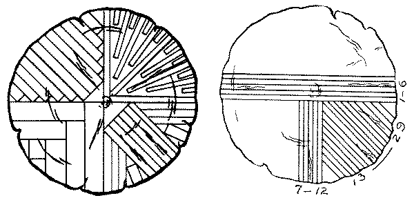
[page 42]In sawing oak for valuable furniture or trim, the log is first "quartered" and then the quarters sawn up as nearly radially as is desired. There are various methods of cutting quartered logs, as illustrated in Fig. 56.
In making staves for water-tight barrels, it is essential that they be cut radially in the log, in order that the staves be as non-permeable to water as possible.
References*
Trout, Cassier 11: 83, 184.
Woodcraft 5: 56, May '06.
* For general bibliography see p. 4.
[page 44]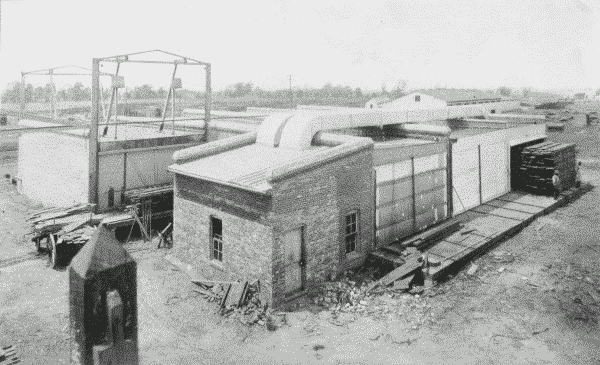
The seasoning of wood is important for several reasons. It reduces weight, it increases strength, it prevents changes in volume after it is worked into shape, and it prevents checking and decay. Decay can also be prevented by submergence and burying, if by so doing logs are kept from fungal attacks. The piles of the Swiss Lake dwellings, which are in a state of good preservation, are of prehistoric age. Wood under water lasts longer than steel or iron under water. But for almost all purposes wood has to be dried in order to be preserved. The wood is cut up, when green, to as thin pieces as will be convenient for its use later, for the rate of drying depends largely upon the shape and size of the piece, an inch board drying more than four times as fast as a four inch plank, and more than twenty times as fast as a ten inch timber.
There are various methods of seasoning:
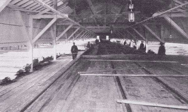
(1) Natural or air-seasoning is the most common, and in some respects the best. In this method, the wood is carefully and regularly piled in the seasoning-yard, so as to be protected as far as possible from sun and rain, but with air circulating freely on all sides of the boards, Fig. 47, see p. 38. To accomplish this, "sticking" is employed, i. e., strips of wood are placed crosswise close to the ends and at intervals between the boards. In this way the weight of the superposed boards tends to keep those under them from warping. The pile is skidded a foot or two off the ground and is protected above by a roof made of boards so laid that the rain will drain off.
Fire-wood is best dried rapidly so that it will check, making air spaces which facilitate ignition, but lumber needs to be slowly dried in cool air so that the fibers may accommodate themselves to the change of form and the wood check as little as possible. Good air-drying consumes from two to six years, the longer the better.
[page 46](2) Kiln-drying or hot-air-seasoning is a much more rapid process than air-seasoning and is now in common use, Fig. 57. The drying is also more complete, for while air-dried wood retains from 10% to 20% of moisture, kiln-dried wood may have no more than 5% as it comes from the kiln. It will, however, reabsorb some moisture from the air, when exposed to it.
The wood of conifers, with its very regular structure, dries and shrinks more evenly and much more rapidly than the wood of broad-leaved trees, and hence is often put into the kiln without previous air-drying, and dried in a week or even less time.
Oak is the most difficult wood to dry properly. When it and other hardwoods are rapidly dried without sufficient surrounding moisture, the wood "case-hardens," that is, the outer part dries and shrinks before the interior has had a chance to do the same, and this forms a shell or case of shrunken, and often checked wood around the interior which also checks later. This interior checking is called honeycombing. Hardwood lumber is commonly air-dried from two to six months, before being kiln-dried. For the sake of economy in time, the tendency is to eliminate yard-drying, and substitute kiln-drying. Kiln-drying of one inch oak, takes one or two weeks, quarter-sawn boards taking one and a half times as long as plain-sawn.
The best method of drying is that which gradually raises the temperature of both the wood and of the water which it contains to the point at which the drying is to take place. Care is therefore taken not to let the surface become entirely dry before the internal moisture is heated. This is done by retaining the moisture first vaporized about the wood, by means of wet steam. When the surface is made permeable to moisture, drying may take place rapidly. Curtains of canvas are hung all around the lumber on the same principle that windows in newly plastered buildings are hung with muslin. The moisture is absorbed on the inner surface of the curtain and evaporates from the outer surface. Improvements in kiln-drying are along the line of moist air operation. In common practice, however, the moist air principle is often neglected.
There are two methods in operation, the progressive method and the charge method. In the progressive, the process is continuous, the loads going in at one end of the kiln, and out at the other, the temperature and the moisture being so distributed in the kiln, that in passing from the green to the dry end, a load of lumber is first [page 47] moistened, then heated, and finally dried out. In the charge system, the process is intermittent, one charge being removed before a new one is admitted. This gives the best results with high grade lumber for special uses.
A modification of hot-air-seasoning is that which subjects the wood to a moderate heat in a moist atmosphere charged with the products of the combustion of fuel.
(3) Small pieces of wood may be effectively seasoned by being boiled in water and then dried. The process seems to consist of dissolving out albuminous substances and thus allowing freer evaporation. Its effect is probably weakening.
(4) Soaking in water is sometimes used as a good preparation for air-seasoning. Previous soaking hastens seasoning. River men insist that timber is improved by rafting. It is a common practice to let cypress logs soak in the swamps where they grow for several months before they are "mined out." They are eagerly sought after by joiners and carpenters, because their tendency to warp is lessened. Ebony is water-soaked in the island of Mauritius as soon as cut. Salt water renders wood harder, heavier, and more durable and is sometimes applied to ship timbers, but cannot be used with timbers intended for ordinary purposes, as the presence of salt tends to absorb atmospheric moisture.
(5) Boiling in oil is resorted to for special purposes, both for preservation and to give strength. For example, the best handscrews are so treated. The oil also prevents glue from sticking, the most frequent cause of injury to handscrews.
(6) There are a number of "impregnation" methods of preserving timber, and their practice is spreading rapidly. Of the various preservative processes, those using coal tar creosote and zinc chloride have proved most efficient. The purpose is to force the preservative into the pores of the wood, either by painting, soaking, or putting under pressure. Such impregnation methods double or treble the life of railway ties. It is now being used with great success to preserve electric wire poles, mine-props, piling, fence-posts, etc.
Wood preservation has three great advantages, it prolongs the life of timbers in use, reduces their cost, and makes possible the use of species that once were considered worthless. For example, the cheap and abundant loblolly pine can be made, by preservative methods, to take the place of high priced long-leaf pine for many purposes.
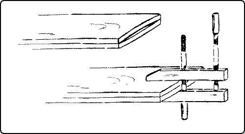
[page 48]Under the hasty methods prevalent in the mill, very little wood comes to the shop well seasoned, and it should therefore be carefully stored before using, so as to have the fullest possible air circulation around it. Where the boards are large enough, "sticking" is the best method of storage, i. e., narrow strips of wood are placed at short intervals between the pieces which are piled flat. The weight of the boards themselves helps to prevent warping. Boards set upright or on edge are likely to be distorted soon. It is often wise to press together with weights or to clamp together with handscrews boards that show a tendency to warp, putting the two concave sides together. Then the convex side is exposed and the board may straighten thus: Fig. 58. By wrapping up small boards in paper or cloth in the intervals between work on them, they may be kept straight until they are assembled.
Another precaution to take is to be sure to plane both sides of a board if either is planed, especially if the board has been exposed to air-drying for some time.
Lumber is a general term for all kinds of sawn wood. Logs may be sawn into timber, that is, beams and joists, into planks, which are 2" to 4" thick, or into boards which are from ¼" to 1¾" thick. These may be resawn into special sizes.
Lumber is measured by the superficial foot, which is a board 1" thick, 12" wide, and 12" long, so that a board 1" thick, (or ⅞" dressed) 6" wide and 12' 0" long, measures 6' B. M. (board measure). Boards 1" or more thick are sold by the "board foot" which is equivalent to 12" square and 1" thick. Boards less than 1" thick are sold by the square foot, face measure. Dressed lumber comes in sizes ⅛" less than sawn lumber. Regular sizes are:
[page 49]| ⅝ | " | dressed to | ½" | |
| ¾ | " | dressed to | ⅝" | |
| 1 | " | dressed to | ⅞" | |
| 1 | ¼ | " | dressed to | 1⅛" |
| 1 | ½ | " | dressed to | 1⅜" |
| 2 | " | dressed to | 1⅞" |
Any of these may be dressed down to thinner boards, or resawn on a special band-saw.
In ordering it is common to give the dimensions wanted, in the order of thickness, width, and length, because that is the order in which dimensions are gotten out. E. g.:
6 pcs. quar. oak, ⅞" × 6" × 3'0"
2 pcs. quar. oak, ¾" × 7½" × 15"
If a piece wanted is short the way the grain goes, the order would be the same, thus: ¾" × 11" (wide) × 6" (long). That is, "long" means the way the grain runs. It is always safe to specify in such a case. It is common when small pieces are ordered to add one-quarter to the cost for waste.
In large lots lumber is ordered thus: 800' (B. M.) whitewood, dressed 2 sides to ⅞", 10" and up. This means that the width of any piece must not be less than 10". Prices are usually given per "M," i. e., per 1000 ft.: e. g.: basswood may be quoted at $40.00 per M.
When thin boards are desired it is often economical to buy inch stuff and have it resawn.
Some lumber is also ordered by the "running" or lineal foot, especially moldings, etc., or by the piece, if there is a standard size as in fence-posts, studs, etc. Laths and shingles are ordered by the bundle to cover a certain area. 1000 4" shingles (= 4 bundles) cover 110 sq. ft. with 4" weather exposure. 100 laths (1 bundle) each ¼" × 1½" × 4'0" cover about 150 sq. ft.
There are several methods of measuring lumber. The general rule is to multiply the length in feet by the width and thickness in inches and divide by 12, thus: 1" × 6" × 15' ÷ 12 = 7½ feet. The use of the Essex board-measure and the Lumberman's board-measure are described in Chapter 4, pp. 109 and 111.
[page 50]References*
seasoning.
For. Bull., No, 41, pp. 5-12, von Schrenk.
Dunlap, Wood Craft, 6: 133, Feb. '07.
For. Circ. No. 40, pp. 10-16, Herty.
Barter, pp. 39-53.
Boulger, pp. 66-70, 80-88.
Wood Craft, 6: 31, Nov. '06.
For. Circ. No. 139.
Agric. Yr. Bk., 1905, pp. 455-464.
measuring.
Sickels, pp. 22, 29.
Goss, p. 12.
Building Trades Pocketbook, pp. 335, 349, 357.
Tate, p. 21.
* For general bibliography see p. 4.
[page 51]The hand tools in common use in woodworking shops may, for convenience, be divided into the following classes: 1, Cutting; 2, Boring; 3, Chopping; 4, Scraping; 5, Pounding; 6, Holding; 7, Measuring and Marking; 8, Sharpening; 9, Cleaning.
The most primitive as well as the simplest of all tools for the dividing of wood into parts, is the wedge. The wedge does not even cut the wood, but only crushes enough of it with its edge to allow its main body to split the wood apart. As soon as the split has begun, the edge of the wedge serves no further purpose, but the sides bear against the split surfaces of the wood. The split runs ahead of the wedge as it is driven along until the piece is divided.
It was by means of the wedge that primitive people obtained slabs of wood, and the great change from primitive to civilized methods in manipulating wood consists in the substitution of cutting for splitting, of edge tools for the wedge. The wedge follows the grain of the wood, but the edge tool can follow a line determined by the worker. The edge is a refinement and improvement upon the wedge and enables the worker to be somewhat independent of the natural grain of the wood.
In general, it may be said that the function of all cutting tools is to separate one portion of material from another along a definite path. All such tools act, first, by the keen edge dividing the material into two parts; second, by the wedge or the blade forcing these two portions apart. If a true continuous cut is to be made, both of these actions must occur together. The edge must be sharp enough to enter between the small particles of material, cutting without bruising them, and the blade of the tool must constantly force apart the two portions in order that the cutting action of the edge may continue.
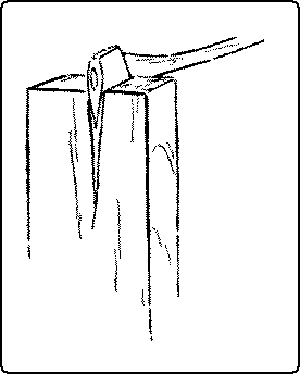
The action of an ax in splitting wood is not a true cut, for only [page 52] the second process is taking place, Fig. 59. The split which opens in front of the cutting edge anticipates its cutting and therefore the surfaces of the opening are rough and torn.
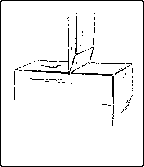
When a knife or chisel is pressed into a piece of wood at right angles to the grain, and at some distance from the end of the wood, as in Fig. 60, a continuous cutting action is prevented, because soon the blade cannot force apart the sides of the cut made by the advancing edge, and the knife is brought to rest. In this case, it is practically only the first action which has taken place.
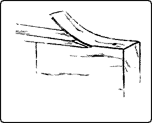
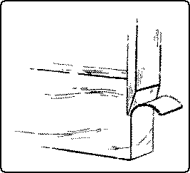
Both the actions, the cutting and the splitting, must take place together to produce a true continuous cut. The edge must always be in contact with the solid material, and the blade must always be pushing aside the portions which have been cut. This can happen only when the material on one side of the blade is thin enough and weak enough to be readily bent out of the way without opening a split in front of the cutting edge. This cutting action may take place either along the grain, Fig. 61, or across it, Fig. 62.
The bending aside of the shaving will require less force the smaller the taper of the wedge. On the other hand, the wedge must be strong enough to sustain the bending resistance and also to support the cutting edge. In other words, the more acute the cutting edge, the easier the work, and hence the wedge is made as thin as is consistent with strength. This varies all the way from hollow ground razors to cold-chisels. For soft wood, the cutting angle (or bevel, or bezel) of chisels, gouges and plane-irons, is small, even as low as 20°; for hard wood, it must be greater. For metals, it varies from 54° for wrought iron to 66° for gun metal.
Ordinarily a cutting tool should be so applied that the face nearest the material lies as nearly as possible in the direction of the cut desired, sufficient clearance being necessary to insure contact of the actual edge.
There are two methods of using edge tools: one, the chisel or straight cut, by direct pressure; the other, the knife or sliding cut.
The straight cut, Fig. 63, takes place when the tool is moved into the material at right angles to the cutting edge. Examples are: the action of metalworking tools and planing machines, rip-sawing, turning, planing (when the plane is held parallel to the edge of the board being planed), and chiseling, when the chisel is pushed directly in line with its length.
The knife or sliding cut, Fig. 64, takes place when the tool is moved forward obliquely to its cutting edge, either along or across the grain. It is well illustrated in cutting soft materials, such as bread, meat, rubber, cork, etc. It is an advantage in delicate chiseling and gouging. That this sliding action is easier than the straight pressure can easily be proved with a penknife on thin wood, or by planing with the plane held at an angle to, rather than in line with, the direction of the planing motion. The edge of the cutter then slides into the material. The reason why the sliding cut is easier, is partly because the angle of the bevel with the wood is reduced by holding the tool obliquely, and partly because even the sharpest cutting edge is notched with very fine teeth all along its edge so that in the sliding cut it acts like a saw. In an auger-bit, both methods of cutting take place at once. The scoring nib cuts with a sliding cut, while the cutting lip is thrust directly into the wood.
The chisel and the knife, one with the edge on the end, and the other with the edge on the side, are the original forms of all modern cutting tools.
The chisel was at first only a chipped stone, then it came to be a ground stone, later it was made of bronze, and still later of iron, and [page 54] now it is made of steel. In its early form it is known by paleontologists as a celt, and at first had no handle, but later developed into the ax and adze for chopping and hewing, and the chisel for cuts made by driving and paring. It is quite likely that the celt itself was simply a development of the wedge.
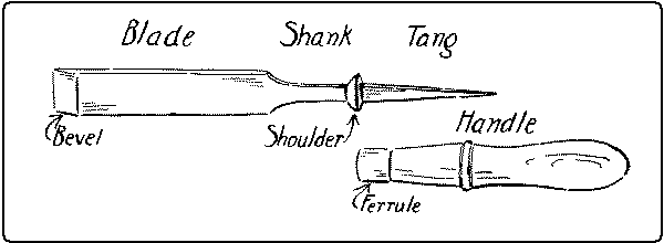
In the modern chisel, all the grinding is done on one side. This constitutes the essential feature of the chisel, namely, that the back of the blade is kept perfectly flat and the face is ground to a bevel. Blades vary in width from 1⁄16 inch to 2 inches. Next to the blade on the end of which is the cutting edge, is the shank, Fig. 65. Next, as in socketed chisels, there is the socket to receive the handle, or, in tanged chisels, a shoulder and four-sided tang which is driven into the handle, which is bound at its lower end by a ferrule. The handle is usually made of apple wood.
The most familiar form is the firmer-chisel, Fig. 65, which is said to get its name from the fact that it is firmer or stiffer than the paring-chisel. (See below.) The firmer-chisel is a general utility tool, being suited for hand pressure or mallet pounding, for paring or for light mortising.
Different varieties of chisels are named; (1) according to their uses; as paring-chisels, framing-chisels, mortise-chisels, carving-chisels, turning-chisels, etc.
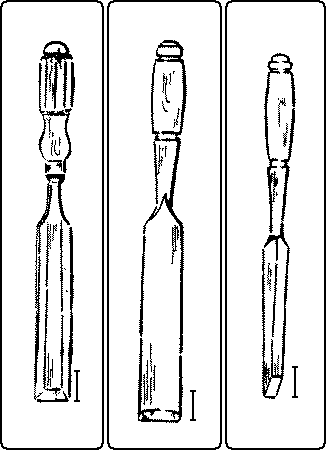
The paring-chisel, Fig. 66, has a handle specially shaped to give control over its movements, and a long thin blade, which in the best form is beveled on the two edges to facilitate grooving. [page 55] It is intended only for steady pressure with the hand and not for use with a mallet.
The framing-chisel, Fig. 67, is thick and heavy and was formerly much used in house framing. It is usually made with the handle fitting into a socket on the shank, in order to withstand the shock of heavy blows from the mallet.
The mortise-chisel, Fig. 68, is made abnormally thick to give the stiffness necessary for levering the waste out of mortises.
(2) Chisels are also named according to their shapes: as, skew-chisels, corner-chisels, round-nosed chisels, etc.
The angle of the bevel of a chisel is determined by the kind of wood for which it is most used, hard wood requiring a wider angle than soft wood, in. For order to support the edge ordinary work, the bevel is correctly ground to an angle of about 20°. The chisel is a necessary tool in making almost every kind of joint. It may almost be said that one mark of a good workman is his preference for the chisel. Indeed an excellent motto for the woodworker is: "When in doubt, use a chisel".
In general, there are two uses for the chisel (1), when it is driven by a push with the hand, as in paring, and (2), when it is driven by blows of a mallet, as in digging mortises.
In relation to the grain of the wood, it is used in three directions: (1) longitudinally, that is with the grain, called paring; (2) laterally, across the surface, called cutting sidewise; (3) transversely, that is across the end, called cutting end-wood.
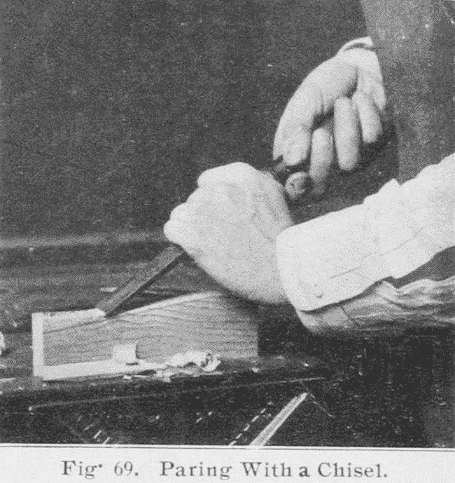
1. Paring. To remove shavings rapidly, the chisel is held flat side up, the handle grasped by the right hand, with the thumb pointing toward the shank, and the blade held in the left hand, as in Fig. 69. Held in this way great control can be exerted and much force applied. For paring the surface as flat and smooth as possible, the chisel should be reversed, that is, held so that the flat side will [page 56] act as a guide. Held in this way the chisel has no equal for paring except the plane. Paring with the chisel is the method used in cutting stop chamfers. (See p. 185, Chapter VIII.) By holding the cutting edge obliquely to the direction of the grain and of the cut, the effective "sliding cut" is obtained, Fig. 64.
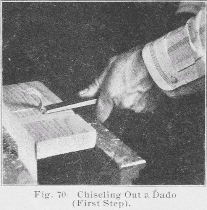
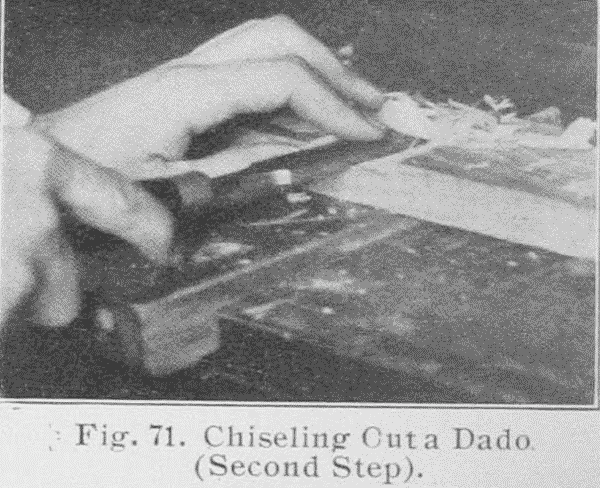
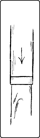
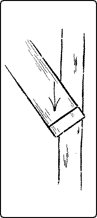
2. In sidewise chiseling the chisel is held in the same manner as in paring. A typical form of sidewise chiseling is the cutting out of a dado, Fig. 70. The work may be placed on the bench-hook or held in the vise with the side up from which the groove is to be cut. The chisel is pushed directly across the grain, the blade being somewhat inclined to the upper surface so as to cut off a corner next the saw kerf. After a few cuts thus made with the chisel inclined alternately both ways, the ridge thus formed is taken off, Fig. 71. In this way the surface is lowered to the required depth. If more force be required, the palm of the hand may be used as a mallet.
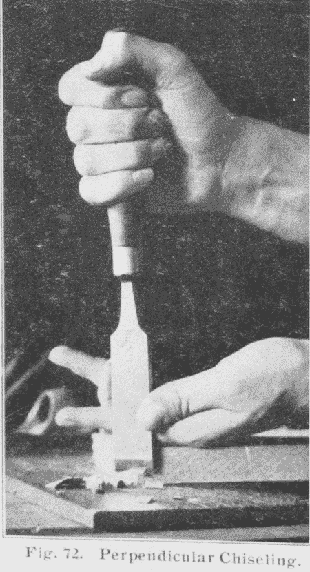
3. In chiseling end-wood, it is well, if possible, to rest the piece to be trimmed flat on the cutting board or on a piece of waste wood. Work done in this way is often called perpendicular chiseling, Fig.72. The handle is grasped in the right hand, [page 57] thumb up, while the blade of the chisel passes between the thumb and first finger of the left hand, the back of which rests on the work and holds it in place. As the right hand pushes the chisel downwards the thumb and first finger of the left hand control its motion. When chiseling it is well to stand so as to look along the line being cut. Incline the chisel toward you, and use the near part of the cutting edge for a guide and the farther corner for cutting, pushing the handle both down and forward at the same time, Fig. 73. Or, by pushing the chisel sidewise with the thumb of the left hand at the same time that the right hand pushes it downward, the effective sliding cut is obtained.
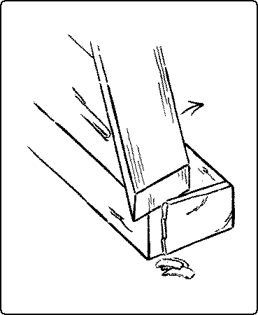
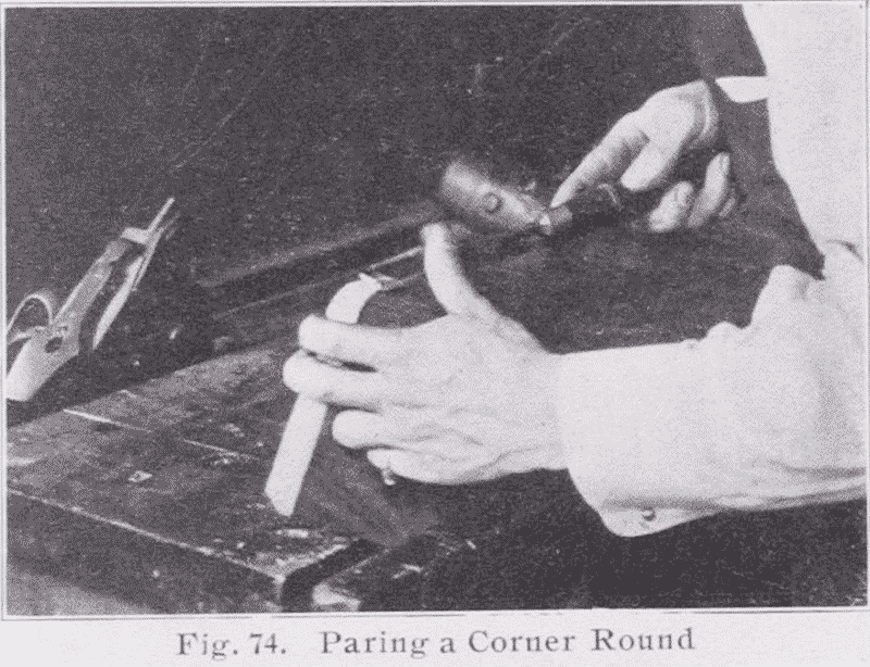
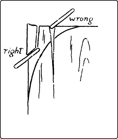
End chiseling requires considerable force and therefore only thin shavings should be cut off at a time. Or the mallet may be used with caution. In order to leave a smooth surface the chisel must be very sharp. Even then the lower arris (corner) is likely to be splintered off. This can be prevented by clamping the work down tight with a handscrew to a perfectly smooth cutting board. It is often advisable however, to set the piece upright in the vise and pare off thin shavings horizontally, Fig. 74. In rounding a corner, both this and perpendicular chiseling are common methods. In both cases care should be taken to cut from the side toward the end and not into the grain, lest the piece split, Fig. 75. In horizontal end paring, [page 58] Fig. 74, in order to prevent splintering, it is well to trim down the arrises diagonally to the line and then to reduce the rest of the end surface.
In all hand chiseling, it is a wise precaution not to try to cut out much material at each stroke but to work back gradually to the line.
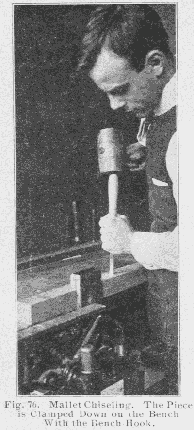
A typical form of mallet chiseling is the digging of a mortise, Fig. 76. (See also p. 56.) The chisel is held perpendicular in the left hand, while the right hand drives blows with the mallet. The hammer should never be used. (See mallet, p. 96.) By rocking the chisel and at the same time giving it a twisting motion while the edge is kept on the wood, the edge can be stepped to the exact place desired. Care should be taken to work back to the lines gradually, to cut only part way thru from each side (in the case of a thru mortise-and-tenon), and to keep the cut faces perpendicular to the surfaces.
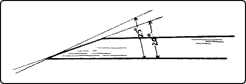
In sharpening a chisel it is of first importance that the back be kept perfectly flat. The bevel is first ground on the grindstone to an angle of about 20° and great care should be taken to keep the edge straight and at right angles to the sides of the blade.
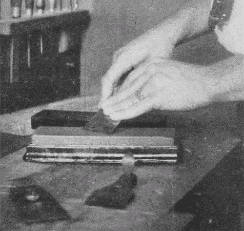
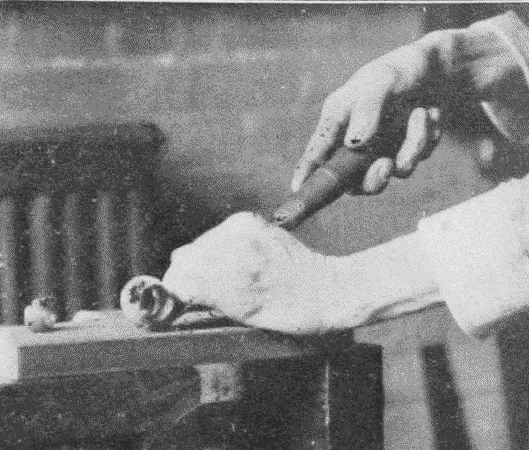
After grinding it is necessary to whet the chisel and other edged tools. (See also under oilstones, p. 121.) First see that there is plenty of oil on the stone. If an iron box be used, Fig. 77, the oil is obtained simply by turning the stone [page 59] over, for it rests on a pad of felt which is kept wet with kerosene.
Place the beveled edge flat on the stone, feeling to see if it does lie flat, then tip up the chisel and rub it at an angle slightly more obtuse than that which it was ground, Fig. 78. The more nearly the chisel can be whetted at the angle at which it was ground the better. In rubbing, use as much of the stone as possible, so as to wear it down evenly. The motion may be back and forth or spiral, but in either case it should be steady and not rocking. This whetting turns a light wire edge over on the flat side. In order to remove this wire edge, the back of the chisel, that is, the straight, unbeveled side, is held perfectly flat on the whetstone and rubbed, then it is turned over and the bevel rubbed again on the stone. It is necessary to reverse the chisel in this way a number of times, in order to remove the wire edge, but the chisel should never be tipped so as to put any bevel at all on its flat side. Finally, the edge is touched up (stropped) by being drawn over a piece of leather a few times, first on one side, then on the other, still continuing to hold the chisel so as to keep the bevel perfect.
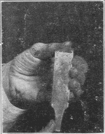
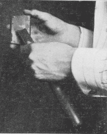
To test the sharpness of a whetted edge, draw the tip of the finger or thumb lightly along it, Fig. 79. If the edge be dull, it will feel smooth: if it be sharp, and if care be taken, it will score the skin a little, not enough to cut thru, but just enough to be felt.
The gouge is a form of chisel, the blade of which is concave, and hence the edge curved. When the bevel is on the outside, the common form, it is called an outside bevel gouge or simply a "gouge," Fig. 80; if the bevel is on the inside, it is called an inside bevel, or inside ground, or scribing-gouge, or paring-gouge, Fig. 81.3
Footnote 3: Another confusing nomenclature (Goss) gives the name "inside gouges" to those with the cutting edge on the inside, and "outside gouges" to those with the cutting edge on the outside.
[page 60]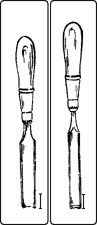
|
Fig. 80. Firmer-Gouge Outside Bevel. |
Fig. 81. Inside bevel Gouge. |
Carving tools are, properly speaking, all chisels, and are of different shapes for facility in carving.
For ordinary gouging, Fig. 82, the blade is gripped firmly by the left hand with the knuckles up, so that a strong control can be exerted over it. The gouge is manipulated in much the same way as the chisel, and like the chisel it is used longitudinally, laterally, and transversely.
In working with the grain, by twisting the blade on its axis as it moves forward, delicate paring cuts may be made. This is particularly necessary in working cross-grained wood, and is a good illustration of the advantage of the sliding cut.
In gouging out broad surfaces like trays or saddle seats it will be found of great advantage to work laterally, that is across the surface, especially in even grained woods as sweet gum. The tool is not so likely to slip off and run in as when working with the grain.
The gouge that is commonly used for cutting concave outlines on end grain, is the inside bevel gouge. Like the chisel in cutting convex outlines, it is pushed or driven perpendicularly thru the wood laid flat on a cutting board on the bench, as in perpendicular chiseling, Fig. 72. p. 56.
In sharpening an outside bevel gouge, the main bevel is obtained on the grindstone, care being taken to keep the gouge rocking on its axis, so as to get an even curve. It is then whetted on the flat side of a slipstone, Fig. 83, the bevel already obtained on the grindstone being made slightly more obtuse at the edge. A good method is to rock the gouge on its axis with the left hand, while the slipstone held in the right hand is rubbed back and forth on the edge. Then the concave side is rubbed on the round edge of [page 61] the slipstone, care being taken to avoid putting a bevel on it. Inside bevel gouges need to be ground on a carborundum or other revolving stone having a round edge. The outfit of the agacite grinder, (Fig. 224, p. 120), contains one of these stones. The whetting, of course, is the reverse of that on the outside bevel gouge.
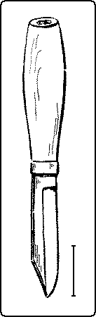
The knife differs from the chisel in two respects, (1) the edge is along the side instead of the end, and (2) it has a two-beveled edge. Knives are sometimes made with one side flat for certain kinds of paring work, but these are uncommon. The two-beveled edge is an advantage to the worker in enabling him to cut into the wood at any angle, but it is a disadvantage in that it is incapable of making flat surfaces. The knife is particularly valuable in woodwork for scoring and for certain emergencies. The sloyd knife, Fig. 84, is a tool likely to be misused in the hands of small children, but when sharp and in strong hands, has many valuable uses. A convenient size has a 2½ inch blade. When grinding and whetting a knife, the fact that both sides are beveled alike should be kept in mind.
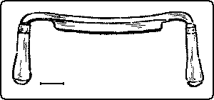
The draw-knife, Fig. 85, is ground like a chisel, with the bevel only on one side, but the edge is along the side like a knife. Instead [page 62] of being pushed into the wood, like a chisel, it is drawn into it by the handles which project in advance of the cutting edge. The handles are sometimes made to fold over the edge, and thus protect it when not in use. The size is indicated by the length of the cutting edge. It is particularly useful in reducing narrow surfaces and in slicing off large pieces, but it is liable to split rather than cut the wood.
The object of the saw is to cut thru a piece of material along a determined line. Its efficiency depends upon (1) the narrowness of the saw cut or "kerf," and (2) upon the force required to drive it thru the material. The thinner the blade, the less material will be cut out and wasted, and the less force will have to be applied. In order to have the saw as thin as possible, almost all the people of the world, except the Anglo Saxons, have saws that cut when they are pulled toward the worker. The blade is in tension while cutting and in compression only when being returned for a new cut. German carpenters use a saw like our turning-saw. English and Americans have developed the saw on the opposite principle, namely, that it should cut on the pushing stroke. As a matter of fact, the crosscut-saw cuts somewhat on the back stroke. The pushing stroke necessitates a thickening of the blade sufficient to prevent buckling,—a not uncommon occurrence in the bands of a novice, in spite of this thickening. But tho this requires more force, and involves more waste, there are the compensations that the arm can exert more pressure in pushing than in pulling, especially when the worker stands upright or stoops over his work, and the stiffer wide blade acts as a guide to the sawyer. Each method has its advantages. Whatever may be true of hand-saws, in machine-saws the tension method, as illustrated by the gang-saw and the band-saw, is steadily displacing the compression method utilized in the circular-saw. Many kinds of work, however, can be done only on the circular-saw.
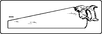
In order to diminish the disadvantages of the thrusting stroke, the modern hand-saw, Fig. 86, has been gradually improved as the result of much experience and thought. The outline of the blade is tapered in width from handle to point; it is thicker also at the [page 63] heel (the handle end) than at the point; its thickness also tapers from the teeth to the back. All these tapers gives stiffness where it is most needed. It is made wide for the sake of giving steadiness in sawing. The fact that it is thinner at the back than along the teeth gives it clearance in passing back and forth in the kerf, but the friction is still great, especially in sawing soft or damp wood. To avoid this binding still further, the teeth are "set" alternately one to one side and the next to the other, and so on.
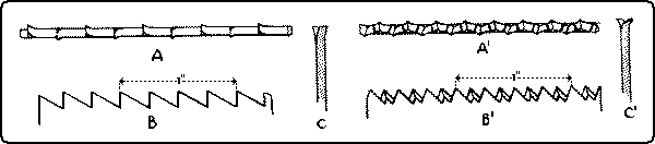
The size of saws is indicated by the length of the blade in inches. The coarseness of the tooth is indicated by the number of "points" to the inch. "Points" should not be confused with teeth as there is always one more point per inch than there are teeth. For example, a five point rip-saw has five points to the inch but only four full teeth, Fig. 87. Rip-saws run from 4 to 7 points per inch; crosscut-saws from 6 to 12 points per inch.
In general, saws are of two kinds, rip-saws and crosscut-saws.
The rip-saw, Fig. 87, may be thought of as a series of chisels set in two parallel rows which overlap each other, for each tooth is filed to a sharp edge which, at each stroke, chisels off a small particle from the end of the wood fibers.
The shape of the teeth is the result of experience in uniting a number of factors: as, strength of the individual tooth, the acuteness of the cutting angle, and the ease of sharpening. The steel of a saw is softer than that of a chisel, in order that it may be filed and set. Hence it is weaker and the edge cannot be so acute. A typical form of tooth is shown in Fig. 87, in which A is an edge view, B the side view, and C a cross section. The angle of each tooth covers 60°, one side, the "face", being at right angles to the line of the teeth. The cutting edge runs at right angles to the sides of the blade.
This arrangement works with entire success along the grain, but if a rip-saw is used to cut across the grain, since there is no provision [page 64] for cutting thru the fibers, each tooth catches in them and tears them out, thus leaving a rough and jagged surface.
In the crosscut-saw, therefore, the teeth are filed to points, and the cutting edge is on the forward side of each alternate tooth. In Fig. 87. A' is the edge view, B' is the side view and C' is a cross-section. In a properly filed crosscut-saw a needle will slide between these two rows of teeth from one end of the saw to the other.
In action the points, especially their forward edges, cut or score the fibres of wood, and then the triangular elevation of wood left between the two rows of points is crumbled off by friction as the saw passes through. Thus it drops farther and farther into the cut. A crosscut-saw may be thought of as a series of knife points, arranged in two parallel rows. Ordinarily the angle of the "face" of each tooth with the line of the teeth is about 65°, and slightly steeper than the back of the tooth. The angle of the cutting edge of each tooth may be filed more acute when the saw is to be used for soft wood only.
A crosscut-saw when used to rip a board, works slowly, for there is no chisel action to cut out the fibres between the points, but the cut, tho slow, is smooth. In cutting diagonally across a piece of wood, especially soft wood, a rip-saw cuts faster, but a crosscut, smoother. In ripping a board, allowance should always be made for planing to the line afterward. In starting a cut with the rip-saw, the weight of the saw should be borne by the right hand so that the teeth may [page 65] pass over the edge of the wood as lightly as possible. The left thumb acts as a guide. If the saw be handled thus, and the angle with the board be quite acute, it is not necessary to start with a back stroke. When the kerf is well started, the whole weight of the saw may be applied. An easy light stroke is better than a furious one. The line should be followed carefully, but if the saw runs from the line it may be brought back by taking short strokes near the point of the saw and twisting the blade slightly in the desired direction. If the saw binds and buckles because of the springing together of the wood, the kerf may be wedged open with a screwdriver or a bit of waste wood. A drop of oil rubbed across each side of the saw will make it work more easily.
Care should be taken in finishing a cut to hold up firmly the part of the wood which is being sawn off so that it will not split off or splinter.
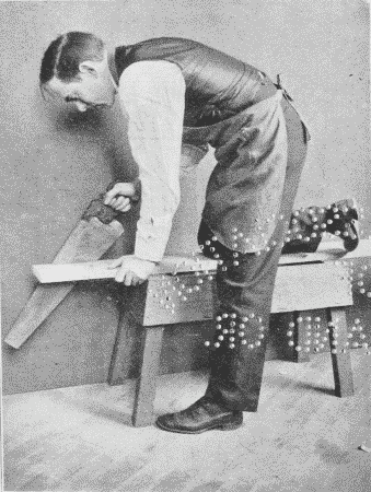
Sawing may be done either on a saw-horse, Fig. 88, or at a bench. For big, rough work, the former is the common way, the worker holding the material in place with one knee, because this method enables him to exert his greatest strength. A convenient way for rip-sawing a small piece of wood is to insert it in the vise, Fig. 89, with the broad side of the board parallel to the vise screw, and the board inclined away from the worker who stands upright. The start is easy, the sawdust does not cover the line, and the board is not in danger of splitting. The board, however, has to be reversed after it is sawn part way thru, in order to finish the saw cut.
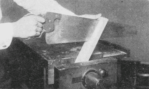
The back-saw or tenon-saw, Fig. 90. is a fine crosscut-saw, with a rib of steel along the back, which gives to it its name. Since it is intended for small accurate work, the teeth have little or no set.
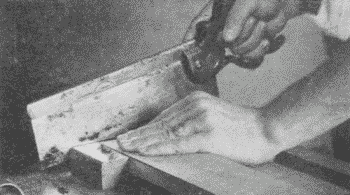
In sawing, the wood may be held either in the vise or on the bench-hook. To help start the saw and at the same time to keep the edges of the cut sharp, it is well to make a little groove [page 66] with the knife, on the waste side of the line to be followed, cutting the side of the groove next to the line at right angles to the surface. The saw drops directly into this groove, Fig. 91. In starting the saw cut, the saw should be guided by holding the thumb of the left hand against the side of the saw just above the teeth. Until the kerf is well started, the saw should be held so that the teeth just touch the wood. It is better not to attempt to start the saw level, i. e., with the teeth resting clear across the wood, but the handle should be raised so that the start is made only at the farther edge of the wood. Then as the saw is gradually lowered, the kerf will extend quite across the wood, Fig. 92. When the back-saw is used for ripping, the wood is held in the vise, end up. Begin sawing as in crosscutting, that is, at the farther corner with the handle end of the saw up, and gradually drop the handle. Watch the lines on both the front and back sides, and if necessary, reverse the piece to follow them.
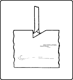
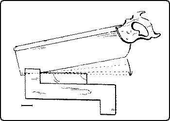
The dovetail-saw, Fig. 93, is a small back-saw for delicate work.
The compass-saw, Fig. 94, is narrow, pointed, thick, to prevent [page 67] buckling, and with a wide set to the teeth, to help in following the curves. The teeth are a cross between the rip and crosscut teeth. It is used in sawing curves.
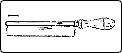
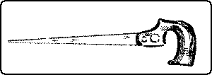
The turning-saw, Fig. 95, is a narrow saw, set in a frame, which stretches the saw tight, so that it works as a tension saw (cf. p. 62). The best frames are made so that the handles which hold the blade can revolve in the frame. The turning-saw is used chiefly for cutting curves. A 14 inch blade, 3⁄16 of an inch wide is a good size for ordinary use. The teeth are like those of a rip-saw, so that they are quite likely to tear the wood in cutting across the grain. Allowance should be made for this and the surplus removed with a spokeshave. The turning-saw may be used to cut on either the pulling or the pushing stroke, with the teeth pointed either toward or away from the worker. The pulling cut is generally better, as it puts less strain on the frame than the pushing cut. Both hands should grasp the frame as near the end of the blade as possible, Fig. 95. Turns are made by revolving the frame on the blade as an axis, which should always be kept at right angles to the surface of the board. Care should be taken not to twist the blade.
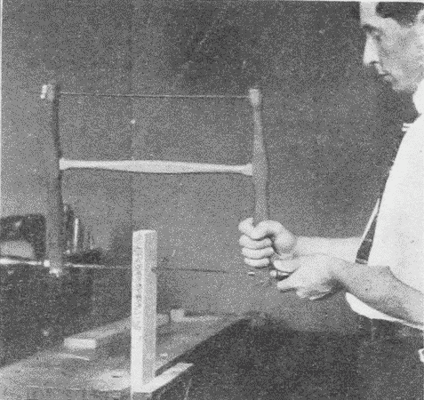
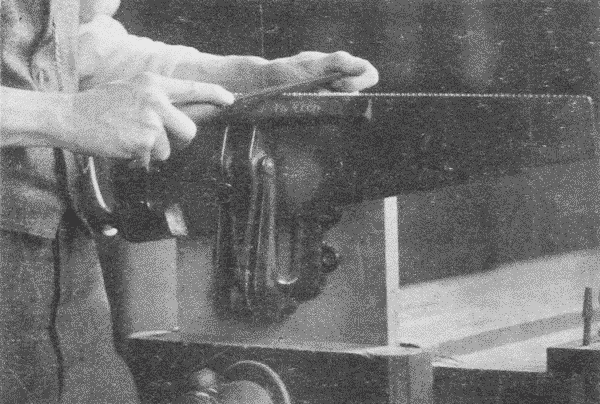
To file and set a saw, the saw is first fastened in [page 68] the saw-vise, Fig. 96, with the teeth up. It is then top-jointed by running a flat file or a saw-jointer, Fig. 97, back and forth lengthwise along the tops of the teeth to bring them to a level. After jointing the saw should be set. For this purpose a saw-set. Fig. 98, is necessary. Every alternate tooth is bent in the direction of its set by the plunger in the instrument pushing against the anvil, which is an adjustable eccentric disc. After the saw is set, it is filed. This is done with a triangular file, Fig. 144, p. 90, which is held in the right hand and its point in the thumb and fingers of the left. Pressure is applied only on the forward stroke, which should be long and even, the file being raised above the tooth on the return stroke. The file should cut in the direction of the set, that is, the teeth having the set away from the worker are filed first. Every alternate tooth, 1st. 3d, 5th, etc., is filed, and then the saw is reversed and the other set, the 2nd, 4th, 6th, etc., is filed.
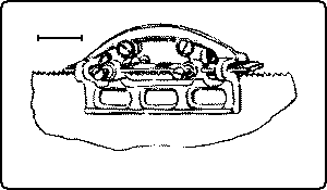
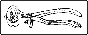
In filing a rip-saw the file should move exactly perpendicularly to the plane of the saw blade, that is, directly across the teeth. The filing is done on the back of the teeth, the file just touching the face of the next one. The filing is continued, with one, two, or three strokes, for each tooth, as the case may require, or just until each tooth is sharp.
In filing a crosscut-saw, the file is held pointing upward and toward the point of the saw. The file should cut in the direction of the set. The angle of the cutting edge is determined by the horizontal inclination of the file to the blade; the angle of the point is determined by the perpendicular inclination of the file to the blade. Finally the sides of the teeth are rubbed lightly with a slipstone to remove the wire edge. It should always be remembered that a saw is an edge tool, and its edges are as liable to injury as any edges.
[page 69]The plane is a modified chisel. The chief difference in action between a chisel and a plane in paring is this: the back of the chisel lies close down on the surface of the wood that is cut, and acts as a guide; whereas, in the plane, the cutter is elevated at an angle away from the surface of the wood, and only its cutting edge touches the wood, and it is held and guided mechanically by the plane mechanism. In other words, a plane is a chisel firmly held in a device which raises the cutter at an angle from the work, regulates the depth of the cut, and favors the cutting rather than the splitting action. An illustration of a chisel converted into a plane is the adjustable chisel-gage, Fig. 99.
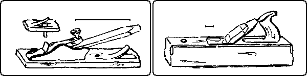
The plane has developed as follows: it was first a chisel held in a block of wood. This is all that oriental planes are now, simply a sharpened wedge driven into a block of wood. When the hole works too loose, the Japanese carpenter inserts a piece of paper to tighten it, or he makes a new block. The first improvement was the addition of a wooden wedge to hold in place the "plane-iron", as the cutter was formerly called. In this form, the cutter or plane-iron, tho still [page 70] wedge-shaped, was reversed, being made heavier at the cutting edge in order to facilitate fastening it in the wooden plane-stock by means of the wooden wedge. Then a handle was added for convenience. Then came the cap, the object of which is to break back the shaving and thus weaken it as soon as possible after it is cut. Until a few years ago, this was all that there was in a plane, and such planes are still common, Fig. 100. Finally there appeared the iron plane, Fig. 101, with it various mechanical adjustments. The following are the parts of the Bailey iron plane:4
Footnote 4: The numbers and names in italics are those given in Stanley's Catalog, No. 34. Some of these names, as "plane-iron," are survivals from the days of the wooden plane and are obviously unsuitable now.
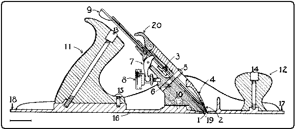
1. Cutter, or bit, or blade, or plane-iron.
2. Cap, or plane-iron cap, or curling iron.
3. Cutter screw, or plane-iron Screw.
4. Clamp, or lever cap, or wedge.
5. Clamp screw, or cap screw.
6. Frog.
7. Y Adjustment.
8. Brass set screw, or brass adjusting nut.
9. Lever (for lateral adjustment).
10. Frog screw.
11. Handle.
12. Knob.
13. Handle bolt and nut.
14. Knob screw, or Knob bolt and nut.
15. Handle screw.
16. Bottom, or sole.
17. Toe.
18. Heel.
19. Throat.
20. Thumb piece, or clamp lever, or cam.
There are various principles involved in the action of the plane. The effect of the flat sole is to regulate the cut of the cutter. If the surface be uneven, the cutter will not cut at all, or but little, in passing over low places, since the toe and heel of the sole will then be resting on higher places; but when the cutter reaches a high place a shaving will be taken off. Hence it follows that the longer the plane, the straighter will be the surface produced. The length of the plane used is determined by the length of the wood to be planed, and the degree of straightness desired.
[page 71]The part of the sole directly in front of the cutter presses firmly down on the wood and so prevents the shaving from splitting far in advance of the edge. It follows that the narrowness of the mouth in a plane is an important factor in the production of smooth surfaces. This can be regulated by adjusting the toe in the block-plane, and by moving the frog in the jack- and smooth-planes.
A recent improvement in jack-, smooth-, and fore-planes consists of an adjustable frog, by means of which the throat can be narrowed or widened at will by means of a set-screw in the rear of the frog without removing the clamp and cutter. It is made by Sargent and Company. The Stanley "Bed Rock" plane has a similar but less convenient device.
The splitting of the wood in advance of the edge is also prevented by the breaking of the shaving as it hits against the cutter or its cap. Hence the advantage of bending up and breaking or partly breaking the shaving as soon as possible after it is cut. This shows why the cap is set close to the edge of the cutter. Another reason is that it thereby stiffens the cutter and prevents "chattering." If a thick shaving be desired the cap has to be set farther back. In a smooth-plane 1⁄32 inch is enough, in a jack-plane ⅛ inch is often desirable. The following are the planes in common use:
The jack-plane, Fig. 102, 14" to 15" long, is the one used where a considerable amount of material is to be taken off to bring a piece of wood to size, and therefore the outline of the cutting edge instead of being straight is slightly curved or "crowned" so that in planing the surface of a board it makes a series of shallow grooves, the ridges of which must afterward be smoothed off by another plane. Also for beginners whose hands are not strong it is sometimes wise to grind the cutter with some "crown", in order to take off narrow shavings, which require less strength. For school use, where the jack-plane is used for all purposes, the cutter [page 72] is usually ground almost straight and only the corners rounded as in the smooth-plane and the fore-plane.5
Footnote 5: In whetting a plane-bit, a slight crown may be given it by rubbing a bit harder at the ends of the edge than in the middle. Strop in the same way as a chisel (p. 59).
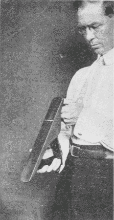
The fore-plane, 22" to 26" long, and the jointer, 28" to 30" long, are large planes, similar to the jack-plane, except that the cutting edge is straight. They are used for straightening and smoothing long pieces.
The smooth-plane, 5½" to 10" long, is a short plane, similar to the jack-plane, except that the cutting edge is straight. It is used for smoothing.
These four planes, the jack-plane, the fore-plane, the jointer, and the smooth-plane, are essentially alike, and directions for the use of one apply to all.
There are two chief adjustments in the Bailey iron plane: the brass set-screw, see 8 in Fig. 101, which regulates the depth of the cut, and the lever, 9, which moves the cutter sidewise so that it may be made to cut evenly. The skilful worker keeps constant watch of these adjustments. It is well to form the habit of always sighting along the sole before beginning to plane, in order to see that the cutter projects properly, Fig. 102. It is a common mistake among beginners to let the cutter project too far.
It is important to know what is the best order of procedure in planing up a board. There are often reasons for omitting the planing up of one or more surfaces, but it is wise to form the habit of following a regular order, and the following is suggested as a good one:
1. Working face. Plane one broad side flat and smooth. Finish with the plane set to cut line shavings. Test with try-square. Mark this face with a distinct pencil mark, A, Fig. 103.
2. Working edge. Plane one narrow side straight and square with the working face. Test with try-square, pressing the block of the try-square against the working face. Mark the working edge with two distinct pencil marks, B, Fig. 103.
3. End. First mark the width on the working face with the marking-gage, C, 1-2, Fig. 103. Chisel off the corner, a, of the piece outside this gaged line. True and smooth this end with the plane, making it square with both working face and working edge, D, 2, 3, 4, Fig. 103.
4. Length. Measure the length from the finished end, D, 2-3-4, score across the working face, D, 5-6, and working edge, D, 6-7, [page 73] using a sharp knife point and the try-square. Saw just outside this line, D, 5-6-7, with the back-saw, cut off the narrow corner, D, b, beyond the gaged line and plane true, E, Fig. 103.
5. Width. Plane to the center of the gaged line, E, 1-2. Test this edge from the working face, F, Fig. 103.
6. Thickness. Mark the thickness with the marking-gage all around the piece, F, 8-9-10. Plane to the center of the gaged line, G, Fig. 103. Test this face for flatness.
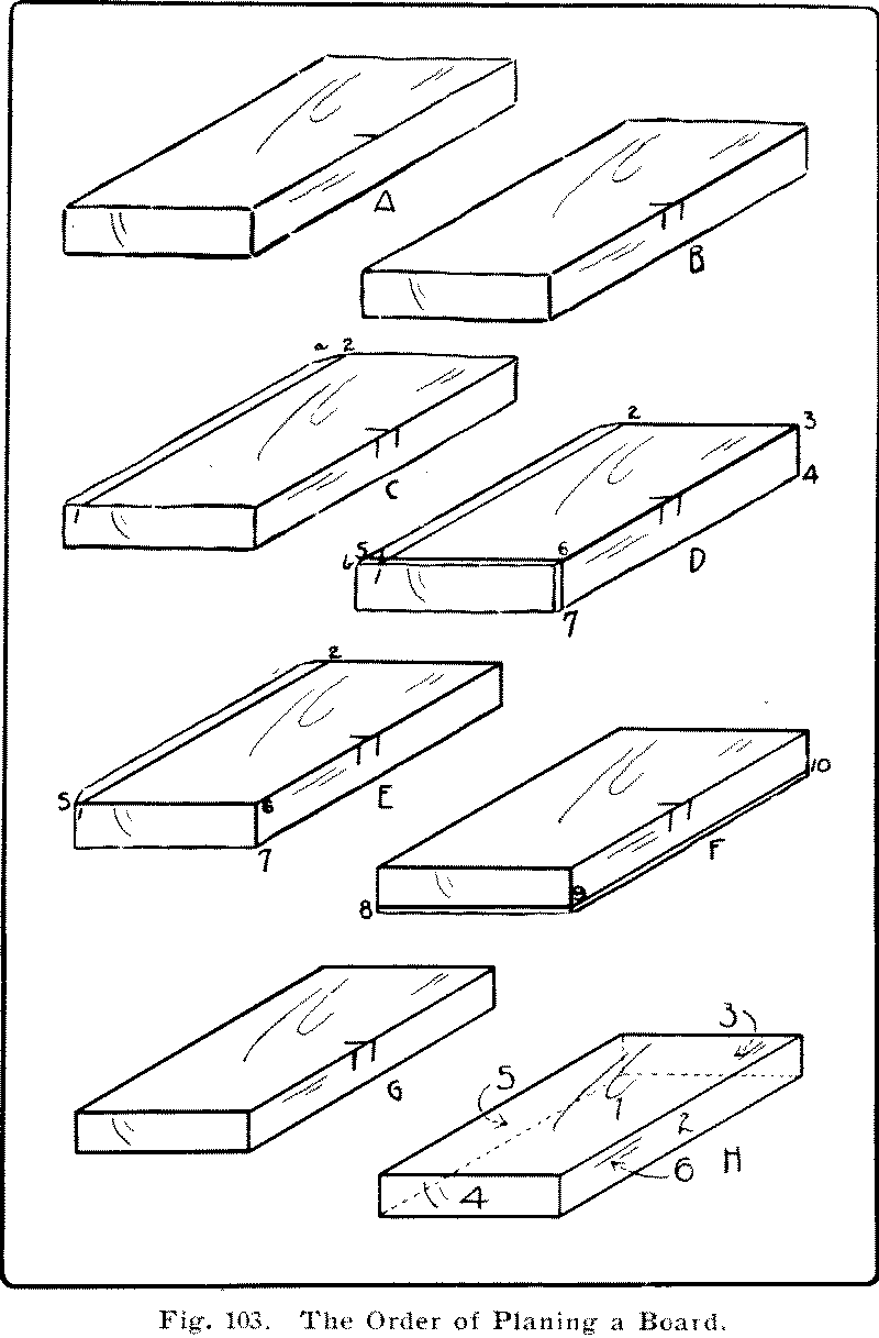
In a word, the order to be followed is graphically represented in H, Fig. 103. The surfaces are numbered consecutively in the order in which they are to be planed.
The advantages of this order are these: by planing the working face first, a broad surface is secured to which the others may be made true. By planing the ends before the width is planed, the danger of splitting off fragments can be avoided by chiseling the corner of the unfinished edges, C, a, and D, b, Fig. 103, into a buttress. By planing the ends and the width before the thickness is planed, a dressed face is secured all around for gaging the thickness. In following this order all measurements and markings are made on a dressed face.
If there be any "wind" or twist in the board, this should be discovered first of all. This may be done roughly by sighting across the broad side of the board, Fig. 104, and more accurately by the use of "winding sticks," see Fig. 205, p. 113. Or the surface may be tested with the plane itself by tilting the plane on its long corner edge, and resting it on the board, while the worker looks between the board and the plane toward the light. It is evident that the plane must be turned in various directions to test for wind, and that a board only as long or as wide as the plane is long can be tested in this way. The try-square or any straight edge may be used for the same purpose, Fig. 105. If there be any wind in the board, this should at once be taken out of one face by planing down the high corners.
 Fig. 104. Sighting for Wind. |
 Fig. 105. Testing from Edge to Edge. |
In starting to plane, the worker should bear down on the knob at the front end of the plane. When the plane is well on the board, he should bear down equally on both [page 75] knob and handle, and as the plane begins to pass off the board he should put all the pressure on the handle end, Fig. 106. By taking pains thus, a convex surface will be avoided, the making of which is a common error of beginners. On the return stroke, the plane should be lifted or tilted so that the cutting edge will not be dulled by rubbing on the wood. This is especially important on rough and dirty boards, as it saves the cutting edge, and in fine work, as it saves the work. If the plane tear the wood instead of cutting it smooth, as it should, it is because the planing is "against the grain". This can often be avoided by noticing the direction of the grain before beginning to plane. But even if it be not noted beforehand, a stroke or two will show the roughness. In such a case, it is necessary simply to turn the wood around.
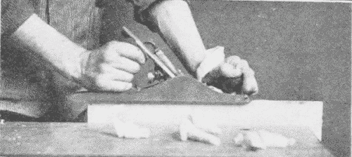
The accuracy of the work as it progresses should frequently be tested, and the eye should constantly be trained so that it can more and more be depended upon to detect inaccuracy, Fig. 107. As each surface is trued, it should be carefully smoothed with the cutter set to cut fine shavings.
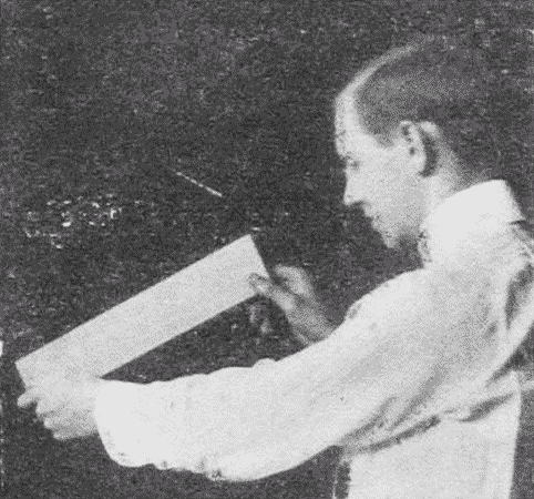
In planing a very cross-grained piece of wood, there are several methods to use for securing a smooth surface. The frog of the plane should be moved forward so that the throat in the front of the cutter is a mere slit. In the ordinary plane it is necessary to remove the cutter in order to reset the frog, but in the Sargent plane and the Stanley "bed rock" plane, it can be set by a set-screw at the rear of the frog. Next, the cap should be set so that the cutter projects but very little beyond it, or, in technical language, the cutter should be set "fine." A sliding cut, see p. 53, should be taken with the plane, and sometimes it may be necessary to move the plane nearly at right angles to the general direction [page 76] of the grain. By these means even refractory pieces of wood can be well smoothed. See also scrapers, p. 91.
The choking of a plane is the stoppage of the throat by shavings. It may be due simply to the fact that the cutter is dull or that it projects too far below the sole of the plane. In a wooden plane choking is sometimes due to the crowding of shavings under some part of the wedge. When the adjustable frog in a modern plane is improperly placed choking may result. The frog should be far enough forward so that the cutter rests squarely upon it.
Choking may, and most commonly does, take place because the cap does not fit down tight on the cutter. This happens if the cap be nicked or uneven. In consequence, minute shavings are driven between these two irons and choking soon results. The remedy is to sharpen the cap, so that its edge makes a close fit with the cutter. The fit may be made still tighter by rubbing with a screwdriver the edge of the cap down on the cutter after it is screwed in place.
In no tool is it more important to keep the cutter sharp than in the plane. To remove the cutter, in order to sharpen it, first loosen the clamp lever and remove the clamp. Carefully remove the cap and cutter taking pains not to let the edge hit any part of the plane, then using the clamp as a screwdriver, loosen the cap-screw and slide the cap back along the slot in the cutter, where it can be held fast by a turn of the cap-screw. The edge is now free and can readily be whetted. When the cap needs to be entirely removed, for instance, for grinding, after it has been slid along the cutter slot, as before, it is turned at right angles to the cutter, and then slid down the slot until the cap-screw unbuttons from the cutter. The object in sliding the cap up the slot before turning it, is to prevent the danger of injuring the edge. Some caps are now made with the buttonhole at the upper end of the slot.
After sharpening, (see under sharpening, p. 117.) the order is reversed for replacing the cutter. The cap is set at right angles to the cutter, the cap-screw dropped into the slot, the cap is slid up the slot, and turned into line with the cutter, and then slid down the slot till the edge of the cap comes quite near the edge of the cutter. Then the two are held firmly together with the left hand until the cap screw is turned tight.
In replacing the cutter and cap in the plane, care should be taken not to injure the edge and to see that the Y adjustment lever fits [page 77] into the little slot in the cap; then finally the lever is thrown down tight. Then, by turning the plane sole upward and glancing down it, the proper adjustments with the brass set-screw and lateral adjustment lever are made. When the plane is not being used, it should rest either on a pillow (a little strip of wood in the bench trough), or on its side. In no case should it be dropped sole down flat on the bench.
The block-plane, Fig. 108, gets its name from the fact that it was first made for planing off the ends of clap-boards, a process called "blocking in".
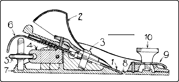
The names of the parts of the Bailey block-plane are6:
1. Cutter or bit or plane-iron.
2. Clamp or lever cup.
3. Cap-screw.
4. Adjusting lever.
5. Adjusting nut.
6. Lateral adjustment.
7. Bottom.
8. Mouth piece.
9. Eccentric plate.
10. Knob.
Footnote 6: See footnote 4, p. 70
The block-plane was devised for use with one hand, as when it is used by carpenters in planing pieces not readily taken to a vise or in planing with a bench-hook. Hence it is made small, 3½" to 8" long, the clamp is rounded so as to act as a handle, and the cutter is lowered to an angle of about 20° to make the plane easy to grasp. The lower angle of the cutter makes it necessary that the bevel be on the upper side. Otherwise, to give clearance, the bevel would have to be made so long and so thin as to be weak. By putting the bevel up, the angle between the wood and the cutter is maintained practically [page 78] as in the smooth-plane. Since the block-plane is intended chiefly for use on end grain, no cap is needed to break the shavings. The adjustable throat makes it possible to cut a very fine shaving. To facilitate the cutting action, several forms of block-planes with a very low angle are now made.
Where both hands are free to hold the plane, the block-plane has no advantage over a smooth-plane, even on end grain. Moreover, the cutter cannot be held so firmly in place as that of a smooth-plane, so that it requires constant adjustment. Hence it is not an easy tool for amateurs to handle. There is considerable lost motion in the adjusting nut, and the set-screw, which acts as a knob, is likely to work loose and be lost. It is hardly to be recommended as a part of the equipment of the individual bench in school shops.
The piece to be planed with the block-plane may be held either in the vise, end up, or on a bench-hook, Fig. 109. In end planing in the vise, in order to avoid splintering the precaution should be taken to trim off a corner on the undressed edge, as directed on page 73, or else the planing must be done from both edges toward the center. The sliding cut is much easier than the straight cut, and hence there is a constant temptation to turn the plane at an angle perhaps at an expense of the flat surface desired.
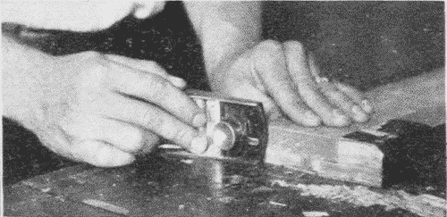
In using the bench-hook the piece to be block-planed is placed with the working edge against the block, with the end to be planed to the right and flush with the edge of the bench-hook, in which position it is held with the left hand. The block-plane, held in the right hand, is placed on its side on the bench facing toward the work. In planing, the left hand holds the work firmly against the block of the bench-hook, pressing it somewhat to the right against the plane. The right hand holds the side of the plane flat on the bench and presses it to the left against the bench-hook and work. Held in this position the plane is pushed forward and back until the end is smoothed. Considerable practice is necessary to handle the block-plane well.
The scrub-plane is a short plane in which the crown of the cutter, Fig. 110, is quite curved. It is used to reduce surfaces rapidly.
[page 79]The scratch-plane, Fig. 111, has a toothed cutter which scratches fine lines along its course. It is used to roughen surfaces of hard wood which are to be glued together, for otherwise the glue would not adhere well. Some tropical woods are so hard that their surfaces can be reduced only by a scratch-plane. It is also useful in preparing the surface of a very cross-grained piece of wood which cannot be planed without chipping. By first scratching it carefully in all directions, it can then be scraped smooth. It is also called a scraper-plane, because accompanying the plane is a scraper which can be inserted in the same stock and inclined at any required angle. This plane-stock prevents the scraper from unduly lowering some portions of the surface. See also veneer-scraper, p. 92.
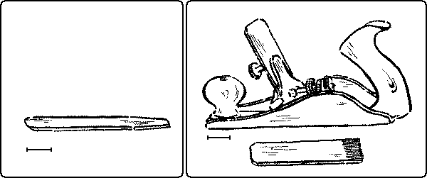
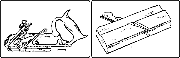
The rabbeting- or rebating-plane, Fig. 112, is designed for use in cutting out a rectangular recess, such as the rabbet on the back of the picture-frames. In line with the right hand corner of the cutter is a removable spur to score the wood so that the shaving which follows [page 80] may be cut out clean and not torn out. With the addition of a guiding fence it is called a filletster. This may be used on either the right or left side. In the form shown in Fig. 112, there is also a depth gage.
In using this plane see that the corner of the cutter is in line with the sole, and that both it and the spur are sharp. Set the fence and the stop at the desired width and depth of the rabbet. At the first stroke the spur will score the width. This and every stroke should be taken as evenly and carefully as if it were the only one. In the effort to keep the fence pressed close to the side of the wood, the tendency is to tilt the plane over. This causes the very opposite effect from that desired, for the spur runs off diagonally, as in Fig. 114.
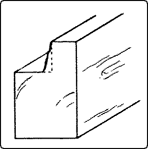
If this happens stop planing at once, clean out the recess properly with a chisel and then proceed.
The dado-plane is much like the rabbeting-plane, except that it is provided with two spurs, one at each side of the cutting edge, to score the wood before cutting.
The molding-plane, Fig. 113, as it name indicates, is for making moldings of various forms; as, quarter-round, half-round, ogee, etc.
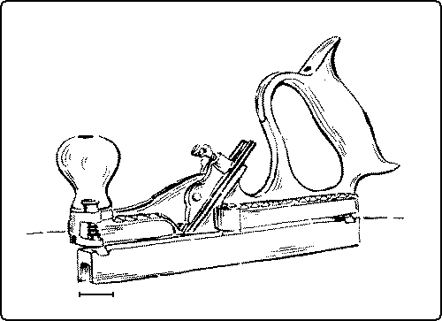
The tonguing-and-grooving-plane, Fig. 115, is for matching boards, i. e. making a tongue in one to fit into a groove in another. See Fig. 269, No. 72, p. 182.
The circular-plane, Fig. 116. has a flexible steel face which can be adjusted to any required arc, convex or concave, so that curved surfaces may be planed.
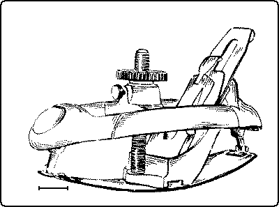
The universal plane, Fig. 117, is a combination of various molding-, rabbeting-, matching- and other planes. It is capable of many adjustments and applications. The principal parts of this plane are: a main stock, A, with two sets of transverse sliding arms, a depth-gage, F, adjusted by a screw, and a slitting cutter with stop, a sliding section, B, with a vertically adjustable bottom, the auxiliary center bottom, C, to be placed when needed in front of the cutter as an extra support or stop. This bottom is adjustable both vertically and laterally. Fences, D and E. For fine work, fence D has a lateral adjustment by means of a thumb-screw. The fences can be used on either side of the plane, and the rosewood guides can be tilted to any desired angle up to 45°, by loosening the screws on the face. Fence E can be reversed for center-beading wide boards. For work thinner than the depth of the fence, the work may overhang the edge of the bench and fence E be removed. An adjustable stop, to be used in beading the edges of matched boards, is inserted on the left side of the sliding section B. A great variety of cutters are supplied, such as: molding, matching, sash, beading, reeding, fluting, hollow, round, plow, rabbet, and filletster. Special shapes can be obtained by order.
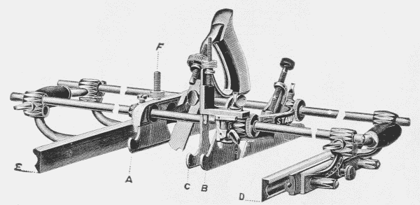
The Use of the Universal Plane. Insert the proper cutter, adjusting it so that the portion of it in line with the main stock, A, will project below the sole the proper distance for cutting.
[page 82]Adjust the bottom of the sliding section, B, so that the lowest portion of the cutter will project the proper distance below it for cutting. Tighten the check nuts on the transverse arms and then tighten the thumb-screws which secure the sliding section to the arms. The sliding section is not always necessary, as in a narrow rabbet or bead.
When an additional support is needed for the cutter, the auxiliary center bottom, C, may be adjusted in front of it. This may also be used as a stop.
Adjust one or both of the fences, D and E, and fasten with the thumb-screws. Adjust the depth-gage, F, at the proper depth.
For a dado remove the fences and set the spurs parallel with the edges of the cutter. Insert the long adjustable stop on the left hand of the sliding section. For slitting, insert the cutter and stop on the right side of the main stock and use either fence for a guide.
For a chamfer, insert the desired cutter, and tilt the rosewood guides on the fences to the required angle. For chamfer beading use in the same manner, and gradually feed the cutter down by means of the adjusting thumb-nut.
There are also a number of planelike tools such as the following:
The spoke-shave, Fig. 118. works on the same principle as a plane, except that the guiding surface is very short. This adapts it to work with curved outlines. It is a sort of regulated draw-shave. It is sometimes made of iron with an adjustable mouth, which is a convenient form for beginners to use, and is easy to sharpen. The pattern-makers spokeshave, Fig. 119, which has a wooden frame, is better suited to more careful work. The method of using the spokeshave is shown in Fig. 120.
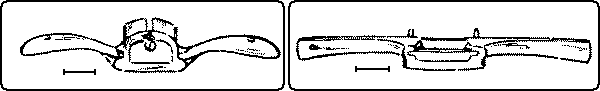
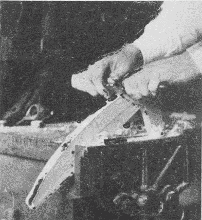
The router-plane, Figs. 121 and 122, is used to lower a certain part of a surface and yet keep it parallel with the surrounding part, and it is particularly useful in cutting panels, dadoes, and grooves. The cutter has to be adjusted for each successive cut. Where there are a number of dadoes to be cut of the same depth, it is wise not to finish them one at a time, but to carry on the cutting of all together, lowering the cutter after each round. In this way all the dadoes will be finished at exactly the same depth.
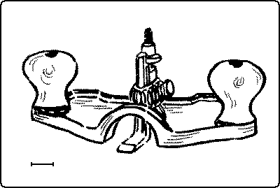
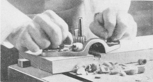
The dowel-pointer, Fig. 123, is a convenient tool for removing the sharp edges from the ends of dowel pins. It is held in a brace. The cutter is adjustable and is removable for sharpening.
The cornering tool, Fig. 124, is a simple device for rounding sharp corners. A cutter at each end cuts both ways so that it can be used with the grain without changing the position of the work. The depth of the cut is fixed.
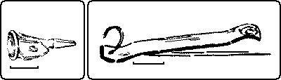
Some boring tools, like awls, force the material apart, and some, like augers, remove material.
The brad-awl, Fig. 125, is wedge-shaped, and hence care needs to be taken in using it to keep the edge across the grain so as to avoid splitting the wood, especially thin wood. The size is indicated by the length of the blade when new,—a stupid method. The awl is useful for making small holes in soft wood, and it can readily be sharpened by grinding.
[page 84]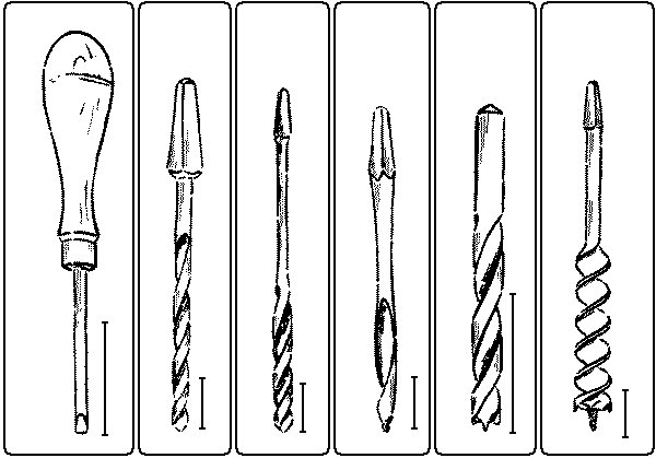
| 125 | 126 | 127 | 128 | 129 | 130 |
|
Fig. 125. Brad-Awl. Fig. 126. Twist-Drill. Fig. 127. Twist-Bit. Fig. 128. German Gimlet-Bit. Fig. 129. Bit-Point Drill. Fig. 130. Auger-Bit. |
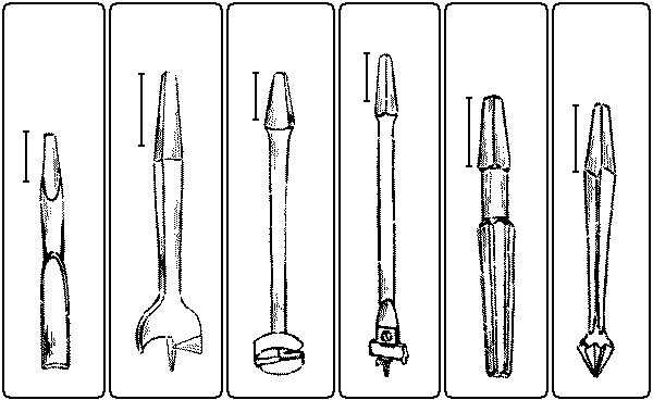
| 131 | 132 | 133 | 134 | 135 | 136 |
|
Fig. 131. Plug-Cutter. Fig. 132. Center-Bit. Fig. 133. Foerstner Auger-Bit. Fig. 134. Expansive-Bit. Fig. 135. Reamer. Fig. 136. Rose Countersink. |
Gimlets and drills are alike in that they cut away material, but unlike in that the cutting edge of the gimlet is on the side, while the cutting edge of the drill is on the end.
Twist-drills, Fig. 126, are very hard and may be used in drilling metal. They are therefore useful where there is danger of meeting nails, as in repair work. Their sizes are indicated by a special drill gage, Fig. 220, p. 116.
Twist-bits, Fig. 127, are like twist-drills except that they are not hard enough to use for metal. Their sizes are indicated on the tang in 32nds of an inch. Both twist-bits and drill-bits have the advantage over gimlet-bits in that they are less likely to split the wood.
Twist-bits and twist-drills are sharpened on a grindstone, care being taken to preserve the original angle of the cutting edge so that the edge will meet the wood and there will be clearance.
German gimlet-bits, Fig. 128, have the advantage of centering well. The size is indicated on the tang in 32nds of an inch. They are useful in boring holes for short blunt screws as well as deep holes. They cannot be sharpened readily but are cheap and easily replaced.
Bit-point drills, Fig. 129, are useful for accurate work, but are expensive.
Auger-bits, Fig. 130, have several important features. The spur centers the bit in its motion, and since it is in the form of a pointed screw draws the auger into the wood. Two sharp nibs on either side score the circle, out of which the lips cut the shavings, which are then carried out of the hole by the main screw of the tool. The size of auger-bits is indicated by a figure on the tang in 16ths of an inch. Thus 9 means a diameter of 9⁄16".
There are three chief precautions to be taken in using auger-bits. (1) One is to bore perpendicularly to the surface. A good way to do this is to lay the work flat, either on the bench or in the vise, and sight first from the front and then from the side of the work, to see that the bit is perpendicular both ways. The test may also be made with the try-square, Fig. 137, or with a plumb-line, either by the worker, or in difficult pieces, by a fellow worker. The sense of perpendicularity, however, should constantly be cultivated. (2) Another precaution is that, in thru boring, the holes should not be bored quite thru from one side, lest the wood be splintered off on the back. When the spur pricks thru, the bit should be removed, the piece turned over, and the boring finished, putting the spur in the hole which is pricked [page 86] thru in boring from the first side. It is seldom necessary to press against the knob of the brace in boring, as the thread on the spur will pull the bit thru, especially in soft wood. Indeed, as the bit reaches nearly thru the board, if the knob is gently pulled back, then when the spur pricks thru the bit will be pulled out of its hole. This avoids the necessity of constantly watching the back of the board to see if the spur is thru. (3) In stop boring, as in boring for dowels or in making a blind mortise, care should be taken not to bore thru the piece. For this purpose an auger-bit-gage, Fig. 219, p. 116, may be used, or a block of wood of the proper length thru which a hole has been bored, may be slipped over the bit, or the length of bit may be noted before boring, and then the length of the projecting portion deducted, or the number of turns needed to reach the required depth may be counted on a trial piece. Tying a string around a bit, or making a chalk mark on it is folly.
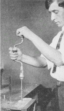
Auger-bits are sharpened with an auger-bit file, Fig. 142, p. 90, a small flat file with two narrow safe edges at one end and two wide safe edges at the other. The "nibs" should be filed on the inside so that the diameter of the cut may remain as large as that of the body of the bit. The cutting lip should be sharpened from the side toward the spur, care being taken to preserve the original angle so as to give clearance. If sharpened from the upper side, that is, the side toward the shank, the nibs will tend to become shorter.
The plug-cutter, Fig. 131, is useful for cutting plugs with which to cover the heads of screws that are deeply countersunk.
Center-bits, Fig. 132, work on the same principle as auger-bits, except that the spurs have no screw, and hence have to be pushed forcibly into the wood. Sizes are given in 16ths of an inch. They are useful for soft wood, and in boring large holes in thin material which is likely to split. They are sharpened in the same way as auger-bits.
[page 87]Foerstner bits, Fig. 133, are peculiar in having no spur, but are centered by a sharp edge around the circumference. The size is indicated on the tang, in 16ths of an inch. They are useful in boring into end grain, and in boring part way into wood so thin that a spur would pierce thru. They can be sharpened only with special appliances.
Expansive-bits, Fig. 134, are so made as to bore holes of different sizes by adjusting the movable nib and cutter. There are two sizes, the small one with two cutters, boring from ½" to 1½" and the large one with three cutters boring from ⅞" to 4". They are very useful on particular occasions, but have to be used with care.
Reamers, Fig. 135, are used for enlarging holes already made. They are made square, half-round and six cornered in shape.
Countersinks, Fig. 136, are reamers in the shape of a flat cone, and are used to make holes for the heads of screws. The rose countersink is the most satisfactory form.
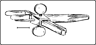
The washer-cutter, Fig. 138, is useful not only for cutting out washers but also for cutting holes in thin wood. The size is adjustable.
The primitive celt, which was hardly more than a wedge, has been differentiated into three modern hand tools, the chisel, see above, p. 53, the ax, Fig. 139, and the adze, Fig. 141.
The ax has also been differentiated into the hatchet, with a short handle, for use with one hand, while the ax-handle is long, for use with two hands. Its shape is an adaption to its manner of use. It is oval in order to be strongest in the direction of the blow and also in order that the axman may feel and guide the direction of the blade. The curve at the end is to avoid the awkward raising of the left hand at the moment of striking the blow, and the knob keeps it from slipping thru the hand. In both ax and hatchet there is a two-beveled edge. This is for the sake of facility in cutting into the wood at any angle.
[page 88]There are two principal forms, the common ax and the two bitted ax, the latter used chiefly in lumbering. There is also a wedge-shaped ax for splitting wood. As among all tools, there is among axes a great variety for special uses.
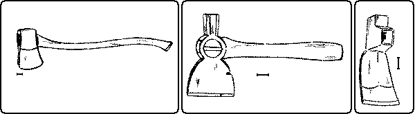
| Fig. 139. Ax. | Fig. 140. Shingling Hatchet. | Fig. 141. Carpenter's Adze. |
The hatchet has, beside the cutting edge, a head for driving nails, and a notch for drawing them, thus combining three tools in one. The shingling hatchet, Fig. 140, is a type of this.
The adze, the carpenter's house adze, Fig. 141, is flat on the lower side, since its use is for straightening surfaces.
[page 89]References:*
(1) Cutting.
Goss, p. 22.
Smith, R. H., pp. 1-8.
Chisel.
Barnard, pp. 59-73.
Selden, pp. 44-50, 145-147.
Barter, pp. 93-96.
Griffith, pp. 53-64.
Goss, pp. 20-26.
Sickels, pp. 64-67.
Wheeler, 357, 421, 442.
Knife.
Barnard, pp. 48-58.
Selden, pp. 26-28, 158.
Saw.
Griffith, pp. 20-27.
Barnard, pp. 114-124.
Selden, pp. 41-43, 179-182.
Wheeler, pp. 466-473.
Hammacher, pp. 309-366.
Goss, pp. 26-41.
Sickels, pp. 76-79, 84.
Smith, R. H., 43-55.
Diston, pp. 129-138.
Plane.
Barnard, pp. 74-80.
Selden, pp. 11-26, 165-175.
Sickels pp. 72-75, 116.
Wheeler, pp. 445-458.
Hammacher, pp. 377-400.
Smith, R. H., pp. 16-31.
Larsson, p. 19.
Goss, pp. 41-52.
Barter, pp. 96-109.
Griffith, pp. 28-45.
(2) Boring Tools.
Barnard, pp. 125-135.
Goss, pp. 53-59.
Griffith, pp. 47-52.
Seldon, pp. 38-40, 141-144.
Wheeler, pp. 353-356.
(3) Chopping Tools.
Barnard, pp. 80-88.
* For general bibliography see p. 4.
[page 90]Scraping tools are of such nature that they can only abrade or smooth surfaces.
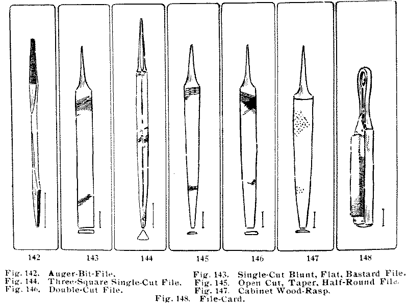
| 142 | 143 | 144 | 145 | 146 | 147 | 148 |
|
Fig. 142. Auger-Bit-File. Fig. 143. Single-Cut Blunt, Flat, Bastard File. Fig. 144. Three-Square Single-Cut File. Fig. 145. Open Cut, Taper, Half-Round File. Fig. 146. Double-Cut File. Fig. 147. Cabinet Wood-Rasp. Fig. 148. File-Card. |
Files. Figs. 142-146, are formed with a series of cutting edges or teeth. These teeth are cut when the metal is soft and cold and then the tool is hardened. There are in use at least three thousand varieties of files, each of which is adapted to its particular purpose. Lengths are measured from point to heel exclusive of the tang. They are classified: (1) according to their outlines into blunt, (i. e., having a uniform cross section thruout), and taper; (2) according to the shape of their [page 91] cross-section, into flat, square, three-square or triangular, knife, round or rat-tail, half-round, etc.; (3) according to the manner of their serrations, into single cut or "float" (having single, unbroken, parallel, chisel cuts across the surface), double-cut, (having two sets of chisel cuts crossing each other obliquely,) open cut, (having series of parallel cuts, slightly staggered,) and safe edge, (or side,) having one or more uncut surfaces; and (4) according to the fineness of the cut, as rough, bastard, second cut, smooth, and dead smooth. The "mill file," a very common form, is a flat, tapered, single-cut file.
Rasps, Fig. 147, differ from files in that instead of having cutting teeth made by lines, coarse projections are made by making indentations with a triangular point when the iron is soft. The difference between files and rasps is clearly shown in Fig. 149.
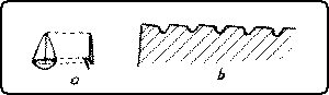
It is a good rule that files and rasps are to be used on wood only as a last resort, when no cutting tool will serve. Great care must be taken to file flat, not letting the tool rock. It is better to file only on the forward stroke, for that is the way the teeth are made to cut, and a flatter surface is more likely to be obtained.
Both files and rasps can be cleaned with a file-card, Fig. 148. They are sometimes sharpened with a sandblast, but ordinarily when dull are discarded.
Scrapers are thin, flat pieces of steel. They may be rectangular, or some of the edges may be curved. For scraping hollow surfaces curved scrapers of various shapes are necessary. Convenient shapes are shown in Fig. 150. The cutting power of scrapers depends upon the delicate burr or feather along their edges. When properly sharpened they take off not dust but fine shavings. Scrapers are particularly useful in smoothing cross-grained pieces of wood, and in cleaning off glue, old varnish, etc.
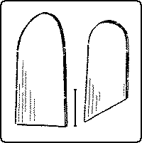
There are various devices for holding scrapers in frames or handles, such as the scraper-plane, Fig. 111, p. 79, the veneer-scraper, and box-scrapers. The veneer-scraper, Fig. 151, has the advantage that the blade may be sprung to a slight curve by a thumb-screw in [page 92] the middle of the back, just as an ordinary scraper is when held in the hands.
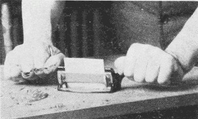
In use, Fig. 152, the scraper may be either pushed or pulled. When pushed, the scraper is held firmly in both hands, the fingers on the forward and the thumbs on the back side. It is tilted forward, away from the operator, far enough so that it will not chatter and is bowed back slightly, by pressure of the thumbs, so that there is no risk of the corners digging in. When pulled the position is reversed.
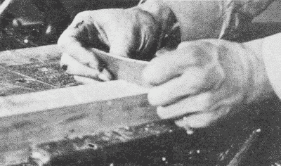
One method of sharpening the scraper is as follows: the scraper is first brought to the desired shape, straight or curved. This may be done either by grinding on the grindstone or by filing with a smooth, flat file, the scraper, while held in a vise. The edge is then carefully draw-filed, i. e., the file, a smooth one, is held (one hand at each end) directly at right angles to the edge of the scraper, Fig. 153, and moved sidewise from end to end of the scraper, until the edge is quite square with the sides. Then the scraper is laid flat on the oilstone and rubbed, first on one side and then on the other till the sides are bright and smooth along the edge, Fig. 154. Then it is set on edge on the stone and rubbed till there are two sharp square corners all along the edge, Fig. 155. Then it is put in the vise again and by means of a burnisher, or scraper steel, both of these corners are carefully turned or bent over so as to form a fine burr. This is done by tipping the scraper steel at a slight angle with the edge and rubbing it firmly along the sharp corner, Fig. 156.
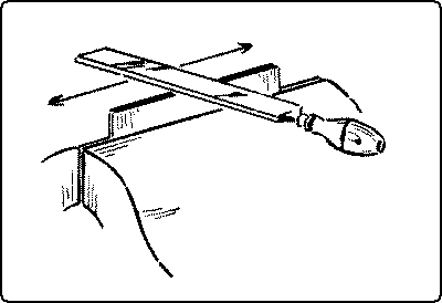
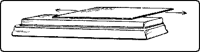
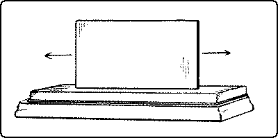
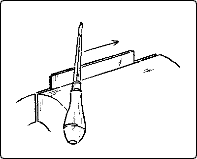
To resharpen the scraper it is not necessary to file it afresh every time, but only to flatten out the edges and turn them again with [page 93] slightly more bevel. Instead of using the oilstone an easier, tho less perfect, way to flatten out the burr on the edges is to lay the scraper flat on the bench near the edge. The scraper steel is then passed rapidly to and fro on the flat side of the scraper, Fig. 157. After that the edge should be turned as before.
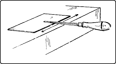
Sandpaper. The "sand" is crushed quartz and is very hard and sharp. Other materials on paper or cloth are also used, as carborundum, emery, and so on. Sandpaper comes in various grades of coarseness from No. 00 (the finest) to No. 3, indicated on the back of each sheet. For ordinary purposes No. 00 and No. 1 are sufficient. Sandpaper sheets may readily be torn by placing the sanded side down, one-half of the sheet projecting over the square edge of the bench. With a quick downward motion the projecting portion easily parts. Or it may be torn straight by laying the sandpaper on a bench, sand side down, holding the teeth of a back-saw along the line to be torn. In this case, the smooth surface of the sandpaper would be against the saw.
Sandpaper should never be used to scrape and scrub work into shape, but only to obtain an extra smoothness. Nor ordinarily should it be used on a piece of wood until all the work with cutting tools is done, for the fine particles of sand remaining in the wood dull the edge of the tool. Sometimes in a piece of cross-grained wood rough places will be discovered by sandpapering. The surface should then be wiped free of sand and scraped before using a cutting tool [page 94] again. In order to avoid cross scratches, work should be "sanded" with the grain, even if this takes much trouble. For flat surfaces, and to touch off edges, it is best to wrap the sandpaper over a rectangular block of wood, of which the corners are slightly rounded, or it may be fitted over special shapes of wood for specially shaped surfaces. The objection to using the thumb or fingers instead of a block, is that the soft portions of the wood are cut down faster than the hard portions, whereas the use of a block tends to keep the surface even.
Steel wool is made by turning off fine shavings from the edges of a number of thin discs of steel, held together in a lathe. There are various grades of coarseness, from No. 00 to No. 3. Its uses are manifold: as a substitute for sandpaper, especially on curved surfaces, to clean up paint, and to rub down shellac to an "egg-shell" finish. Like sandpaper it should not be used till all the work with cutting tools is done. It can be manipulated until utterly worn out.
The hammer consists of two distinct parts, the head and the handle. The head is made of steel, so hard that it will not be indented by hitting against nails or the butt of nailsets, punches, etc., which are comparatively soft. It can easily be injured tho, by being driven against steel harder than itself. The handle is of hickory and of an oval shape to prevent its twisting in the hand.
Hammers may be classified as follows: (1) hammers for striking blows only; as, the blacksmith's hammer and the stone-mason's hammer, and (2) [page 95] compound hammers, which consist of two tools combined, the face for striking, and the "peen" which may be a claw, pick, wedge, shovel, chisel, awl or round head for other uses. There are altogether about fifty styles of hammers varying in size from a jeweler's hammer to a blacksmith's great straight-handled sledge-hammer, weighing twenty pounds or more. They are named mostly according to their uses; as, the riveting-hammer, Fig. 159, the upholsterer's hammer, Fig. 160, the veneering-hammer, Fig. 162, etc. Magnetized hammers, Fig. 161, are used in many trades for driving brads and tacks, where it is hard to hold them in place with the fingers.
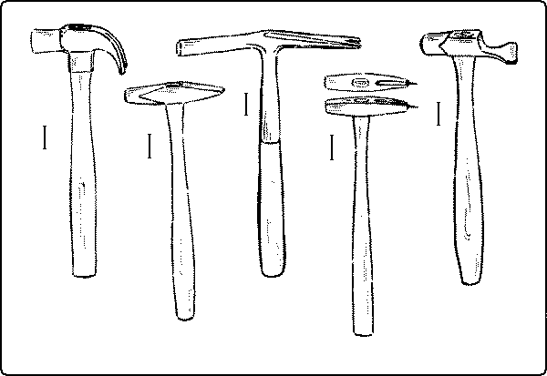
| 158 | 159 | 160 | 161 | 162 |
|
Fig. 158. Claw-Hammer. Fig. 159. Riveting-Hammer. Fig. 160. Upholster's Hammer. Fig. 161. Magnetized Hammer. Fig. 162. Veneering-Hammer. |
In the "bell-faced" hammer, the face is slightly convex, in order that the last blow in driving nails may set the nail-head below the surface. It is more difficult to strike a square blow with it than with a plain-faced hammer. For ordinary woodwork the plain-faced, that is, flat-faced claw-hammer, Fig. 158, is best. It is commonly used in carpenter work.
It is essential that the face of the hammer be kept free from glue in order to avoid its sticking on the nail-head and so bending the [page 96] nail. Hammers should be used to hit iron only; for hitting wood, mallets are used. In striking with the hammer, the wrist, the elbow and the shoulder are one or all brought into play, according to the hardness of the blow. The essential precautions are that the handle be grasped at the end, that the blow be square and quick, and that the wood be not injured. At the last blow the hammer should not follow the nail, but should be brought back with a quick rebound. To send the nail below the surface, a nailset is used. (See below.)
The claw is used for extracting nails. To protect the wood in withdrawing a nail a block may be put under the hammer-head. When a nail is partly drawn, the leverage can be greatly increased by continuing to block up in this way, Fig. 163.
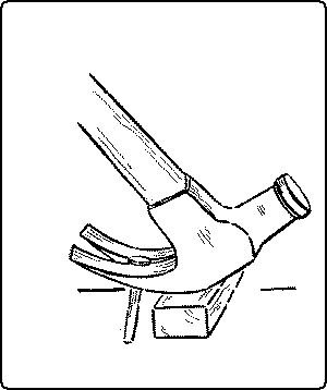
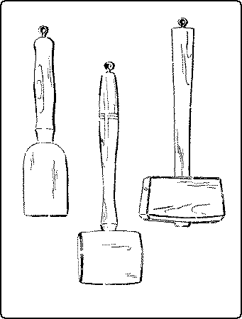
The mallet, Fig. 164, differs from the hammer in having a wooden instead of a steel head. A maul or beetle is a heavy wooden mallet. The effect of the blow of a mallet is quite different from that of a hammer, in that the force is exerted more gradually; whereas the effect of the hammer blow is direct, immediate, and local, and is taken up at once. But a mallet continues to act after the first impulse, pushing, as it were. This is because of the elasticity of the head. A chisel, therefore, should always be driven with a mallet, for the chisel handle would soon go to pieces under the blows of a hammer, because of their suddenness; whereas the mallet blow which is slower will not only drive the blade deeper with the same [page 97] force, but will not injure the handle so rapidly. Mallet-heads are made square, cylindrical, and barrel-shaped. Carver's mallets are often turned from one piece, hammer and head on one axis.
Nailsets, Fig. 165, are made with hardened points, but softer butts, so that the hammer will not be injured. They were formerly made square when nail heads were square, but now round ones are common. To obviate slipping, some have "cup points," that is, with a concave tip, and some spur points.
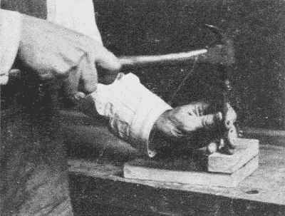
To keep the nailset in its place on the nail-head it may be held closely against the third finger of the left hand, which rests on the wood close to the nail. When a nailset is lacking, the head of a brad, held nearly flat, may be used. But care is necessary to avoid bruising the wood.
The advance in ease of handworking may largely be measured by the facilities for holding materials or other tools. The primitive man used no devices for holding except his hands and feet. The Japanese, who perhaps are the most skilful of joiners, still largely use their fingers and toes. On the other hand, Anglo-Saxons have developed an enormous variety of methods for holding work and tools.
[page 98]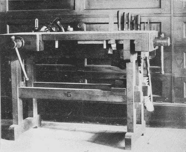
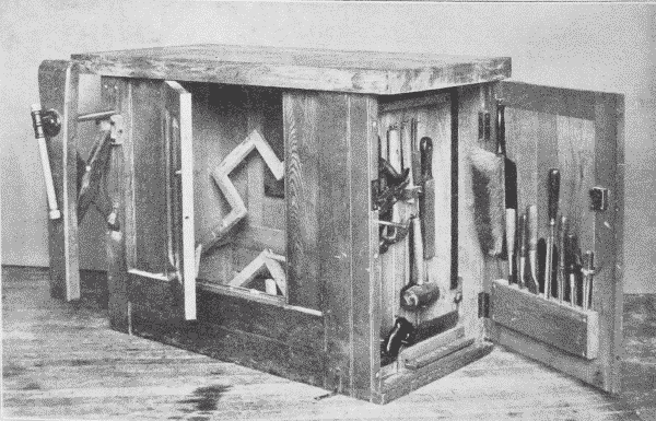
Benches. The essential features of a work-bench are a firm, steady table with a vise and places for tools. The joints are either pinned or wedged mortise-and-tenon, or draw-bolt joints. The best benches are made of maple, the tops being strips joined or tongued-and-grooved together. It is common also to have a trough at the back of the top of the bench, i. e., a space 6" or 8" wide, set lower than the upper surface, in which tools may be placed so as not to roll off. A low pillow, fastened at the left hand end of the trough, on which to set planes in order that the edge of the cutter may not be injured, is an advantage. The tool-rack is of capital importance. It has [page 99] been common in school benches to affix it to a board, which rises considerably above the top of the bench, Fig. 169, but a better plan is to have the top of it no higher than the bench-top, Fig. 166. Then the light on the bench is not obscured, and when a flat top is needed for large work it can readily be had by removing the tools. Elaborate benches with lock drawers are also much used in the shops of large city schools.
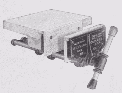
Vises for holding wood are of three general styles, (1) those with an upright wooden jaw, Fig. 167, which holds wide pieces of work well. They are now made with an automatic adjusting device by which the jaw and the face of the bench are kept parallel; (2) wooden vises with a horizontal jaw, guided by parallel runners, Fig. 166, and, (3) metal rapid-acting vises, Fig. 168. The latter are the most durable and in most respects more convenient. Special vises are also made for wood-carvers, for saw-filing, etc.
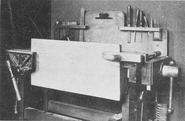
The best woodworking benches are equipped with both side- and tail-vises. The tail-vise is supplemented by movable bench-stops for [page 100] holding pieces of different lengths. In planing the side of a board it is held in place between the tail-vise and one of the bench-stops. A board should not be squeezed sidewise between the jaws of a vise when it is to be planed, lest it be bent out of shape. In planing the edge of a board it is ordinarily held in the side-vise. A long board, one end of which is in the vise, may also need to be supported at the other end. This may be done by clamping to it a handscrew, the jaw of which rests on the top of the bench, Fig. 169. When the vise is likely to be twisted out of square by the insertion of a piece of wood at one end of it, it is well to insert another piece of equal thickness at the other end of the vise to keep it square, as in Fig. 120, p. 82. In this case, (Fig. 120,) the extra piece also supports the piece being worked upon.
The vise is also of great use in carrying on many other processes, but a good workman does not use it to the exclusion of the saw-horse and bench-hook.
Horses are of great use both for the rough sawing of material and in supporting large pieces during the process of construction. The common form is shown in Fig. 170, but a more convenient form for sawing has an open top, as in Fig. 171.
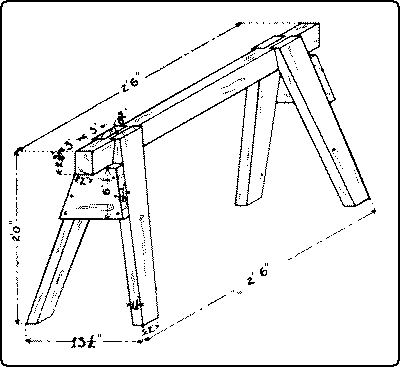
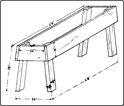
The picture-frame-vise, Fig. 172, is a very convenient tool for making mitered joints, as in picture-frames. The vise holds two sides firmly so that after gluing they may be either nailed together or a spline inserted in a saw cut previously made. See Fig. 268, [page 101] No. 55, p. 181. If the last joint in a picture-frame does not quite match, a kerf may be sawn at the junction of the two pieces, which can then be drawn close together.
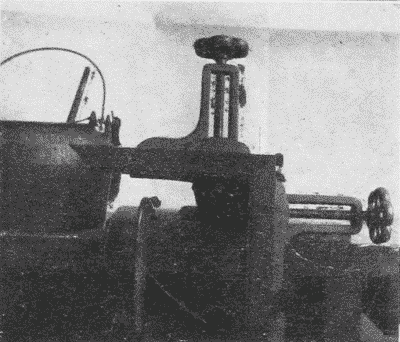
Handscrews, Fig. 173, consist of four parts, the shoulder jaw and the screw jaw, made of maple, and the end spindle and the middle spindle, made of hickory. The parts when broken can be bought separately. Handscrews vary in size from those with jaws four inches long to those with jaws twenty-two inches long. The best kind are oiled so that glue will not adhere to them. In adjusting the jaws, if the handle of the middle spindle is held in one hand, and the handle of the end spindle in the other hand, and both are revolved together, the jaws may be closed or opened evenly, Fig. 174. In use care must be taken to keep the jaws parallel, in order to obtain the greatest pressure and to prevent the spindles from being broken. It is always important to have the jaws press on the work evenly. To secure this, the middle spindle should be tightened first, and then the end spindle. Handscrews are convenient for a great variety of uses, as clamping up glued pieces, holding pieces together temporarily for boring, Fig. 247, p. 152, holding work at any desired angle in the vise, as for chamfering or beveling, Fig. 175, etc.
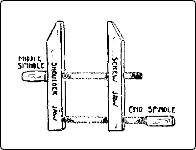
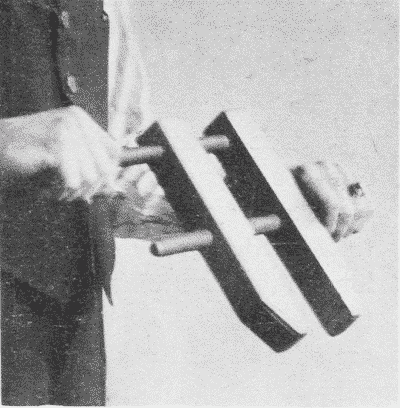
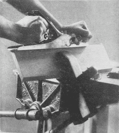
Clamps are made of both wood and iron, the most satisfactory for speed, strength, and durability are steel-bar carpenter clamps, Fig. 176. They vary in length from 1½ ft. to 8 ft. The separate parts are the steel bar A, the cast-iron frame B, the tip C [page 102] into which fits the screw D, on the other end of which is the crank E, and the slide F with its dog G, which engages in the notches on the bar. Any part, if broken, can be replaced separately.
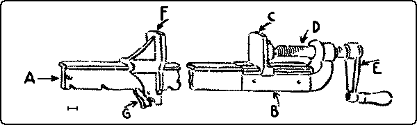
Iron Handscrews, also called C clamps and carriage-makers' clamps. Fig. 177, are useful in certain kinds of work, as in gluing in special places and in wood-carving. All iron clamps need blocks of soft wood to be placed between them and the finished work.
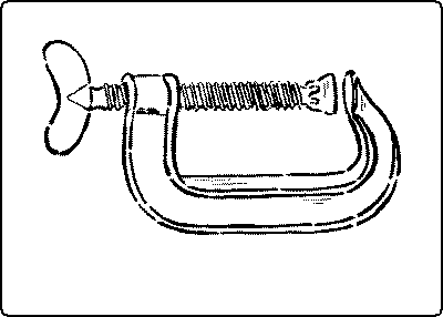
Pinch-dogs, Fig. 178, are a convenient device for drawing together two pieces of wood, when injury to the surfaces in which they are driven does not matter. They vary in size from ¾" to 2¾". For ordinary purposes the smallest size is sufficient. For especially fine work, double-pointed tacks, properly filed, are convenient.
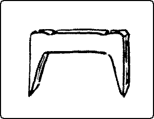
The bench-hook, Fig. 179, is a simple device for holding firmly small pieces of work when they are being sawn, chisled, etc. It also saves the bench from being marred. The angles should be kept exactly square.
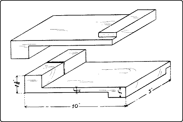
The miter-box, Fig. 180, is a similar device with the addition of a guide for the saw. The iron miter-box, Fig. 181, [page 103] with the saw adjustable to various angles, insures accurate work.
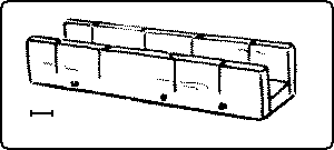
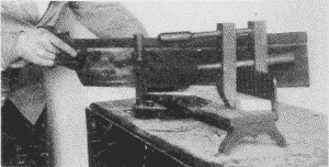
Such tools as pliers, Fig. 182, pincers, Fig. 183, and nippers, Fig. 184, made for gripping iron, are often useful in the woodworking shop. So are various sorts of wrenches; as fixed, socketed, adjustable, monkey- and pipe-wrenches.
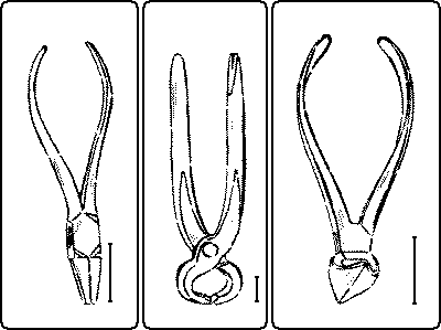
| Fig. 182. Pliers. | Fig. 183. Pincers. | Fig. 184. Nippers. |
The brace or bit-stock, Fig. 185, holds all sorts of boring tools as well as screwdrivers, dowel-pointers, etc. The simple brace or bit-stock consists of a chuck, a handle, and a knob, and is sufficient for ordinary use; but the ratchet-brace enables the user to bore near to surfaces or corners where a complete sweep cannot be made. It is also useful where sufficient power can be applied only at one part of the sweep. By means of pawls which engage in the ratchet-wheel, the bit can be turned in either direction at the will of the user. The size of the brace is indicated by the "sweep," that is, the diameter of the circle thru which the swinging handle turns. To insert a bit or other tool, Fig. 186, grasp firmly with one hand the sleeve of the chuck pointing it upward, and revolve the handle with the other hand, unscrewing the [page 104] sleeve until the jaws open enough to admit the whole tang of the bit. Then reverse the motion and the bit will be held tightly in place. Various hand-, breast-, bench-, bow-drills and automatic drills are of use in doing quick work and for boring small holes, Fig. 187.
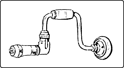
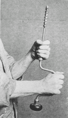
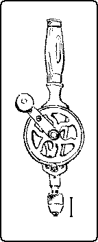
The screwdriver, Fig. 188, is a sort of holding tool for turning, and so driving screws. Various devices have been tried to prevent the twisting in the handle. This is now practically assured in various makes. The other important matter in a screwdriver is that the point be of the right temper, so as neither to bend nor to break. If the corners break they can be reground, but care should be taken not to make the angle too obtuse or the driver will slip out of the slot in the screw-head. The bevel should have a long taper. A shop should be equipped with different sizes of screwdrivers to fit the different sizes of screws. Screwdrivers vary in size, the shank ranging in length from 2½" to 18". A long screwdriver is more powerful than a short one, for the [page 105] screwdriver is rarely exactly in line with the axis of the screw, but the handle revolves in a circle. This means an increased leverage, so that the longer the screwdriver, the greater the leverage.
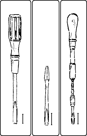
| 188 | 189 | 190 |
|
Fig. 188. Screwdriver. Fig. 189. Screwdriver-Bit. Fig. 190. Spiral Screwdriver. |
For heavy work, screwdriver-bits, Fig. 189, in a bit-stock are useful, and for quick work, the spiral screwdriver, Fig. 190, and for small work, the ratchet-screwdriver.
It is a long step from the time when one inch meant the width of the thumb, and one foot meant the length of the foot, to the measuring of distances and of angles which vary almost infinitesimally. No such accuracy is necessary in measuring wood as in measuring metal, but still there is a considerable variety of tools for this purpose.
For measuring distances, the rule, Fig. 191, is the one in most common use. It is usually made of boxwood. For convenience it is hinged so as to fold. A rule is called "two-fold" when it is made of two pieces, "four-fold" when made of four pieces, etc. When measuring or marking from it, it can be used more accurately by turning it on edge, so that the lines of the graduations may come directly against the [page 107] work. The one in most common use in school shops, is a two-foot, two-fold rule. Some instructors prefer to have pupils use a four-fold rule, because that is the form commonly used in the woodworking trades. Steel bench-rules, Fig. 192, are satisfactory in school work because unbreakable and because they do not disappear so rapidly as pocket rules. They need to be burnished occasionally.
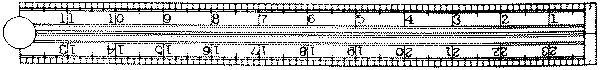
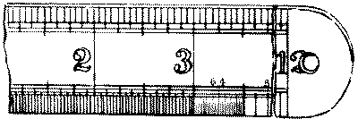
The steel square, Figs. 193, 194, 196, 197, is useful, not only as a straight-edge and try-square, but also for a number of graduations and tables which are stamped on it. There are various forms, but the one in most common use consists of a blade or "body" 24" × 2" and a "tongue," 16" × 1½", at right angles to each other. Sargent's trade number for this form is 100. It includes graduations in hundredths, thirty-seconds, sixteenths, twelfths, tenths, and eighths of an inch, also a brace-measure, an eight-square measure, and the Essex board-measure. Another style, instead of an Essex board-measure, and the hundredths graduation has a rafter-table. The side upon which the name of the maker is stamped, is called the "face," and the reverse side the "back."
The brace-measure is to be found along the center of the back of the tongue, Fig. 193. It is used thus: the two equal numbers set one above the other represent the sides of a square, and the single number to their right, represents in inches and decimals, the diagonal of that square.
| E. g., | 54 | 76.37 means that a square the sides of which are 54" would have a diagonal of 76.37". |
| 54 |
For determining the length of the long side (hypothenuse) of a right angle triangle, when the other two given sides are not equal, the foot rule, or another steel square may be laid diagonally across the [page 108] blade and arm, and applied directly to the proper graduations thereon, and the distance between them measured on the rule. If the distance to be measured is in feet, use the 1⁄12" graduations on the back of the square.
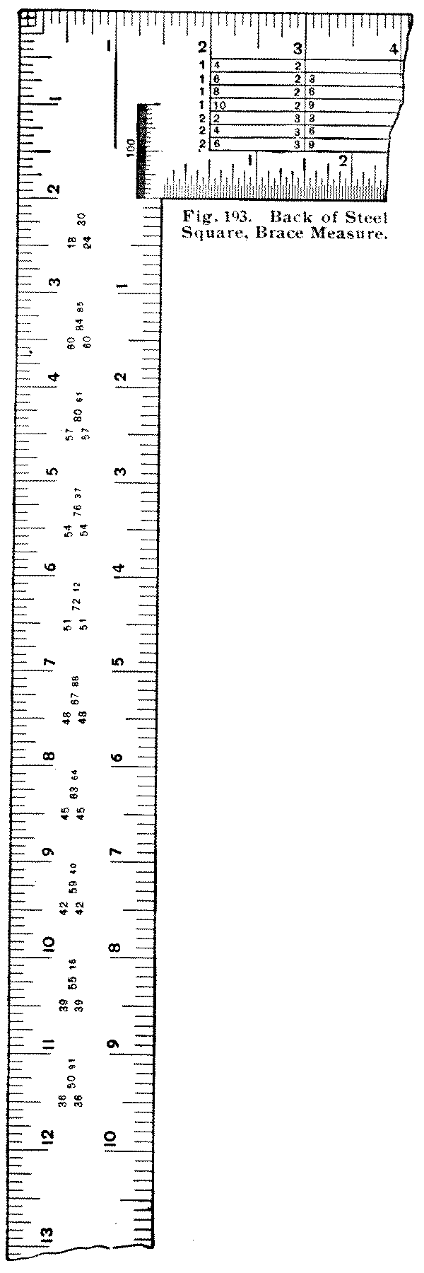
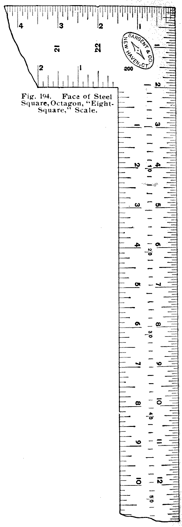
To use the octagonal (or 8-square) scale, Fig. 194, which is along the center of the face of the tongue, with the dividers, take the number of spaces in the scale to correspond with the number of inches the piece of wood is square, and lay this distance off from the center point, on each edge of the board. Connect the points thus obtained, diagonally across the corners, and a nearly exact octagon will be had. E.g., on a board 12" square, Fig. 195, find A.B.C.D., the centers of each edge. Now with the dividers take 12 spaces from the 8-square scale. Lay off this distance on each side as A' A" from A, B' B" from B, etc. Now connect A" with B', B" with C', C" with D', D" with A', and the octagon is obtained.
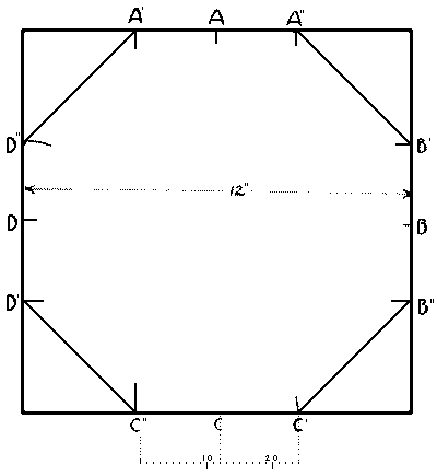
In making a square piece of timber octagonal, the same method is used on the butt, sawed true. When the distance from one center is laid off, the marking-gage may be set to the [page 109] distance from the point thus obtained to the corner of the timber, and the piece gaged from all four corners both ways. Cutting off the outside arrises to the gaged lines leaves an octagonal stick.
The board-measure is stamped on the back of the blade of the square, Fig. 196. The figure 12 on the outer edge of the blade is the starting point for all calculations. It represents a 1" board, 12" wide, and the smaller figures under it indicate the length of boards in feet. Thus a board 12" wide, and 8' long measures 8 square feet and so on down the column. To use it, for boards other than 12" wide:—find the length of the board in feet, under the 12" marked on the outer edge of the blade, then run right or left along that line to the width of the board in inches. The number under the width in inches on the line showing the length in feet, gives the board feet for lumber 1" thick.
For example, to measure a board 14' long, and 11" wide,—under the figure 12, find 14 (length of the board); to the left of this, under 11 is the number 12.10; 12' 10" is the board-measure of the board in question. Since a board 12' long would have as many board feet in it as it is inches wide, the B. M. is omitted for 12' boards. Likewise a board 6' long would have ½ the number of board feet that it is inches wide. If the board is shorter than the lowest figure given (8) it can be found by dividing its double by 2.; e. g., to measure a board 5' long and 9" wide, take 10 under the 12, run to the left of the number under 9, which is 7' 6"; ½ of this would be 3' 9", the number of board feet in the board.
[page 110]If the board to be measured is longer than any figure given, divide the length into two parts and add the result of the two parts obtained separately. For example, for a board 23' long and 13" wide,—take 12' × 13" =13'; add to it, 11' × 13"=11' 11"; total, 24'11".
A good general rule is to think first whether or not the problem can be done in one's head without the assistance of the square.
The table is made, as its name, Board-Measure (B. M.) implies, for measuring boards, which are commonly 1" thick. For materials more than 1" thick, multiply the B. M. of one surface by the number of inches thick the piece measures.
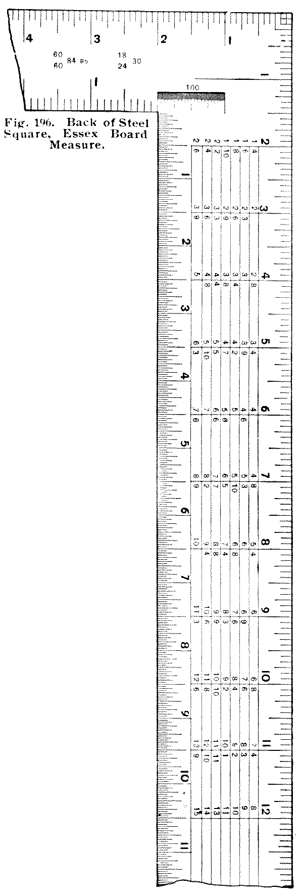
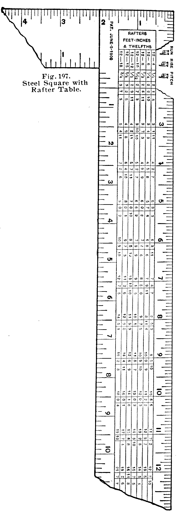
The rafter-table is found on the back of the body of the square, Fig. 197. Auxiliary to it are the twelfth inch graduations, on the outside edges, which may represent either feet or inches.
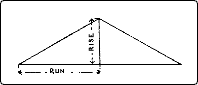
By the "run" of the rafter is meant the horizontal distance when it is set in place from the end of its foot to a plumb line from the ridge end, i. e., one half the length of the building, Fig. 198. By the "rise" of the rafter is meant the perpendicular distance from the ridge end [page 111] to the level of the foot of the rafter. By the pitch is meant the ratio of the rise to twice the run, i. e., to the total width of the building. In a ½ pitch, the rise equals the run, or ½ the width of the building; in a ⅓ pitch the rise is ⅓ the width of the building; in a ¾ pitch the rise is ¾ the width of the building.
To find the length of a rafter by the use of the table, first find the required pitch, at the left end of the table. Opposite this and under the graduation on the edge representing the run in feet, will be found the length of the rafter; e.g., a rafter having a run of 12' with a ¼ pitch, is 13' 5" long, one with a run of 11' and a ⅓ pitch, is 13' 28⁄12", one with a run of 7' and a ⅝ pitch, is 11' 26⁄12" long, etc.
When the run is in inches, the readings are for 1⁄12 of the run in feet: e.g., a rafter with a run of 12" and a ¼ pitch is 135⁄12", one with a run of 11" and a ⅓ pitch, is 133⁄12". Where the run is in both feet and inches, find the feet and the inches separately; and add together; e.g., a rafter with a run of 11' 6", and a ½ pitch, is 15' 68⁄12" + 86⁄12" = 16' 32⁄12".
The lumberman's board-rule, Fig. 199. To measure wood by it, note the length of the board in feet at the end of the measure. The [page 112] dot nearest the width (measured in inches) gives the B. M. for lumber 1" thick.
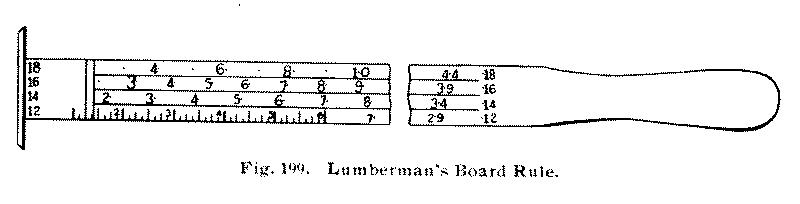
The try-square, Fig. 200, which is most commonly used for measuring the accuracy of right angles, is also convenient for testing the width of a board at various places along its length, for making short measurements, and as a guide in laying out lines with a pencil or knife at right angles to a surface or edge. The sizes are various and are indicated by the length of the blade. A convenient size for the individual bench and for ordinary use has a blade 6" long. It is also well to have in the shop one large one with a 12" blade.
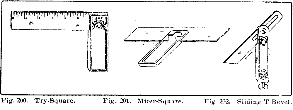
| Fig. 200. Try-Square. | Fig. 201. Miter-Square. | Fig. 202. Sliding-T Bevel. |
In testing the squareness of work with the try-square, care must be taken to see that the head rests firmly against the surface from which the test is made, and then slipped down till the blade touches the edge being tested, Fig. 203. The edge should be tested at a number of places in the same way: that is, it should not be slid along the piece. The try-square is also of great use in scribing lines across boards, Fig. 204. A good method is to put the point of the knife at the beginning of the desired line, slide the square, along until it touches the knife-edge; then, resting the head of the square firmly against the edge, draw the knife along, pressing it lightly against [page 113] the blade, holding it perpendicularly. To prevent the knife from running away from the blade of the try-square, turn its edge slightly towards the blade.
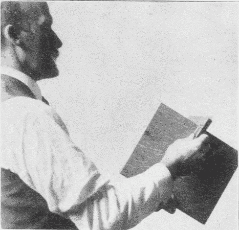
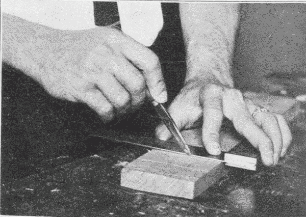
The miter-square, Fig. 201, is a try-square fixed at an angle of 45°.
The sliding T bevel, Fig. 202, has a blade adjustable to any angle. It may be set either from a sample line, drawn on the wood, from a given line on a protractor, from drawing triangles, from the graduations on a framing square, or in other ways. It is used similarly to the T-square.
| Fig. 200. Try-Square. | Fig. 201. Miter-Square. | Fig. 202. Sliding-T Bevel. |
Winding-sticks, Fig. 205, consist of a pair of straight strips of exactly the same width thruout. They are used to find out whether there is any twist or "wind" in a board. This is done by placing them parallel to each other, one at one end of the board, and the other at the other end. By sighting across them, one can readily see whether the board be twisted or not, Fig. 206. The blades of two framing-squares may be used in the same manner.
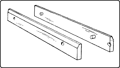
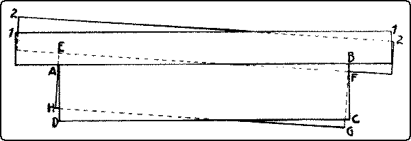
Compasses or dividers, Fig. 207, consist of two legs turning on a joint, and having sharpened points. A convenient form is the wing divider which can be accurately adjusted by set-screws. A pencil can be substituted for the removable point. They are used for describing circles and arcs, for spacing, for measuring, for subdividing distances, and for scribing. In scribing a line parallel with a given outline, one leg follows the given edge, or outline, and the point of the other, marks the desired line. Used in this way they are very convenient for marking out chamfers, especially on curved edges, a sharp pencil being substituted for the steel point.
[page 114]The beam-compass, Fig. 208, consists of two trammel-points running on a beam which may be made of any convenient length. It is used for describing large circles. A pencil may be attached to one point.
Calipers, outside and inside, Figs. 209, 210, are necessary for the accurate gaging of diameters, as in wood-turning.
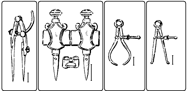
| 207 | 208 | 209 | 210 |
Fig. 207. Winged Dividers. Fig. 208. Beam-Compass or Trammel Points. Fig. 209. Outside Calipers. Fig. 210. Inside Calipers. |
The marking-gage, Fig. 211, consists of a head or block sliding on a beam or bar, to which it is fixed by means of a set-screw. On the face of the head is a brass shoe to keep the face from wearing. Projecting thru the beam is a steel spur or point, which should be filed to a flat, sharp edge, a little rounded and sharpened on the edge toward which the gage is to be moved, Fig. 212. It should project about ⅛" from the beam. If the spur be at all out of place, as it is likely to be, the graduations on a beam will be unreliable. Hence it is best to neglect them entirely when setting the gage and always to measure with the rule from the head to the spur, Fig. 213.
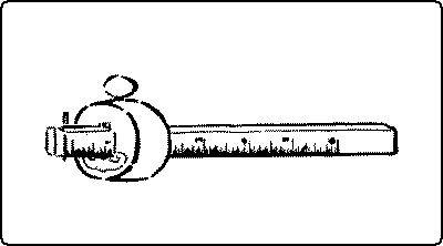
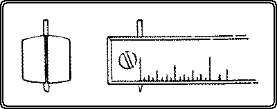
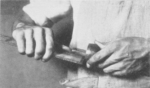
In use the beam should be tilted forward, so as to slide on its corner, Fig. 214. In this way [page 115] the depth of the gage line can be regulated. Ordinarily, the finer the line the better. The head must always be kept firmly pressed against the edge of the wood so that the spur will not run or jump away from its desired course. Care should also be taken, except in rough pieces, to run gage lines no farther than is necessary for the sake of the appearance of the finished work. To secure accuracy, all gaging on the surface of wood, should be done from the "working face" or "working edge."
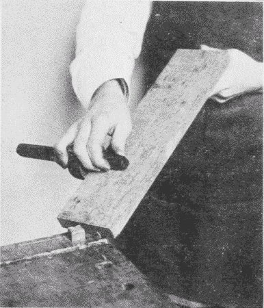
It is sometimes advisable, as in laying out chamfers, not to mark their edges with a marking-gage, because the marks will show after the chamfer is planed off. A pencil mark should be made instead. For this purpose a pencil-gage may be made by removing the spur of a marking-gage, and boring in its place a hole to receive a pencil stub with a blunt point, or a small notch may be cut in the back end of the beam, in which a pencil point is held while the gage is worked as usual except that its position is reversed. For work requiring less care, the pencil may [page 116] be held in the manner usual in writing, the middle finger serving as a guide, or a pair of pencil compasses may be used, one leg serving as a guide. A special gage is made for gaging curved lines, Fig. 215.
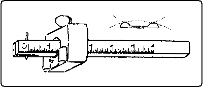
The cutting-gage, Fig. 216, is similar to a marking-gage, except that it has a knife-point inserted instead of a spur. It is very useful in cutting up soft, thin wood even as thick as ¼".
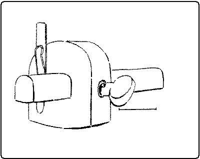
The slitting-gage is used in a similar way, but is larger and has a handle.
The mortise-gage, Fig. 217, is a marking-gage with two spurs, with which two parallel lines can be drawn at once, as in laying out mortises. One form is made entirely of steel having, instead of spurs, discs with sharpened edges.
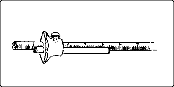
The scratch-awl, Fig. 218, has a long, slender point which is useful not only for marking lines, but for centering.
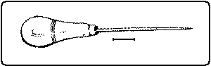
The auger-bit-gage, Fig. 219, is a convenient tool for measuring the depth of holes bored, but for ordinary purposes a block of wood sawn to the proper length thru which a hole is bored, is a satisfactory substitute.
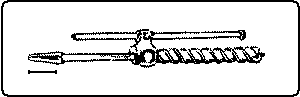
Screw- and wire-gages, Fig. 220, are useful in measuring the lengths and sizes of screws and wire when fitting or ordering.
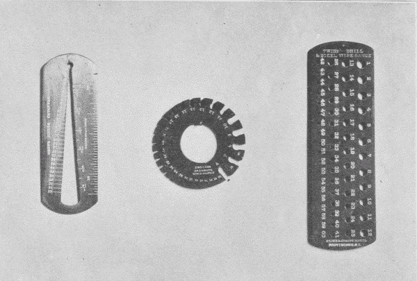
The spirit-level, and the plumb-line which it has largely replaced, are in constant use in carpentering, but are rarely needed in shopwork.
[page 117]Blackboard compasses, triangles, etc., are convenient accessories in a woodworking classroom.
The grindstone for woodworking tools is best when rather fine and soft. The grinding surface should be straight and never concave. The stone should run as true as possible. It can be made true by using a piece of 1" gas pipe as a truing tool held against the stone when run dry. Power grindstones usually have truing devices attached to them, Fig. 221. A common form is a hardened steel screw, the thread of which, in working across the face of the grindstone, as they both revolve, shears off the face of the stone. The surface should always be wet when in use both to carry off the particles of stone and steel, and thus preserve the cutting quality of the stone, and to keep the tool cool, as otherwise, its temper would be drawn, which would show by its turning blue. But a grindstone should never stand in water or it would rot.
[page 118]It is well to have the waste from the grindstone empty into a cisternlike box under it, Fig. 221. In this box the sediment will settle while the water overflows from it into the drain. Without such a box, the sediment will be carried into and may clog the drain. The box is to be emptied occasionally, before the sediment overflows.
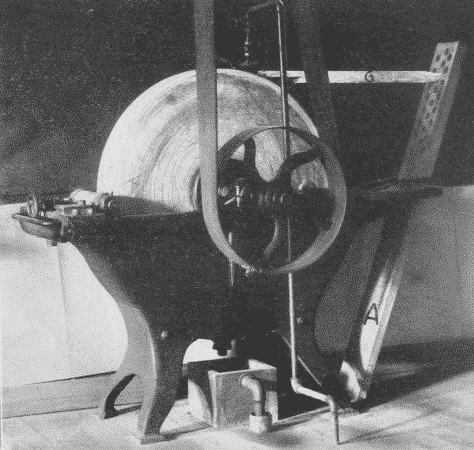
In order that the tool may be ground accurately, there are various devices for holding it firmly and steadily against the stone. A good one is shown in Figs. 221 and 222. This device is constructed as follows: A board A is made 2" thick, 6" wide, and long enough when in position to reach from the floor to a point above the level of the top of the stone. It is beveled at the lower end so as to rest snugly against a cleat nailed down at the proper place on the floor. The board is held in place by a loop of iron, B, which hooks into the holes in the trough of the grindstone. In the board a series of holes (say 1" in diameter) are bored. These run parallel to the floor when the board is in place, and receive the end of the tool-holder. [page 119] The tool-holder consists of four parts: (1) a strip C, 1½" thick, and as wide as the widest plane-bit to be ground. The forward end is beveled on one side; the back end is rounded to fit the holes in the main board A. Its length is determined by the distance from the edge of the tool being ground to the most convenient hole in A, into which the rear end is to be inserted. It is better to use as high a hole as convenient, so that as the grindstone wears down, the stick will still be serviceable; (2) a strip, D, of the same width as A and ⅞" thick, and 15" to 18" long; (3) a cleat, E, ⅝" × ¾", nailed across D; (4) a rectangular loop of wrought iron or brass, F, [page 120] which passes around the farther end of the two strips, C and D, and is fastened loosely to D by staples or screws.
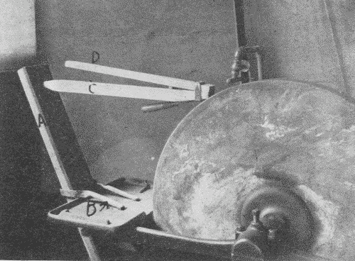
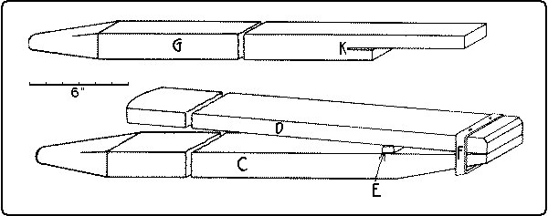
The tool to be ground slips between this loop and the strip C, and is held firmly in place by the pressure applied to the back end of D, which thus acts as a lever on the fulcrum E.
Any desired bevel may be obtained on the tool to be sharpened, by choosing the proper hole in A for the back end of C or by adjusting the tool forward or backward in the clamp. As much pressure may be put on the tool as the driving belt will stand without slipping off.
A still simpler holder for the plane-bit only, is a strip of wood 1½" thick and 2" wide, cut in the shape G shown in Fig. 223. The plane-bit fits into the saw-kerf K, and in grinding is easily held firmly in place by the hand. By inserting the rear end of the stick G into a higher or lower hole in the board A, any desired angle may be obtained. G is shown in position in Fig. 221.
All such devices necessitate a perfectly true stone. The essential features are, to have a rigid support against which the tool may be pushed by the revolving stone, to hold the tool at a fixed angle which may be adjusted, and to press the tool against the stone with considerable pressure. The wheel should revolve toward the edge which is being ground, for two reasons. It is easier to hold the tool steadily thus, and the danger of producing a wire edge is lessened. The edge as it becomes thin, tends to spring away from the stone and this tendency is aggravated if the stone revolves away from the edge. If the stone does not run true and there is a consequent danger of digging into the stone with the tool which is being sharpened, the stone would better revolve away from the edge. The grinding should continue until the ground surface reaches the cutting edge and there is no bright line left along the edge. If the grinding is continued beyond this point, nothing is gained, and a heavy wire edge will be formed.
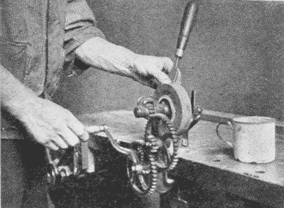
A very convenient and inexpensive grinding tool, Fig. 224, sold as the "Agacite grinder,"7 has a number of different shaped grinding stones made chiefly of carborundum.
Footnote 7: Made by the Empire Implement Co., Albany, N. Y.
The oilstone. After grinding, edge tools need whetting. This is done on the whetstone, or oilstone. The best natural stones are found near Hot Springs, Arkansas. The fine white ones are called Arkansas stones, and the coarser ones Washita stones. The latter are better for ordinary woodworking tools. The India oilstone, an artificial stone, Fig. 77, p. 58, cuts even more quickly than the natural stones. It is made in several grades of coarseness. The medium grade is recommended for ordinary shop use. Oil is used on oilstones for the same purpose as water on a grindstone. When an oilstone becomes hollow or uneven by use, it may be trued by rubbing it on a flat board covered with sharp sand, or on sandpaper tacked over a block of wood.
Slipstones, Fig. 225, are small oilstones, made into various shapes in order to fit different tools, as gouges, the bits of molding-planes, etc.
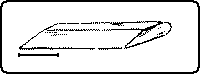
Files are used for sharpening saws, augers, scrapers, etc. See above, p. 90.
The bench duster. One may be noted hanging on the bench shown in Fig. 166, p. 98. Bristle brushes for cleaning the benches are essential if the shop is to be kept tidy.
Buffer. Wherever a lathe or other convenient revolving shaft is available, a buffer made of many thicknesses of cotton cloth is very valuable for polishing tools. The addition of a little tripoli greatly facilitates the cleaning.
[page 122]References:*
(4) Scraping Tools.
Barnard, pp. 136-142.
Wheeler, pp. 465, 473.
Griffith, pp. 71-75.
Selden, pp. 149, 177, 182.
Hodgson, I, pp. 61-74.
(5) Pounding Tools.
Barnard, pp. 24-47.
Sickels, p. 70.
Wheeler, pp. 414, 428-432.
Selden, pp. 31, 111, 156.
Goss, p. 60.
Barter, p. 128.
(6) Punching Tools.
Barnard, p. 29.
Wheeler, p. 433.
Selden, p. 161.
(7) Gripping Tools.
For holding work:
Goss, p. 63.
Wheeler, pp. 65-75, 475.
Selden, pp. 140, 147, 186, 194.
Hammacher, pp. 286-291.
For holding other tools:
Goss, pp. 56-59.
Selden, p. 143.
(8) Measuring and Marking Tools.
Goss, pp. 9-20.
Griffith, pp. 9-19.
Hodgson, The Steel Square.
Wheeler, p. 465.
Tate, pp. 21-25.
Building Trades Pocketbook, pp. 234-237.
Selden, pp. 149, 150-152, 175.
Sargent's Steel Squares.
(9) Sharpening Tools.
Barnard, pp. 136-142.
Sickels, pp. 80-85.
Wheeler, pp. 480-488.
Selden, pp. 153, 162, 172, 180.
Goss, pp. 39, 64-69.
* For general bibliography see p. 4.
[page 123]The following are the chief means by which pieces of wood are fastened together: nails, screws, bolts, plates, dowels, glue, hinges, and locks.
Nails, Fig. 226, may be classified according to the material of which they are made; as, steel, iron, copper, and brass. Iron nails may be galvanized to protect them from rust. Copper and brass nails are used where they are subject to much danger of corrosion, as in boats.
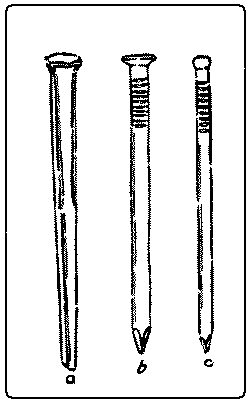
| Fig. 226. |
| a. Cut nail, common. |
| b. Flat-head wire nail, No. 1, common. |
| c. Finishing nail, or brad. |
Nails may also be classified according to the process of manufacture; as, cut nails, wrought nails, and wire nails. Cut nails are cut from a plate of metal in such a way that the width of the nail is equal to the thickness of the plate, and the length of the nail to the width of the plate. In the third dimension, the nail is wedge-shaped, thin at the point and thick at the head. Unless properly driven, such nails are likely to split the wood, but if properly driven they are very firm. In driving, the wedge should spread with and not across the grain.
Wrought nails are worked into shape from hot steel, and have little or no temper, so that they can be bent over without breaking, as when clinched. Horseshoe- and trunk-nails are of this sort. They are of the same shape as cut nails.
Wire nails are made from drawn steel wire, and are pointed, headed, and roughened by machinery. They are comparatively cheap, hold nearly if not quite as well as cut nails, which they have largely displaced, can be bent without breaking, and can be clinched.
[page 124]Nails are also classified according to the shape of their heads; as, common or flat-heads, and brads or finishing nails. Flat-heads are used in ordinary work, where the heads are not to be sunk in the wood or "set."
Some nails get their names from their special uses; as, shingle-nails, trunk-nails, boat-nails, lath-nails, picture-nails, barrel-nails, etc.
The size of nails is indicated by the length in inches, and by the size of the wire for wire nails. The old nomenclature for cut nails also survives, in which certain numbers are prefixed to "penny." For example, a threepenny nail is 1¼" long, a fourpenny nail is 1½" long, a fivepenny nail is 1¾" long, a sixpenny nail is 2" long. In other words, from threepenny to tenpenny ¼" is added for each penny, but a twelvepenny nail is 3¼" long, a sixteenpenny nail is 3½" long, a twentypenny nail is 4" long. This is explained as meaning that "tenpenny" nails, for example, cost tenpence a hundred. Another explanation is that originally 1000 of such nails weighed a pound. The size of cut nails is usually still so indicated. Nails are sold by the pound.
The advantages of nails are that they are quickly and easily applied, they are strong and cheap, and the work can be separated, tho with difficulty. The disadvantages are the appearance and, in some cases, the insecurity.
The holding power of nails may be increased by driving them into the wood at other than a right angle, especially where several nails unite two pieces of wood. By driving some at one inclination and some at another, they bind the pieces of wood together with much greater force than when driven in straight.
The term brads was once confined to small finishing nails, but is now used for all finishing nails, in distinction from common or flat-headed nails. The heads are made round instead of flat so that they may be set easily with a nailset and the hole filled with a plug, or, where the wood is to be painted, with putty. They are used for interior finishing and other nice work.
Tacks, Fig. 227, vary in size and shape according to their use; as, flat-headed, gimp, round-headed, and double-pointed or matting tacks, a sort of small staple. Their size is indicated by the word "ounce." For example, a two-ounce tack is ¼" long, a three-ounce [page 125] tack is ⅜" long, a four-ounce tack is 7⁄16" long, a six-ounce tack is ½" long, etc. This term once meant the number of ounces of iron required to make 1000 tacks.
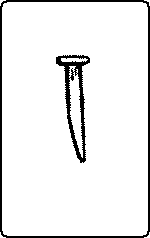
Tacks are useful only in fastening to wood thin material, such as veneers, textiles, leather, matting, tin, etc. Tinner's tacks, which are used for clinching, are commonly called clinch-nails. Wire tacks, altho made, are not so successful as cut tacks because they lack a sharp point, which is essential.
Corrugated fasteners, Fig. 228, or fluted nails, are used to fasten together two pieces of wood by driving the fastener so that one-half of it will be on each side of the joint. Their size is indicated by the length and the number of corrugations, as ½", four. They are often useful where nails are impracticable.
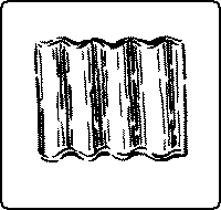
Glaziers' points are small, triangular pieces of zinc, used to fasten glass into sashes.
(a) Wood-screws, Fig. 229, may be classified by the material of which they are made; as, steel or brass. Steel screws may be either bright,—the common finish,—blued by heat or acid to hinder rusting, tinned, or bronzed. Brass screws are essential wherever rust would be detrimental, as in boats.
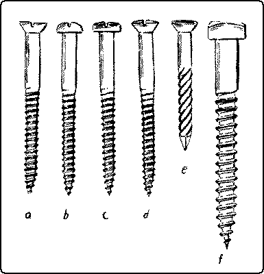
| Fig. 229. |
| a. Flat-head Wood-screw. |
| b. Round-head Wood-screw. |
| c. Fillister-head Wood-screw. |
| d. Oval-countersunk-head Wood-screw. |
| e. Drive-screw. |
| f. Square-head (lag- or coach-) Screw. |
(b) Screws are also classified by shape; as, flat-headed, round-headed, fillister-headed, oval-countersunk-headed, and square-headed screws. Flat-heads are most commonly used. There are also special shapes for particular purposes. Round-heads may be used either for decoration or where great drawing power is desirable. In the latter case, washers are commonly inserted under the heads to prevent them from sinking into the wood. Oval-heads are used decoratively, the head filling the countersunk hole, as with flat-heads, and projecting a trifle besides. They are much used in the interior finish of railway cars. They are suitable for the strap hinges of a chest.
The thread of the screw begins in a fine point so that it may penetrate the wood easily where no hole has been bored as is often the case in soft wood. The thread extends about two-thirds the length of the screw. Any longer thread would only weaken the [page 126] screw where it most needs strength, near the head, and it does not need friction with the piece thru which it passes.
The size of screws is indicated by their length in inches, and by the diameter of the wire from which they are made, using the standard screw-gage, Fig. 220, p. 116. They vary in size from No. 0 (less than 1⁄16") to No. 30 (more than 7⁄16") in diameter, and in length from ¼" to 6".
The following is a good general rule for the use of screws: make the hole in the piece thru which the screw passes, large enough for the screw to slip thru easily. Countersink this hole enough to allow the head to sink flush with the surface. Make the hole in the piece into which the screw goes small enough for the thread of the screw to catch tight. Then all the strength exerted in driving, goes toward drawing the pieces together, not in overcoming friction. The hole must be deep enough, especially in hard wood and for brass screws, to prevent the possibility of twisting off and breaking the screw. Soap is often useful as a lubricant to facilitate the driving of screws. Where it is desirable that the heads do not show, a hole may first be bored with an auger-bit large enough to receive the head and deep enough to insert a plug of wood, which is cut out with a plug-cutter, Fig. 131, p. 84, and glued in place. If pains are taken to match the grain, the scar thus formed is inconspicuous.
In rough work, the screw may be driven into place with a hammer thru most of its length, and then a few final turns be given with a screwdriver, but this breaks the fibers of the wood and weakens their hold. In "drive-screws," Fig. 229, e, the slot is not cut all the way across the head, in order that the blows of the hammer may not close the slot.
The advantages of screws are, that they are very strong and that the work can easily be taken apart. If they loosen they can be [page 127] retightened. The disadvantages are, that they are expensive, that they take time to insert, that they show very plainly, and that they do not hold well in end grain.
Bolts with nuts are useful where great strength is desired. There are three chief varieties, Fig. 230.
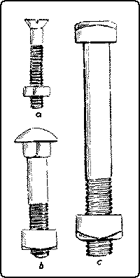
| Fig. 230. |
| a. Stove-bolt. |
| b. Carriage-bolt. |
| c. Machine-bolt. |
Stove-bolts are cheaply made (cast) bolts having either flat or round heads with a slot for the screwdriver, like ordinary screws.
Carriage-bolts are distinguished by having the part of the shank which is near the head, square.
Machine-bolts have square, hexagonal, or button heads.
Machine-screws, Fig. 231, are similar to stove-bolts, but are accurately cut and are measured with a screw-gage. The varieties are, a, flat-head, b, round-head, c, fillister-head, d, oval-countersunk-head, all with slots for screwdriver.
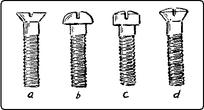
| Fig. 231. Machine-screws. |
| a. Flat-head. |
| b. Round-head. |
| c. Fillister-head. |
| d. Oval-countersunk-head. |
Plates, Fig. 232, include corner-irons, straight plates and panel-irons. These are made of either iron or brass and are used in fastening legs to the floor, in stiffening joints, affixing tops, etc.
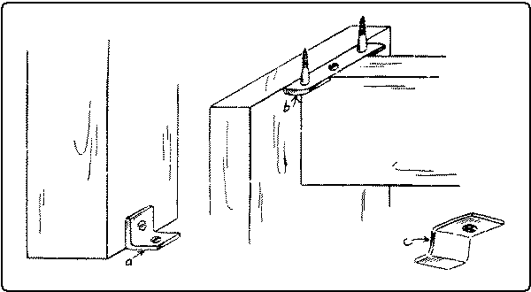
| Fig. 232. |
| a. Corner-iron. |
| b. Straight plate. |
| c. Panel-iron. |
Dowel-rods. Dowel-rods are cylindrical rods, from 3⁄16" to 1" in diameter, and 36", 42", and 48" long. They are commonly made of birch or maple, but maple is more satisfactory as it shrinks less and is stronger than birch.
Dowels are used as pins for joining boards edge to edge, and as a substitute for mortise-and-tenon joints.
There is, to be sure, a prejudice against dowels on the part of cabinet-makers due, possibly, to the willingness to have it appear that doweling is a device of inferior mechanics. But doweling is cheaper and quicker than tenoning, [page 128] and there are many places in wood construction where it is just as satisfactory and, if properly done, just as strong. Certain parts of even the best furniture are so put together.
Shoe pegs serve well as small dowels. They are dipped in glue and driven into brad-awl holes.
Wedges are commonly used in door construction between the edges of tenons and the insides of mortises which are slightly beveled, No. 34, Fig. 266, p. 179. Or the end of a tenon may be split to receive the wedges, No. 35, Fig. 266. The blind wedge is used in the fox-tail joint, No. 36, Fig. 266.
Glue is an inferior kind of gelatin, and is of two kinds,—animal glue and fish glue. Animal glue is made of bones and trimmings, cuttings and fleshings from hides and skins of animals. Sinews, feet, tails, snouts, ears, and horn pith are also largely used. Cattle, calves, goats, pigs, horses, and rabbits, all yield characteristic glues.
The best glue is made from hides of oxen, which are soaked in lime water until fatty or partly decayed matter is eaten out and only the glue is left. The product is cleaned, boiled down and dried.
The best and clearest bone glues are obtained by leaching the bones with dilute acid which dissolves out the lime salts and leaves the gelatinous matters. Such leached bone is sold as a glue stock, under the name of "osseine." This material together with hides, sinews, etc., has the gelatin or glue extracted by boiling again and again, just as soup stock might be boiled several times. Each extraction is called a "run." Sometimes as many as ten or fifteen runs are taken from the same kettle of stock, and each may be finished alone or mixed with other runs from other stock, resulting in a great variety of commercial glues.
[page 129]Manufacturers use many tests for glue, such as the viscosity or running test, the odor, the presence of grease or of foam, rate of set, the melting-point, keeping properties, jelly strength (tested between the finger tips), water absorption (some glues absorb only once their weight, others ten or twelve times), and binding or adhesive tests. This latter varies so much with different materials that what may be good glue for one material is poor for another.
Putting all these things together, glues are classified from grade 10 to 160, 10 being the poorest. The higher standards from 60 and upwards are neutral hide glues, clear, clean, free from odor, foam, and grease. The lower standards are chiefly bone glues, used for sizing straw hats, etc. They are rigid as compared with the flexibility of hide glues. For wood joints the grade should be 70 or over. For leather, nothing less than 100 should be used, and special cements are better still.
The best glue is transparent, hard in the cake, free from spots, of an amber color, and has little or no smell. A good practical test for glue is to soak it in water till it swells and becomes jelly-like. The more it swells without dissolving the better the quality. Poor glue dissolves. Glue is sometimes bleached, becoming brownish white in color, but it is somewhat weakened thereby.
Fish glue is made from the scales and muscular tissue of fish. Isinglass is a sort of glue made from the viscera and air bladder of certain fish, as cod and sturgeon.
Liquid glue may be made either from animal or fish glue. The LePage liquid glue is made in Gloucester, Mass., one of the greatest fish markets in the country. Liquid glue is very convenient because always ready, but is not so strong as hot glue, and has an offensive odor. Liquid glues are also made by rendering ordinary glue non-gelatinizing, which can be done by several means; as, for instance, by the addition of oxalic, nitric, or hydrochloric acid to the glue solution.
To prepare hot glue, break it into small pieces, soak it in enough cold water to cover it well, until it is soft, say twelve hours, and heat in a glue-pot or double boiler, Fig. 243, p. 149. The fresher the glue is, the better, as too many heatings weaken it. When used it should be thin enough to drip from the brush in a thin stream, so that it will fill the pores of the wood and so get a grip. Two surfaces to be glued together should be as close as possible, not separated [page 130] by a mass of glue. It is essential that the glue be hot and the wood warm, so that the glue may remain as liquid as possible until the surfaces are forced together. Glue holds best on side grain. End grain can be made to stick only by sizing with thin glue to stop the pores. Pieces thus sized and dried can be glued in the ordinary way, but such joints are seldom good. Surfaces of hard wood that are to be glued should first be scratched with a scratch-plane, Fig. 111, p. 79.
To make waterproof glue, add one part of potassium bichromate to fifty parts of glue. It will harden when exposed to the air and light and be an insoluble liquid.8
Footnote 8: For recipes for this and other glues, see Woodcraft, May '07, p. 49.
General directions for gluing.9 Before applying glue to the parts to be fastened together, it is a good plan to assemble them temporarily without glue, to see that all the parts fit. When it is desirable that a certain part, as the panel, in panel construction, should not be glued in place, it is a wise precaution to apply wax, soap, or oil to its edges before insertion. Since hot glue sets quickly, it is necessary after the glue is applied to get the parts together as soon as possible. One must learn to work fast but to keep cool. To expedite matters, everything should be quite ready before the process is begun, clamps, protecting blocks of wood, paper to protect the blocks from sticking to the wood, braces to straighten angles, mallet, try-square, and all other appliances likely to be required.
Footnote 9: For special directions, for particular joints, see under the various joints, (Chap. VII.)
Whenever it is possible to break up the process into steps, each step can be taken with more deliberation. For example, in assembling framed pieces that are doweled, it is well to glue the dowels into one set of holes beforehand, making tenons of them, as it were. Time is thus saved for the final assembling when haste is imperative. The superfluous glue around the dowels should be carefully wiped off.
Likewise in gluing up framed pieces, sections may be put together separately: as, the ends of a table, and when they are dry then the whole may be assembled. When the pieces are together the joints should be tested to see that they are true, and that there are no twists.
A good way to insure squareness, is to insert a diagonal brace on the inside, corner to corner, as in Fig. 294, p. 196. Such a brace [page 131] should be provided when the trial assembly is made. Another good way to insure squareness is to pass a rope around two diagonally opposite posts, and then by twisting the rope, to draw these corners toward each other until the frame is square.
The superfluous glue may be wiped off at once with a warm damp cloth, but not with enough water to wet the wood. Or by waiting a few minutes until the glue thickens, much of it can readily be peeled off with an edge tool. Either of these ways makes the cleaning easier than to let the superfluous glue harden.
The work when glued should remain at least six hours in the clamps to harden.
Hinges, Fig. 233, are made in several forms. The most common are the butt-hinge or butt, the two leaves of which are rectangular, as in a door-hinge; the strap-hinge, the leaves of which are long and strap-shaped; the Tee-hinge, one leaf of which is a butt, and the other strap-shaped; the chest-hinge, one leaf of which is bent at a right angle, used for chest covers; the table-hinge used for folding table tops with a rule joint; the piano-hinge, as long as the joint; the blank hinge or screen-hinge which opens both ways; the stop-hinge, which opens only 90°; and the "hook-and-eye" or "gate" hinge.
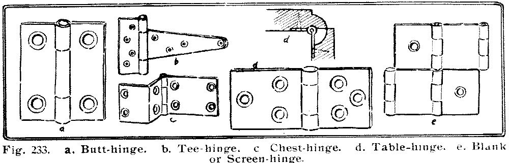
| Fig. 233. |
| a. Butt-hinge. |
| b. Tee-hinge. |
| c. Chest-hinge. |
| d. Table-hinge. |
| e. Blank or Screen-hinge. |
The knuckle of the hinge is the cylindrical part that connects the two leaves, Fig. 234. The "acorn" is the head of the "pintle" or pin that passes thru the knuckle. Sizes of butts are indicated in inches for length, and as "narrow," "middle," "broad" and "desk" for width. The pin may be either riveted into the knuckle as in box-hinges or removable as in door-butts. Sometimes, as in blind-hinges, [page 132] the pintle is fastened into one knuckle, but turns freely in the other.
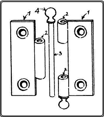
| Fig. 234. Parts of a butt-hinge. |
| 1.1. Leaves. |
| 2.2.2. Knuckle. |
| 3. Pintle. |
| 4. Acorn. |
A butt-hinge may be set in one of three positions, Fig. 235: (1) Where it is desired to have the hinge open as wide as possible, as in a door. Here the knuckle is set well out from the wood. (2) Where it is desired to have the hinged portion open flat and no more. Here the center of the pin is in line with the outside surface of the wood. This is less likely to rack the hinge than the other two positions. (3) Where it is desired to have the knuckle project as little as possible.
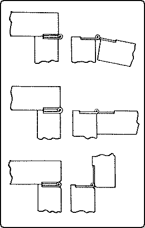
In setting the hinges of a box cover, first see that the cover fits the box exactly all the way around.
In the case of a door, see that it fits its frame, evenly all the way around, but with a little play. To insure a tighter fit at the swinging edge this edge should be slightly beveled inwards.
In attaching a butt-hinge, the essential thing is to sink the hinge into the wood, exactly the thickness of the knuckle. The gains may be cut in one or both of the pieces to be hinged together.
With these matters determined proceed as follows: In the case of a box cover, the hinges should be set about as far from the ends of the box as the hinge is long.
In the case of an upright door, locate the hinges respectively above and below the lower and upper rails of the door. Mark with the knife on the edge of the door the length of the hinge, and square across approximately the width of the gain to receive it. Do this for both hinges. Between these lines gage the proper width of the gains. Set another gage to one half the thickness of the knuckle and gage on the door face the depth of the gains. Chisel out the gains, set the hinges in place, bore the holes, and drive the screws. Place the door in position again to test the fit. If all is well, mark the position of the hinges on the frame, gage and cut the gains, and fasten in the hinges. Where the hinge is gained its full thickness into the door, [page 133] no gain, of course, is cut in the frame. If the hinges are set too shallow, it is an easy matter to unscrew one leaf of each and cut a little deeper. If they are set too deep the screws may be loosened and a piece of paper or a shaving inserted underneath along the outer arris of the gain.
The chief parts of a lock are: the bolt, its essential feature, the selvage, the plate which appears at the edge of the door or drawer, the box, which contains the mechanism including the tumbler, ward, spring, etc., the key-pin, into or around which the key is inserted, the strike, the plate attached opposite the selvage, (often left out as in drawer-locks, but essential in hook-bolt locks, and self-locking locks,) and the escutcheon, the plate around the keyhole.
Locks may be classified: (1) According to their uses, of which there are two types. (a), Fig. 236, For drawers, cupboards, tills, wardrobes, and doors. In these the bolt simply projects at right angles to the selvage into the strike, and resists pressure sidewise of the lock. (b), Fig. 237, For desks, roll-top desks, chests, boxes and sliding doors. In these, the bolt includes a hook device of some kind to resist pressure perpendicular to the selvage. In some locks, the hook or hooks project sidewise from the bolt, in others the bolt engages in hooks or eyes attached to the strike.
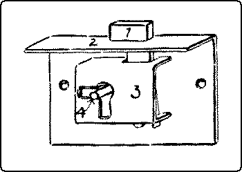
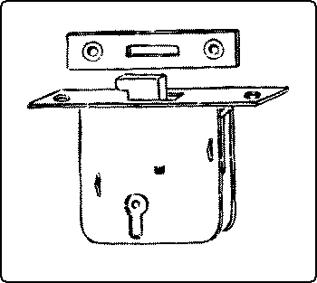
(2) According to the method of application, as rim locks, which are fastened on [page 134] the surface, and mortise locks which are mortised into the edge of a door or drawer or box.
To insert a rim-lock, measure the distance from the selvage to the key-pin, locate this as the center of the keyhole, and bore the hole. If the lock has a selvage, gain out the edge of the door or drawer to receive it. If the lock box has to be gained in, do that next, taking care that the bolt has room to slide. Cut the keyhole to the proper shape with a keyhole-saw or small chisel. Fasten the lock in place, and if there is a strike or face-plate, mark its place and mortise it in.
To insert a mortise-lock, locate and bore the keyhole, mortise in the box and the selvage, finish the keyhole, fasten in the lock, add the escutcheon, locate and mortise in the strike, and screw it in place.
[page 135]References*:
Hammacher & Schlemmer.
Catalog No. 151.
Nails.
Goss, p. 153.
Purfield, Wood Craft, 5: 181.
Park, pp. 129-135.
Griffith, pp. 75-78.
Wood Craft, 5: 103.
Wheeler, pp. 428-433.
Tacks.
Wheeler, pp. 429-433.
Sickels, p. 70.
Goss, p. 155.
Barter, pp. 84-86.
Screws.
Goss, p. 155.
Wheeler, p. 476.
Barter, p. 86.
Griffith, pp. 78-80.
Park, pp. 136-140.
Dowels.
Goss, p. 153.
Wheeler, p. 374.
Sickels, p. 104.
Griffith, p. 92.
Wedges.
Goss, p. 151.
Glue.
Goss, p. 156.
Rivington, III, p. 432.
Barter, p. 82.
Standage, Wood Craft, 7: 48.
Park, pp. 141-146.
Sickels, p. 106.
Wheeler, pp. 391-396.
Alexander, Wood Craft, 5: 168.
Griffith, pp. 80-83.
Hinges.
Sickels, p. 118.
Wheeler, p. 402.
* For general bibliography see p. 4.
[page 136]Tool equipment. The choice of tools in any particular shop best comes out of long experience. Some teachers prefer to emphasize certain processes or methods, others lay stress on different ones. The following tentative list is suggested for a full equipment for twenty-four students. One bench and its tools may be added for the teacher.
The prices given are quoted from Discount Sheet No. 1 for Catalogue of Tools, No. 355 issued by Hammacher, Schlemmer & Co., Fourth Avenue and 13th Street, New York City, dated 1908, and are correct at the present date (1910). Aggregate orders, however, are always subject to special concessions, and it is suggested that before ordering the purchaser submit a list of specifications for which special figures will be quoted.
There are good benches, vises, and tools of other makes on the market, but those specified below are typical good ones.
Following are two equipments for classes of twenty-four pupils, one severely economical to cost approximately $400, and the other more elaborate to cost approximately $750.
The general arrangement of the room. The important factors are the source or sources of light, and the lines of travel. The common arrangement of benches where two sides of the room are lighted, is shown in a, Fig. 238. By this arrangement, as each worker faces his bench, he also faces one set of windows and has another set of windows at his left. The advantage of this arrangement is that it is easy to test one's work with the try-square by lifting it up to the light. Another arrangement, shown in b, Fig. 238, has this advantage, that there are no shadows on the work when it is lying on the bench and the worker is holding his rule or try-square on it with his left hand. When all the windows are on one side of the room the latter is the more advantageous arrangement.
In determining the position of the benches, especially with reference to their distance from each other, thought should be given to the general lines of travel, from the individual benches to the general tool-rack, to the finishing-table, to the lockers, etc. Even if all the aisles cannot be wide enough both for passage and for work, one wider one thru the center of the room may solve the difficulty. Where [page 143] rooms are crowded, space may be economized by placing the benches in pairs, back to back, c and d, Fig. 238. In any case, room should always be reserved for a tier of demonstration seats, facing the teacher's bench, for the sake of making it easy for the pupils to listen and to think.
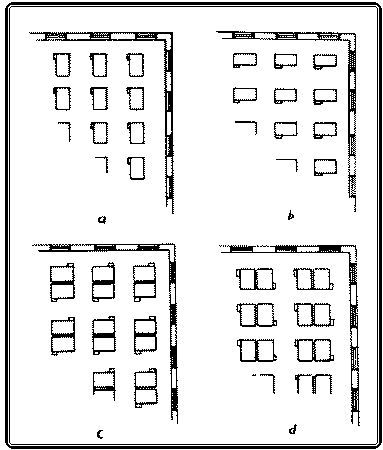
The Tools. Every shop soon has its own traditions as to the arrangement of tools, but there are two principles always worth observing. (1) It is an old saying that there should be "a place for everything and everything in its place." This is eminently true of a well-ordered woodworking shop, and there is another principle just as important. (2) Things of the same sort should be arranged together, and arranged by sizes, whether they be general tools or individual tools. In arranging the rack for general tools, a few suggestions are offered. In the first place, arrange them so that there will be no danger of cutting one's fingers on one tool when attempting to take down another. [page 144] Where the rack must needs be high, all the tools can be brought within reach, by placing long tools, like files, screwdrivers, etc., at the top. Such an arrangement is shown in Fig. 239.
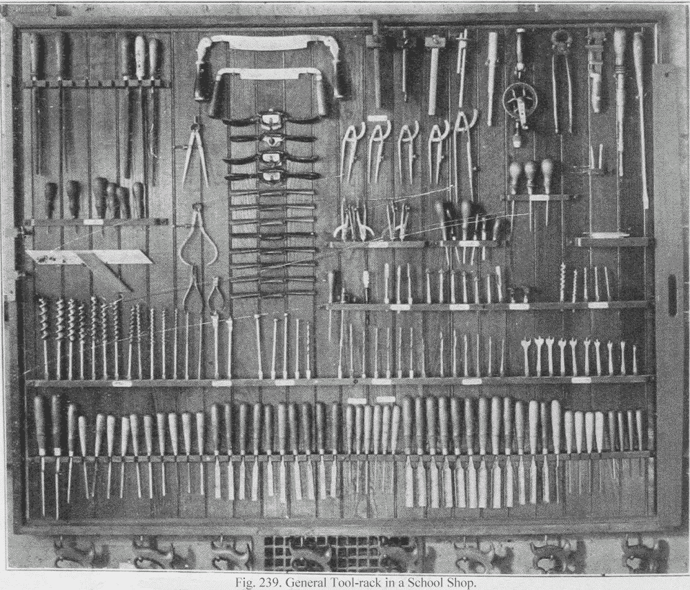
As to the individual benches, those without high backs are to be preferred, not only because of their convenience when it is desired to work on large pieces, like table tops, and because the backs do not interfere with the light, but because it is easier for the teacher to look over the room to see that everything is in order. If the equipment is kept complete, it is an easy matter to glance over all the benches and the general rack to see that everything is in place.
In general, there are two methods of keeping guard over tools, the open and the closed. In the open method, everything is kept in sight so that empty places can be discovered readily. This method is a convenient one, and, besides, the tools are always easily accessible. In the closed method, the tools are kept in drawers and cases where they can be locked up. This method is suitable where pupils are [page 145] equipped with individual sets of cutting tools. In such a case, the common tools for each bench are kept in a common drawer and individual pupils' tools in separate drawers. This method has the disadvantage that things are out of sight, and if they disappear their loss may not be discovered immediately. On the other hand, where the drawers and cases are kept carefully locked, the danger of loss is reduced almost to a minimum. Sometimes a combination of both methods is tried, the tools being kept in unlocked drawers. This method furnishes the greatest difficulty in keeping tools from disappearing.
Even when tools are well arranged, one of the most serious difficulties in the way of shop order, is to keep tools in their places. Pupils who are in a hurry, slip in the tools wherever they will fit, not where they belong. Labels at the places of the different sets may [page 146] help somewhat; a more efficient method is to paste or paint the form of each tool on the wall or board against which it hangs. Pupils will see that, when they will not stop to read a label.
In spite of all precautions, some tools will disappear. A plan to cover the cost of these, which works well in some schools, is to require a deposit at the beginning of the year to cover these losses. Then at the end of the year, after deducting the cost of losses, the balance is returned pro rata.
There is diversity of practice in the distribution of tools on the general case and on the individual benches. Some tools, like the [page 147] plane and chisel, and try-square, are so frequently in use that each worker must have one at hand. As to others, the demand must determine the supply. One other consideration may be expressed by the principle that those tools, the use of which is to be encouraged, should be kept as accessible as possible, and those whose use is to be discouraged, should be kept remote. Some tools, like files, it may be well to keep in a separate locker to be had only when asked for.
A cabinet of drawers, such as that shown in Fig. 240, for holding nails, screws, and other fastenings, is both a convenience and a material aid in preserving the order of the shop.
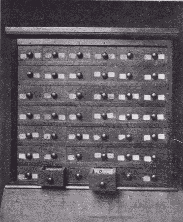
As for the care of tools during vacation, they should be smeared with vaseline, which is cheap, and put away out of the dampness. The planes should be taken apart and each part smeared. To clean them again for use, then becomes an easy matter. The best method of removing rust and tarnish is to polish the tools on a power buffing wheel on which has been rubbed some tripoli. They may then be polished on a clean buffer without tripoli.
The Lockers. In order to maintain good order in the shop, an almost indispensable part of the equipment is a set of lockers for holding [page 148] the unfinished work of pupils. An inexpensive outfit may consist simply of sets of shelves, say 5" apart, 12" deep, and 18" long, Fig. 241. Ordinary spring-roller curtains may be hung in front of each set of shelves to conceal and protect the contents. Such a case should cost at the rate of about 40c. for each compartment. A more substantial and more convenient case, shown in Fig. 242, consists of compartments each 9½" high, 6" wide, and 18" deep. These proportions may be changed to suit varying conditions. In front of each tier of 12 compartments is a flap door opening downward. Such a case built of yellow pine (paneled) may cost at the rate of $1.00 per compartment.
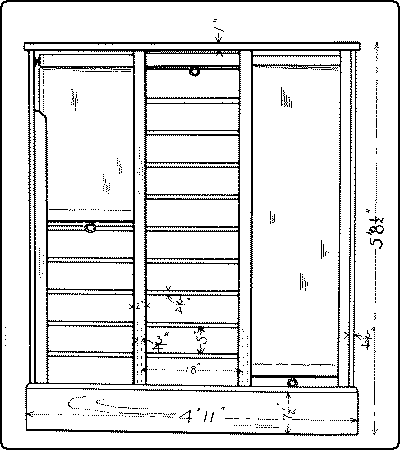
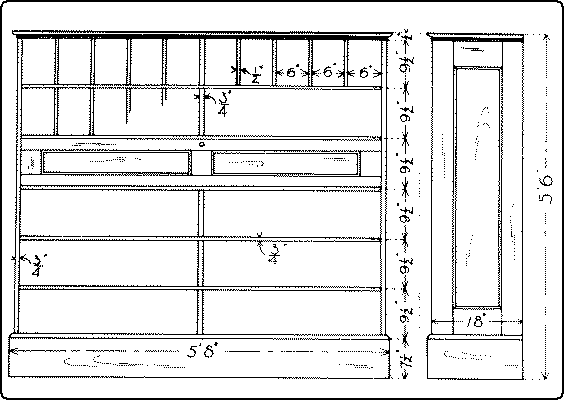
There should, of course, be a separate compartment for each pupil using the shop. Where possible, there should be a special table [page 149] for staining and gluing. Where strict economy must be practiced, a good sized kitchen table covered with oilcloth answers every purpose. A better equipment would include a well-built bench, such as that shown in Fig. 243, the top and back of which are covered with zinc.
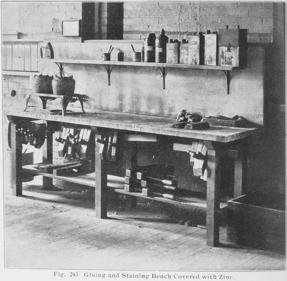
Where no staining-table is possible, temporary coverings of oilcloth may be provided to lay over any bench which is convenient for the purpose.
Care of brushes and materials used in finishing wood. Shellac should be kept in glass or pottery or aluminum receptacles but not in any metal like tin, which darkens it. A good plan is to have a bottle for fresh, untouched shellac, a wide-mouthed jar for that which has been diluted and used, and an enameled cup for use. There should also be a special brush, Fig. 244. At the time of using, first see that the brush is soft and pliable. If it is stiff, it can be soaked quickly and softened in a little alcohol in the cup. This alcohol may then be poured into the jar and mixed in by shaking. Then pour out a little from the jar into the cup, and if it is too thin, thicken with some fresh shellac. After using, pour back the residue into the jar, carefully wiping the brush on the edge of the jar; and if it is not to be used again for some time, rinse it in a little alcohol, which may also be poured into the jar, which should then be covered. What little shellac remains in the brush and cup will do no harm and the brush may be left standing in the cup until required. The important things are to keep the shellac cup and brush for shellac only, (indeed, it is a good plan to label them "SHELLAC ONLY,") and to keep the shellac covered so that the alcohol in it will not evaporate. In a pattern-making shop, where the shellac cup is to be frequently used, it is well to have cups with covers thru which the brushes hang, like the brush in a mucilage jar.
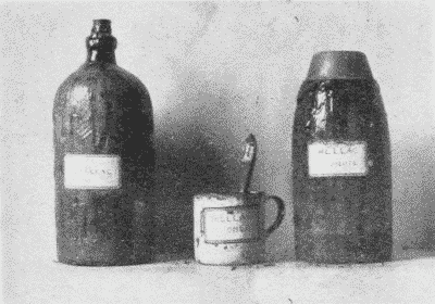
Varnish brushes need to be cleaned thoroly after each using. If they get dry they become too hard to be cleaned without great difficulty.
[page 150]Brushes for water stains are easily taken care of by washing with water and then laying them flat in a box. Cups in which the water stains have been used can also be easily rinsed with water.
Brushes for oil stains are most easily kept in good condition, by being hung in a brush-keeper, Fig. 245, (sold by Devoe & Reynolds, 101 Fulton St., N. Y. C.) partly filled with turpentine. The same brushes may also be used for fillers.
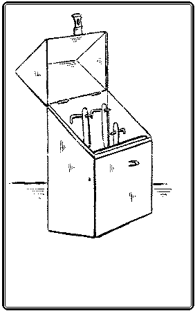
Oil stains should be poured back into their respective bottles, and the cups wiped out with cotton waste. When they get in bad condition, they can be cleaned readily after a preliminary soaking in a strong solution of potash. The same treatment may be given to brushes, but if they are left soaking too long in the solution, the bristles will be eaten off.
References*
Murray, Year Book 1906, p. 69.
Bailey, M. T. Mag., 9: 138. Dec. '07.
Robillion, pp. 48-90.
Hammacher and Schlemmer, passim.
* For general bibliography, see p. 4.
[page 151]Wherever two or more pieces of wood are fastened together we have what is properly called joinery. In common usage the term indicates the framing of the interior wood finish of buildings and ships, but it is also used to include cabinet-making, which is the art of constructing furniture, and even the trades of the wheelwright, carriage-maker, and cooper. Since joinery involves the constant use of joints, a reference list of them, with illustrations, definitions, uses, and directions for making typical ones may be of convenience to workers in wood.
No. 1. A lapped and strapped joint is made by laying the end of one timber over another and fastening them both together with bent straps on the ends of which are screws by which they may be tightened. It is a very strong joint and is used where the beams need lengthening as in false work or in long ladders and flag poles.
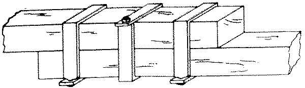
No. 2. A fished joint is made by butting the squared ends of two timbers together and placing short pieces of wood or iron, called fish-plates, over the faces of the timbers and bolting or spiking the whole firmly together. It is used for joining timbers in the direction of their length, as in boat construction.
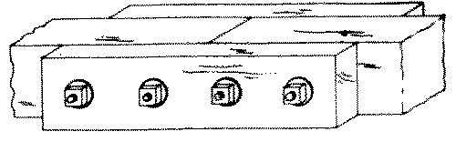
No 3. In a fished joint keys are often inserted between the fish-plate and beam at right angles to the bolts in order to lessen the strain that comes upon the bolts when the joint is subjected to tension. In wide pieces and for extra strength, as in bridge work, the bolts may be staggered.
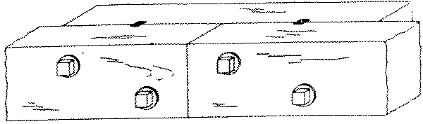
Nos. 4, 5, 6 and 7. A scarf or spliced joint is made by joining together with flush surfaces the ends of two timbers in such a way as to enable them to resist compression, as in No. 4; tension, as in No. 5; both, as in No. 6, where the scarf is tabled; or cross [page 152] strain as in No. 7. No. 4 is used in house sills and in splicing out short posts, Nos. 5 and 6 in open frame work. No. 7 with or without the fish-plate, is used in boats and canoes, and is sometimes called a boat-builder's joint, to distinguish it from No. 4, a carpenter's joint. A joint to resist cross strain is stronger when scarfed in the direction of the strain than across it. No. 7 is the plan, not elevation, of a joint to receive vertical cross strain.
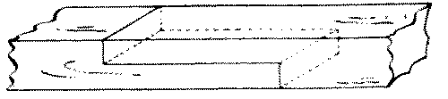
No. 8. A doweled butt-joint is made by inserting, with glue, dowel-pins into holes bored into the two members. The end of one member is butted against the face or edge of the other. It is used in cabinet-making where the presence of nails would be unseemly.
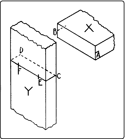
In a doweled butt-joint the dowels may go clear thru the outside member, and be finished as buttons on the outside, where they show. To lay out this joint mark near the ends of the edges of the abutting member, X, Fig. 246, center-lines A B. Draw on the other member Y, a sharp pencil-line to which when the lines AB on X are fitted, X will be in its proper place. Carry the line around to the other side of Y and locate on it the proper centers for the dowel-holes E and F. Then fasten on the end of X a handscrew in such a way that the jaws will be flush with the end. With another handscrew, clamp this handscrew to Y in such a way that the marks on the two pieces match, A to C and B to D, Fig. 247. Bore at the proper places, E and F, holes directly thru Y into X.
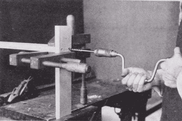
Fig. 248 illustrates the gluing together of a four-legged stand in which the joints are made in this way. The cross-lap joints of the stretchers are first glued together, then the other joints are assembled without glue, to see that all the parts fit and finally two opposite [page 153] sides are glued at a time. Pieces of paper are laid inside the gluing blocks to prevent them from sticking to the legs.
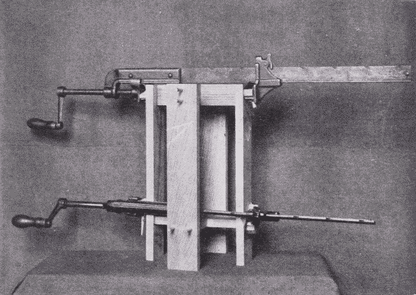
In case the dowels are to be hidden the chief difficulty is to locate the holes properly. One method of procedure is as follows: To dowel the end of one member against the face of the other as a stringer into a rail or a rail into a table leg, first lay out the position of the dowels in the end of the first member, X, Fig. 249. Gage a center-line, A B, across this end lengthwise, locate the centers of the dowel-holes, and square across with a knife point, as CD and EF. Gage a line on the other member to correspond with the line AB. On the face so gaged, lay the first member on its side so that one arris lies along this gaged line and prick off the points D and F, to get the centers of the dowel-holes.
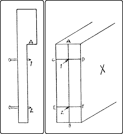
If, as is usual, there are a number of similar joints to be made, a device like that shown in Fig. 249 will expedite matters. 1 and 2 are points of brads driven thru a piece of soft wood, which has been notched out, and are as far apart as the dowels. A-1 is the distance from the working edge of the rail to the first dowel. The same measure can be used from the end of the leg.
When the centers are all marked, bore the holes. Insert the dowels into the holes and make a trial assembly. If any rail is twisted from its proper plane, note carefully where the error is, take apart, glue a dowel into the hole, that is wrong, pare it off flush with the surface, and re-bore in such a place that the parts, when assembled will come up true. When everything fits, glue and clamp together.
No. 9. A toe-nailed joint is made by driving nails diagonally thru the corners of one member into the other. It is used in fastening the studding to the sill in balloon framing.
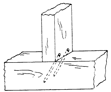
No. 10. A draw-bolt joint is made by inserting an iron bolt thru a hole in one member and into the other to meet a nut [page 155] inserted from the side of the second member. It is very strong and is used in bench construction, wooden machinery, etc.
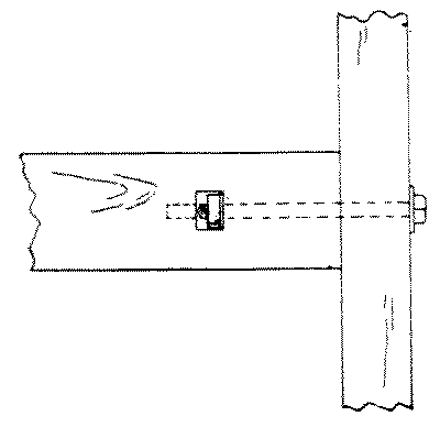
No. 11. A plain butt-joint is one in which the members join endwise or edgewise without overlapping. It is used on returns as in ordinary boxes and cases.
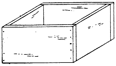
No. 12. A glued and blocked joint is made by gluing and rubbing a block in the inside corner of two pieces which are butted and glued together. It is used in stair-work and cabinet-work, as in the corners of bureaus.
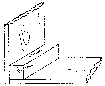
No. 13. A hopper-joint is a butt-joint, but is peculiar in that the edges of the boards are not square with their faces on account of the pitch of the sides. It is used in hoppers, bins, chutes, etc. The difficulty in laying out this joint is to obtain the proper angle for the edges of the pieces. This may be done as follows: After the pieces are planed to the correct thickness, plane the upper and lower edges of the end pieces to the correct bevel as shown by the pitch of the sides. Lay out the pitch of the sides of the hopper on the outside of the end pieces. From the ends of these lines, on the upper and lower beveled edges score lines at right angles with the knife and try-square. Connect these lines on what will be the inside of the hopper. Saw off the surplus wood and plane to the lines thus scored. The side pieces may be finished in the same way, and the parts are then ready to be assembled.
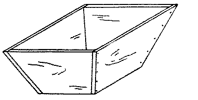
A halved joint is one in which half the thickness of each member is notched out and the remaining portion of one just fits into the notch in the other, so that the upper and under surfaces of the members are flush.
No. 14. A cross-lap joint is a halved joint in which both members project both ways from the joint. This is a very common joint used in both carpentry and joinery, as where stringers cross each other in the same plane.
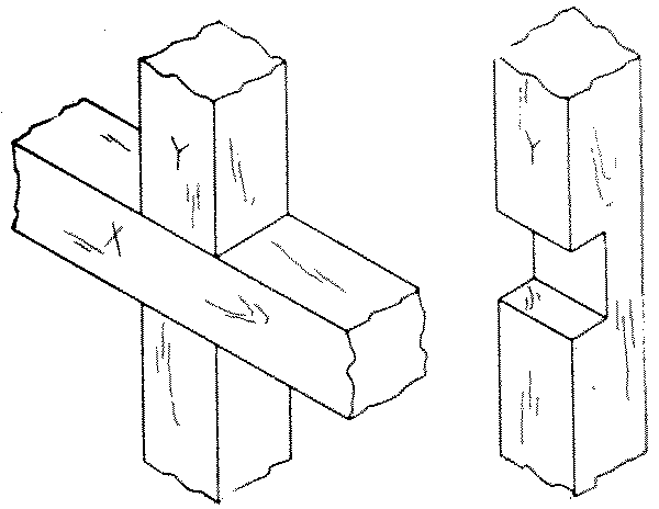
The two pieces are first dressed exactly to the required size, either separately or by the method of making duplicate parts, see Chap. IX, p. 204. Lay one member, called X, across the other in the position which they are to occupy when finished and mark plainly their upper faces, which will be flush when the piece is finished. Locate the middle of the length of the lower piece, called Y, on one [page 156] arris, and from this point lay off on this arris half the width of the upper piece, X. From this point square across Y with the knife and try-square. Lay X again in its place, exactly along the line just scored. Then mark with the knife on Y the width of X, which may then be removed and the second line squared across Y. From these two lines square across both edges of Y to approximately one-half the thickness. Now turn X face down, lay Y on it, and mark it in the same way as Y. Set the gage at one-half the thickness of the pieces, and gage between the lines on the edges, taking care to hold the head of the gage against the marked faces. Then even if one piece is gaged so as to be cut a little too deep, the other will be gaged so as to be cut proportionately less, and the joint will fit.
Cut a slight triangular groove on the waste side of the knife-marks, Fig. 91, p. 66, saw accurately to the gaged lines, and chisel out the waste as in a dado, see Figs. 70 and 71, p. 56.
The bottom of the dado thus cut should be flat so as to afford surface for gluing. When well made, a cross-lap joint does not need to be pounded together but will fit tight under pressure of the hands.
No. 15. A middle-lap joint or halved tee is made in the same way as a cross-lap joint, but one member projects from the joint in only one direction, it is used to join stretchers to rails as in floor timbers.
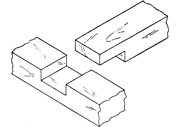
No. 16. An end-lap joint is made in the same way as a cross-lap joint except that the joint is at the end of both members. It is used at the corners of sills and plates, also sometimes in chair-seats.
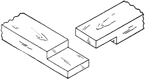
To make an end-lap joint, place the members in their relative positions, faces up, and mark plainly. Mark carefully on each member the inside corner, allowing the end of each member slightly (1⁄16") to overlap the other. Square across at these points with a sharp knife point, on the under side of the upper member, and on the upper side of the lower member. Now proceed as in the cross-lap joint, except that the gaged line runs around the end and the cutting must be done exactly to this line.
No. 17. In an end-lap joint on rabbeted pieces the joint must be adapted to the rabbet. The rabbet should therefore be plowed before the joint is made. The rabbet at the end of the piece X is cut not the entire width of the piece Y, but only the width of the lap,—c-f = a-e. This joint is used occasionally in picture-frames.
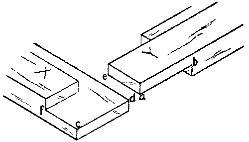
No. 18. A dovetail halving or lap-dovetail is a middle-lap joint with the pin made dovetail in shape, and is thus better able to resist tension. It is used for strong tee joints.
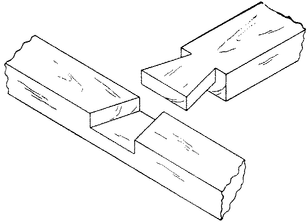
No. 19. A beveled halving is made like a middle-lap joint except that the inner end of the upper member is thinner so that the adjoining cheeks are beveled. It is very strong when loaded above. It was formerly used in house framing.
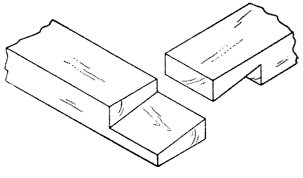
No. 20. A notched joint is made by cutting out a portion of one timber. It is used where it is desired to reduce the height occupied by the upper timber. Joists are notched on to wall plates.
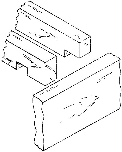
No. 21. A checked joint or double notch is made by cutting out notches from both the timbers so as to engage each other. It is used where a single notch would weaken one member too much.
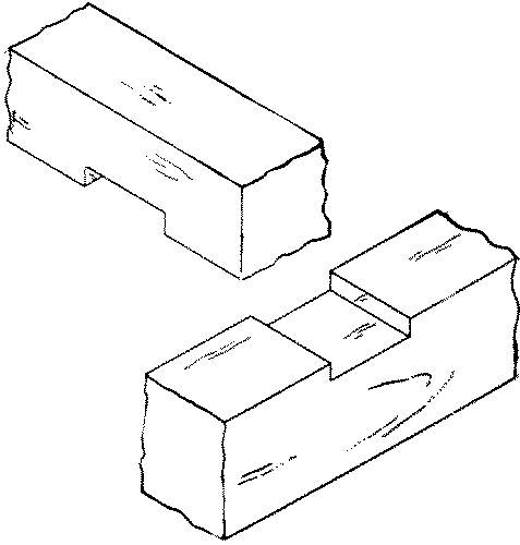
No. 22. A cogged or corked or caulked joint is made by cutting out only parts of the notch on the lower piece, leaving a "cog" uncut. From the upper piece a notch is cut only wide enough to receive the cog. A cogged joint is stronger than a notched because the upper beam is not weakened at its point of support. It is used in heavy framing.
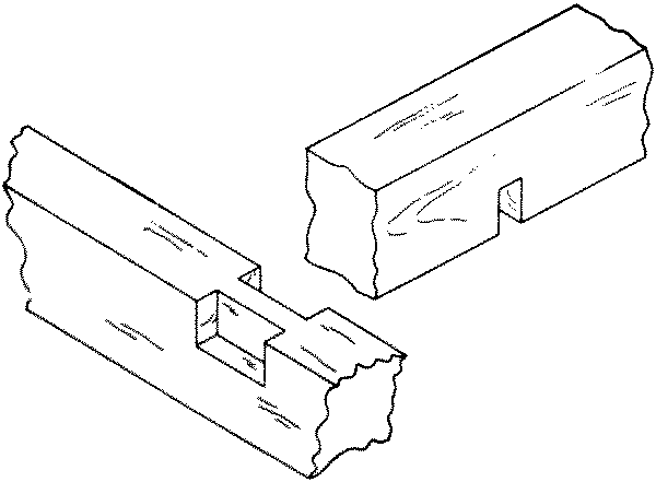
No. 23. A forked tenon joint is made by cutting a fork in the end of one member, and notching the other member to fit into the fork, so that neither piece can slip. It is used in knock-down furniture and in connecting a muntin to a rail, where it is desired that the muntin should run thru and also that the rail be continuous.
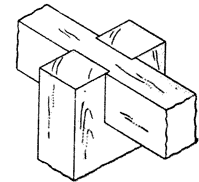
No. 24. A rabbet or rebate or ledge joint is made by cutting out a portion of the side or end of a board or timber X to receive the end or side of another, Y. It may then be nailed from either the side or end or from both. The neatest way in small boxes is from the end, or better still it may be only glued.
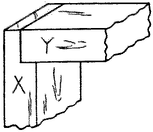
No. 25. A dado or grooved joint is made by cutting in one member a groove into which the end or edge of the other member fits. Properly speaking a groove runs with the grain, a dado across it, so that the bottom of a drawer is inserted in a groove while the back of the drawer is inserted in a dado. Where the whole [page 158] of the end of one member is let into the other, such a dado is also called a housed dado. Treads of stairs are housed into string boards.
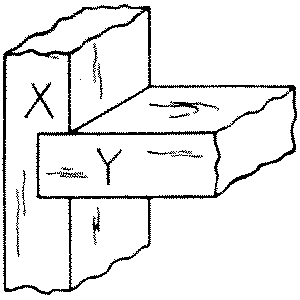
To lay out a dado joint: After carefully dressing up both pieces to be joined, locate accurately with a knife point, on the member to be dadoed, called X, one side of the dado, and square across the piece with a try-square and knife. Then locate the other side of the dado by placing, if possible, the proper part of the other member, called Y, close to the line drawn. If this method of superposition is not possible, locate by measurement. Mark, with a knife point, on X, the thickness thus obtained. Square both these lines as far across the edges of X as Y is to be inserted. Gage to the required depth on both edges with the marking-gage.
To cut the joint: First make with the knife a triangular groove on the waste side of each line, as indicated in Fig. 91, p. 66, and starting in the grooves thus made, saw with the back-saw to the gaged lines on both edges. The waste may now be taken out either with a chisel or with a router, Fig. 122, p. 83. The second member, Y, should just fit into a dado thus made, but if the joint is too tight, the cheeks of the dado may be pared with a chisel. In delicate work it is often wise not to saw at all, but to use only the knife and chisel.
No. 26. A dado and rabbet is made by cutting a dado in one member, X, and a rabbet on the other, Y, in such a way that the projecting parts of both members will fit tight in the returns of the other member. It is used in boxes and gives plenty of surface for gluing.
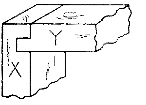
No. 27. A dado, tongue and rabbet is a compound joint, made by cutting a rabbet on one member, Y, and then a dado in this rabbet, into which fits a tongue of the other member, X. It is used in machine-made drawers.
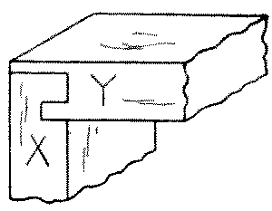
No. 28. A dovetail dado or gain is made by cutting one or both of the sides of the infitting member, Y, on an angle so that it has to be slid into place and cannot be pulled out sidewise. It is used in book-cases and similar work, in which the shelves are fixed.
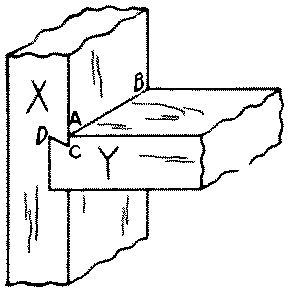
To make this joint, first lay out the dovetail on the member to be inserted, called Y, thus: Across one end square a line (A B, No. 28), at the depth to which this member is to be dadoed in. Set the bevel-square at the proper angle for a dovetail, Fig. 250. Score this angle on the edges of the member, as at C D. Cut a groove with [page 159] a knife on the waste side of A B. Saw to the depth A C, and chisel out the interior angle A C D.
Then lay out the other member, X, thus: mark with the knife the proper place for the flat side of Y, square this line across the face and on the edges as for a simple dado. Lay out the thickness of Y on the face of X by superposition or otherwise and square the face and edges, not with a knife but with a sharp pencil point. Gage the required depth on the edges. Now with the bevel-square as already set, lay out the angle A C D on the edges of X, and across the face at C score a line with knife and try-square. Cut out grooves in the waste for the saw as in a simple dado, and saw to the proper depth and at the proper angle. Chisel or rout out the waste and when complete, fit the pieces together.
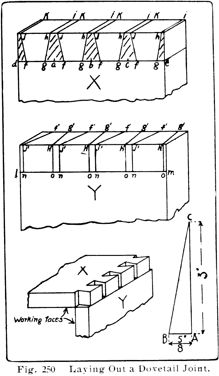
No. 29. A gain joint is a dado which runs only partly across one member, X. In order to make the edges of both members flush and to conceal the blind end of the gain, the corner of the other member, Y, is correspondingly notched out. In book shelves a gain gives a better appearance than a dado.
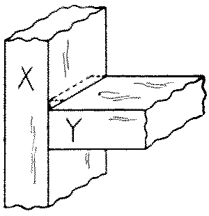
A gain joint is laid out in the same way as the dado, except that the lines are not carried clear across the face of X, and only one edge is squared and gaged to the required depth. Knife grooves are made in the waste for starting the saw as in the dado. Before sawing, the blind end of the gain is to be chiseled out for a little space so as to give play for the back-saw in cutting down to the required depth. To avoid sawing too deep at the blind end, the sawing and chiseling out of waste may be carried on alternately, a little at a [page 160] time, till the required depth is reached. It is easy to measure the depth of the cut by means of a small nail projecting the proper amount from a trial stick, Fig. 251. The use of the router, Fig. 122, p. 83, facilitates the cutting, and insures an even depth.
The tenon in its simplest form is made by dividing the end of a piece of wood into three parts and cutting out rectangular pieces on both sides of the part left in the middle. The mortise is the rectangular hole cut to receive the tenon and is made slightly deeper than the tenon is long. The sides of the tenon and of the mortise are called "cheeks" and the "shoulders" of the tenon are the parts abutting against the mortised piece.
No. 30. A stub mortise-and-tenon is made by cutting only two sides of the tenon beam. It was formerly used for lower ends of studding or other upright pieces to prevent lateral motion.
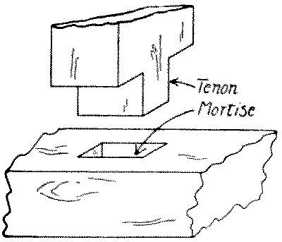
No. 31. A thru mortise-and-tenon is made by cutting the mortise clear thru one member and by cutting the depth of the tenon equal to or more than the thickness of the mortised member. The cheeks of the tenon may be cut on two or four sides. It is used in window sashes.
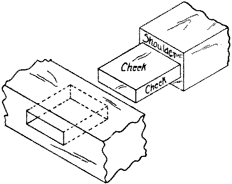
A thru mortise-and-tenon joint is made in the same way as a blind mortise-and-tenon (see below), except that the mortise is laid out on the two opposite surfaces, and the boring and cutting are done from both, cutting first from one side and then from the other.
No. 32. A blind mortise-and-tenon is similar to the simple mortise-and-tenon described in 30. The tenon does not extend thru the mortised member and the cheeks of the tenon may be cut on two or four sides.
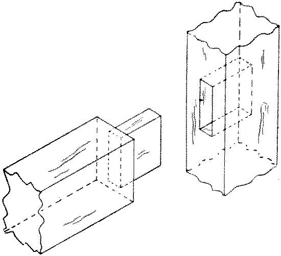
To make a blind mortise-and-tenon, first make the tenon thus: Locate accurately with a knife point the shoulders of the tenon and square entirely around the piece. On the working edge near the end mark the thickness of the tenon. Set the marking-gage at the proper distance from the working face to one cheek of the tenon and gage the end and the two edges between the end and the knife-lines. Reset the gage to mark the thickness of the tenon and gage that in the same way from the working face. Then mark and gage the width of the [page 161] tenon in the same way. Whenever there are several tenons of the same size to be cut, they should all be laid out together, that is the marking-gage set once to mark all face cheeks and once to mark all back cheeks. If a mortise-gage is available, use that. Always mark from the working face or working edge. Cut out a triangular groove on the waste side of the knife lines (at the shoulders) as in cutting a dado, Fig. 91, p. 66.
In cutting the tenon, first rip-saw just outside the gaged lines, then crosscut at the shoulder lines. Do all the rip-sawing before the crosscutting. If the pieces are small the back-saw may be used for all cuts. It is well to chamfer the arrises at the end of the tenon to insure its starting easily into the mortise.
Locate the ends of the mortise and square lines across with a sharp pencil in order to avoid leaving knife marks on the finished piece. Then locate the sides of the mortise from the thickness of the tenon, already determined, and gage between the cross lines. As in the case of like tenons, if there are a number of mortises all alike, set the gage only twice for them all.
In cutting the mortice, first fasten the piece so that it will rest solid on the bench. This may be done either in a tail vise or by a handscrew, or by clamping the bench-hook firmly in the vise in such a way that the cleat of the bench-hook overhangs the piece. Then tap the bench-hook with a mallet and the piece will be found to be held tightly down on the bench. See Fig. 76, p. 58.
It is common to loosen up the wood by first boring a series of adjoining holes whose centers follow the center-line of the mortise and whose diameter is slightly less than the width of the mortise. Take care to bore perpendicularly to the surface, see Fig. 137, p. 86, and no deeper than necessary. Dig out the portions of wood between the auger holes and chisel off thin slices, back to the gage-lines and to the knife-lines, taking care all the time to keep the sides of the mortise perpendicular to the face. This may be tested by placing the chisel against the side of the mortise and standing alongside it a try-square with its head resting on the surface.
Finally test the tenon in the mortise noting carefully where it pinches, if anywhere, and trim carefully. The tighter it fits without danger of splitting the mortised member, the stronger will be the joint.
Many prefer to dig mortises without first boring holes. For this purpose a mortise-chisel, Fig. 68, p. 54, is desirable. The method is [page 162] to begin at the middle of the mortise, placing the chisel—which should be as wide as the mortise—at right angles to the grain of the wood. Chisel out a V shaped opening about as deep as the mortise, and then from this hole work back to each end, occasionally prying out the chips. Work with the flat side of the chisel toward the middle except the last cut or two at the ends of the mortise.
No. 33. In a mortise-and-tenon joint on rabbeted pieces, Fig. 266, the tenon is as much shorter on one side than the other as the rabbet is wide. In Fig. 33, ab = cd.
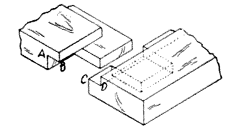
No. 34. A wedged mortise-and-tenon joint is a thru joint in which after the tenon is driven home, wedges are driven in between the tenon and the sides of the mortise. The wedges are dipped in glue or white lead before being inserted. The sides of the mortise may be slightly dovetailed. It is used to keep a tenon tightly fixed as in wheel spokes.
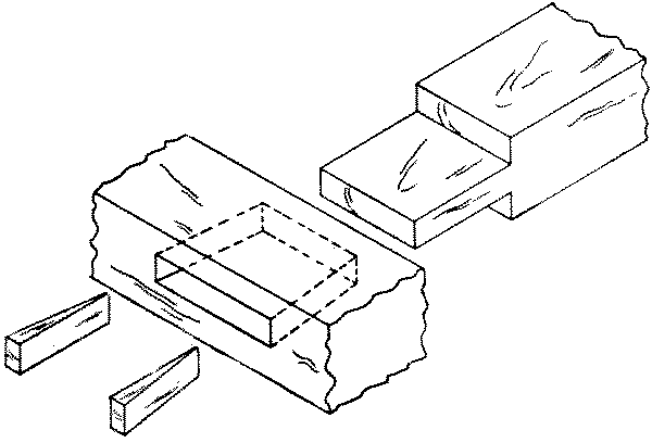
No. 35. A wedged mortise-and-tenon joint may also be made by driving the wedges into saw kerfs in the tenon instead of along its sides as in No. 34. It is used in ornamental joints as well as in carpentry.
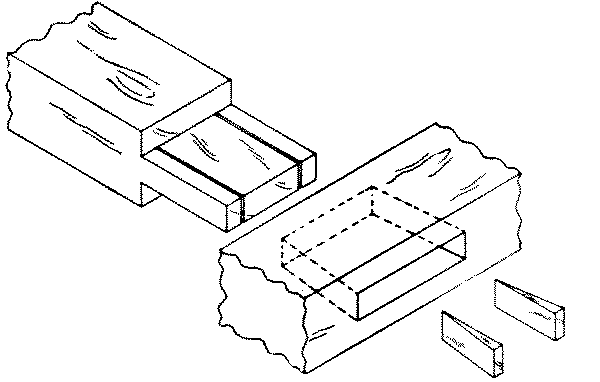
No. 36. A fox-tail tenon is a blind mortise-and-tenon in which the mortise is made slightly wider at the bottom than the width of the tenon. Wedges are driven into saw kerfs in the tenon before inserting into the mortise; then when it is driven home the wedges spread out the tenon and make it fill out the mortise. It is used in strong doors and also where the mortised member is already in place so that a wedged mortise-and-tenon is impossible.
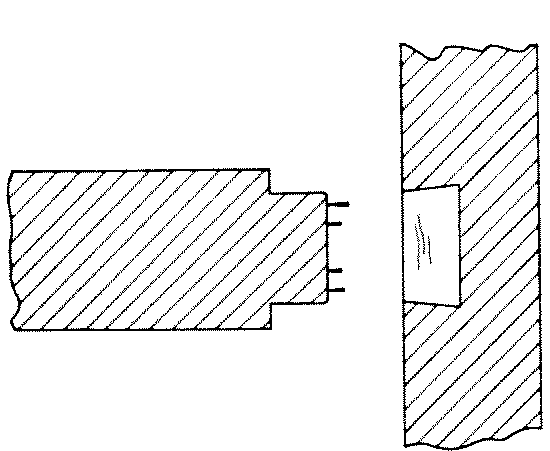
No. 37. A dovetail mortise-and-tenon is a thru mortise-and-tenon beveled on one side so as to form half a dovetail. The corresponding side of the mortise is also beveled and made wide enough so that when the tenon is pressed well up against its beveled side a wedge may be driven into the space left on the straight side. It is used to tenon a beam into a post especially where the post is fixed against a wall. It is also used in machinery frames which are made of wood.
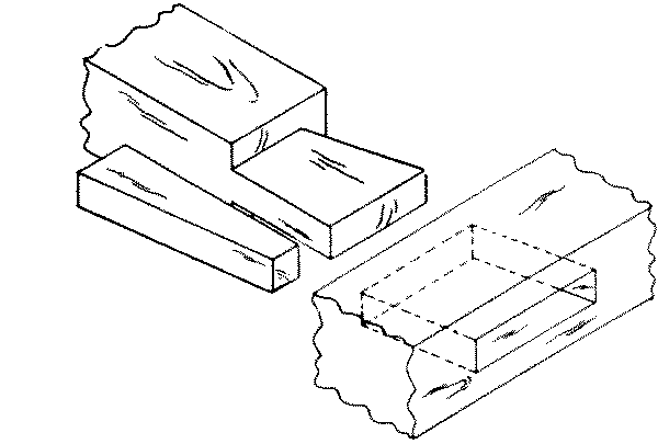
No. 38. A pinned mortise-and-tenon is one in which a pin is driven thru holes bored thru the mortised beam and thru the tenon to keep them from drawing apart. It is used in heavy framing as in bridges, in wagon-making, in window-sash, etc.
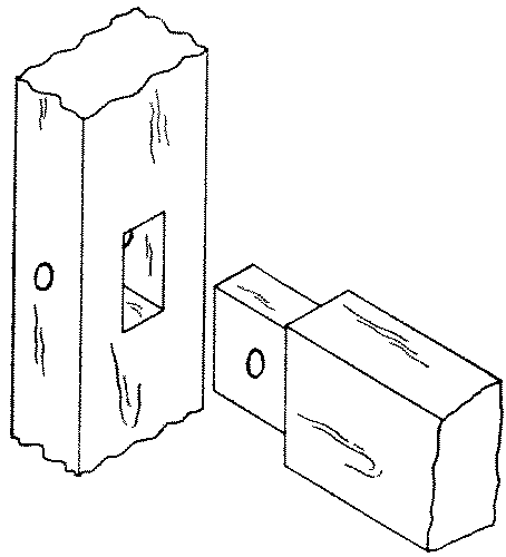
No. 39. A keyed mortise-and-tenon is one in which the tenon protrudes thru the mortise far enough to receive a removable key and thus be drawn up tight to the mortised member. It is used in work-benches and in ornamental joints like knock-down bookcases and in other mission furniture.
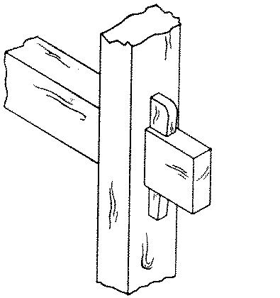
The keyed mortise-and-tenon is made as in a thru mortise-and-tenon, except that before cutting the tenons the holes for wedges should be laid out thus: measuring from the shoulder of the tenon, locate by superposition or measurement the outside of the mortised member. Deduct from this 1⁄16" and square a fine pencil-line across the face and opposite side. This line will be the inside of the hole for the wedge, and the 1⁄16" is deducted to make sure that the key wedges against the mortised member. On the upper surface of the tenon, lay off toward the end the width of the wedge at this point, A B, Fig. 252, and square across. On the under surface, lay off the width of the wedge at this point, C D, and square across.
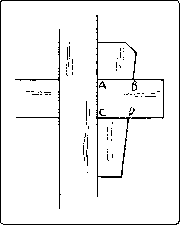
Gage the sides of the wedge hole on both upper and lower surfaces of the tenon. After cutting the mortise and tenon, bore and chisel out the hole for the wedge, taking care to cut the side toward the end on a bevel to fit the wedge.
No. 40. A tusk tenon or shoulder tenon is one in which the tenon proper is quite thin but is reinforced by a thicker shoulder called a "tusk." The upper shoulder is beveled. The object of this form is to weaken the mortised member as little as possible but at the same time to increase the strength of the tenon. It is used in joining tail beams to headers in floor framing.
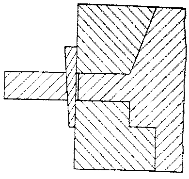
No. 41. A double mortise-and-tenon consists of two tenons side by side in one piece fitting into two corresponding mortises. It is used in joinery, as in door-frames, but not in carpentry.
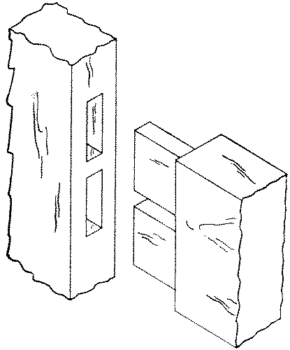
No. 42. A haunched mortise-and-tenon is made by cutting away part of the tenon so that that part of it will be much shorter than the rest. The haunch gives the tenon great lateral [page 164] strength and saves cutting so large a mortise hole. It is used in panel construction, as where the rails are joined to the stiles of doors.
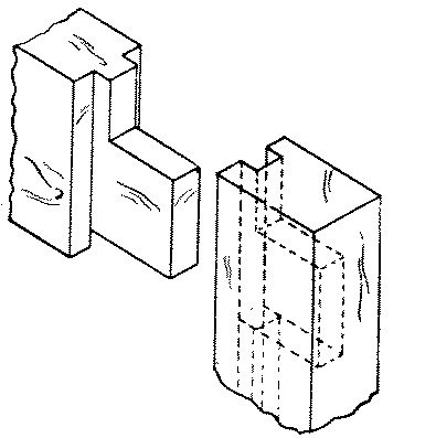
First plow the groove in all the members. This should be of the same width as the thickness of the tenons, which is ordinarily one-third of the thickness of the frame. The groove is approximately as deep as it is wide. Lay out and cut the tenon the width of the entire piece, minus, of course, the depth of the groove. The mortise should not come too near the end, or the portion of wood outside it will shear out. Hence the tenon is narrowed on the outside enough to insure strength in the mortised piece. The rule is that the tenon should be one-half the width of the rail, minus the groove. But enough of the tenon is left full width to fill up the groove at the outer end of the mortised piece. This is called the haunch. The width of the mortise is equal to the width of the groove, its length to the width of the tenon. Before assembling the panel frame, put soap or tallow on the corners of the panel to prevent its being glued to the frame.
No. 43. Table or taper haunching. Sometimes, as in table construction, for the sake of stiffening the rail, or in places where it is desirable that the haunch does not show, the haunch is beveled from the tenon to the edge of the rail.
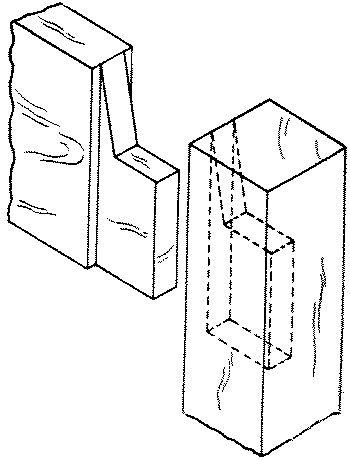
No. 44. A bare-faced tenon is one in which a cheek is cut from only one side. It is used where the rail is thinner than the stile and it is desirable to keep the mortise near the middle of the stile.
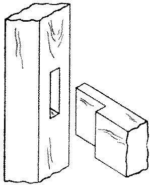
No. 45. A housed mortise-and-tenon is one in which the whole of the end of one member is let in for a short distance or "housed" into the other. It is common in grill work and in railings.
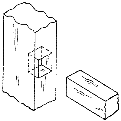
No. 46. A slip-joint or end or open mortise-and-tenon is what would remain if a mortised member were sawn off along one side of the tenoned member. Window screens and other light frames such as those for slates and for printing photographs have this joint. This joint multiplied is used for small machine-made boxes, and is then called corner locking.
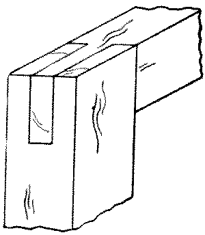
"Dovetail" refers to the shape of the projections of one member, when looked at broadside. These projections are called dovetails, or merely tails.
[page 165]The projections on the other member are called tenons or pins, and the spaces between both tails and tenons are called mortises or sockets.
No. 47. A thru single dovetail is similar to a slip-joint except that instead of a tenon there is a dovetail. It is used in window-sashes.
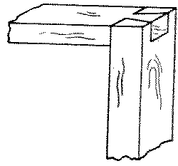
No. 48. A thru-multiple dovetail consists of a series of alternate tails and tenons which fit one another closely. It is used in tool-chests and in other strong as well as fine boxes.
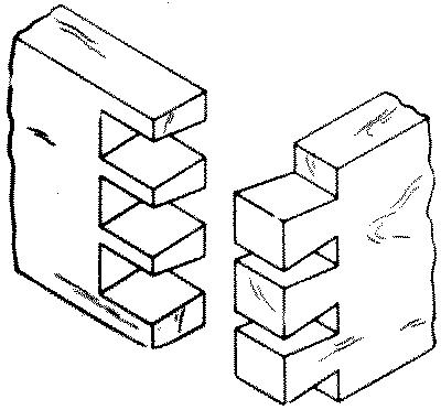
To make a thru multiple dovetail joint, first square lines with a sharp pencil around the ends of both members to locate the inner ends of the dovetails and the pins, d e on X, Fig. 250, and l m on Y. The distance of this line from the ends of each member may, if desired, be slightly (1⁄32") greater than the thickness of the other member. Divide this line, d e, on the member to be dovetailed, X, into as many equal spaces as there are to be tails (dovetails). From the division points of these spaces, a b c, to the right and left lay off one-half of the greatest width of the mortises to be cut out, and also the same distance from d and from e, as at f f f f and g g g g.
The strongest arrangement of dovetails is to make them equal in width to the spaces between them, as in No. 48, p. 165. For the sake of appearance they may be as much as four times as wide as the spaces, but ordinarily should not be wider than 1¾".
Set the bevel-square so that it will fit the angle A B C, Fig. 250, p. 159, in a right angle triangle, the long side of which is 3" and the short side ⅝". This is approximately an angle of 80° or a little more than one to five. From the points f f f f and g g g g lay off this angle to the end of the piece. Carry these lines across the end at right angles to the surface, h i, Fig. 250, and repeat the dovetail angles on the other surface. Mark plainly the parts to be cut out (the mortises), as on X in Fig. 250. Score with a knife point the inner ends of the mortises, d to f, g to f, etc., and across the edge at d and at e. With a dovetail-saw, Fig. 93, p. 67, cut on the mortise side of each line down to the cross line, d-e, and also along the cross line from d to f and e to g. Chisel out the mortises taking care to keep the line d-e straight and square. The ends (not the sides) of the mortises may be slightly undercut to insure a tight fit.
Fasten the other member, Y, upright in the vise so that the end to be tenoned will be flush with the top of the bench, and with the working [page 166] face toward the bench. Place on it the working face of X, (the member already dovetailed,) taking care that the inner ends of the mortises are in line with the working face of Y, and that the edges of the two members are in the same plane, as X on Y in Fig. 250. Scribe with a knife point along the sides of the tails on the end of Y (f'-j' and g'-h'). Remove Y from the vise and square down these lines to the cross line l-m (j'-n and h'-o). Score with the knife point the inner ends of the mortises of Y (n-o). Saw with a dovetail-saw on the mortise sides of these lines, chisel out the mortises and fit the parts together. When glued together, the joints should be dressed off.
Where there are several parts to be made alike, it is necessary to lay out the dovetails on only one X member. This may be used as a templet for laying out the others and they can then be sawn separately. Or all the X members may be clamped carefully together, with one X already laid out, rights and lefts in pairs, and edges and ends flush, the depth mark gaged all around, and then all sawn at once.
The dovetail joint is also made by first laying out and cutting the members having the pins, and then superposing this on the piece to be dovetailed, and scribing around the pins.
No. 49. A lap or half blind dovetail is a dovetail joint in which the tails on one member do not extend entirely thru the thickness of the other member. It is used in joining the sides to the fronts of drawers and other fittings where only one side is seen.
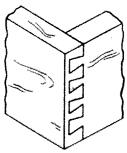
If the joint is to be used for a drawer front, the groove for the drawer bottom should be cut or at least laid out before laying out the joint. See also drawers, p. 190, and Fig. 287, p. 191. On the end of the drawer front, gage the depth of the joint. Gage the same distance on both broad surfaces of the drawer sides, marking from the front ends. Lay out and cut the dovetails as in a thru dovetail joint, taking especial care to have the groove for the bottom completely within the lower tail. Take care also to make the sides, one right and one left, not both alike, so that the groove will come inside. Lay out the drawer front by superposing the dovetailed side, X, on the end of the front, Y, as in a thru dovetail. Saw and chisel out the mortises and fit together.
No. 50. A stopped lap dovetail is one in which neither the tails nor the pins extend thru the other members. Hence the joint is concealed. The lap may be rounded. It is used in fine boxes, trays, etc.
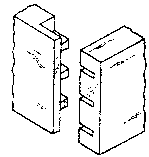
No. 51. The blind miter or secret dovetail is a joint in which only part, say one-half, of both boards is dovetailed, the outer portion being mitered. The edges of the boards are also mitered right thru for a short distance so that when finished the dovetails are invisible. It is used in highly finished boxes.
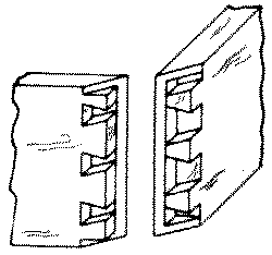
A beveled joint is made by beveling the members so that the plane of the joint bisects the angle at which the members meet. This is called the "miter" and may be 45 degrees or any other angle. It is a neat but weak joint unless reinforced by a spline, nails, or in some other way.
No. 52. A plain miter is a joint where the beveled edges or ends abut and are simply glued or nailed together. It is commonly used in picture-frames, inside trim, columns, boxes, and taborets, four or more sided.
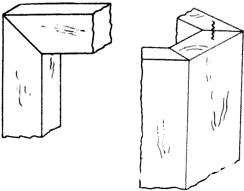
For gluing mitered frames, the most convenient way is with the aid of the picture-frame-vise, Fig. 172, p. 101. Nails are driven or splines inserted as soon as each joint is glued. Where this vise is not available, an ordinary metalworking vise may be used, as follows: Fasten one member, X, face side up, firmly in the vise. Bore holes [page 168] in the other member, Y, at the proper places for the nails. Insert nails in the holes, apply the glue to both mitered surfaces, place the glued surfaces together, letting Y project about ⅛" beyond X. A convenient way to hold Y in place is in the left hand, palm up, while the left forearm rests upon X. Drive one of the nails home, and continue driving until the parts exactly fit. Then drive home the other nail. Now fasten together in the same way the other two members of the picture-frame, and then, one at a time, the third and fourth joint. This is the method used in picture-frame factories, and when once learned is very simple.
For gluing together at once all the members of a mitered frame, the device shown in Fig. 253 is convenient and is easily made. Out of two pieces of wood somewhat longer than the two end [page 169] pieces of the frame, gains are cut of the exact length of the ends, as shown in the illustration. By applying two clamps lengthwise on the frame, all four joints may be glued together at once. If the frame does not come up square, it may be squared by means of a temporary brace, A, in Fig. 253.
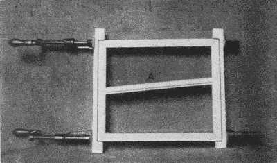
The device shown in Figs. 254 and 255, is also an easily made and efficient tool. At least the small pieces, which receive the corners of the frame, should be made of hard wood such as maple. It is self-adjusting but care must be taken not to buckle the parts of a narrow frame by over pressure. It is well to soap or oil the corner pieces to prevent their being glued to the frame.
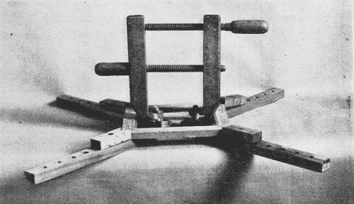
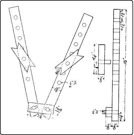
In gluing together long mitered joints, in six or eight sided taborets or columns, in which the members meet edgewise, one method is to wrap a few turns of bale wire around the parts and drive in wedges under the wire to obtain pressure, Fig. 256. Another method is to wrap a stout rope, such as is used for window weights, around all the pieces, properly set up, then to tighten it by twisting it with a stick thru a loop, Fig. 257. A still more effective way is by means of the Noxall Column Clamp, a powerful device, used chiefly for gluing up such pieces as the pillar of a centrally supported table, Fig. 259. Care must be taken with all these devices to protect the corners, unless they are to be rounded off afterward. A good way to protect them is with pieces fastened together in the shape shown in Fig. 258, b, and Fig. 257, the interior angle being equal to the exterior angle of the piece to be glued. In the case of a taboret with slender legs, care must be taken to insert blocks between the separate legs as well, to brace them apart and to keep them from bending under [page 170] the pressure. These methods have the advantage that they are speedy, since all the pieces go together at once; but unless the pieces fit exactly the joints will not close.
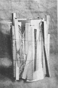
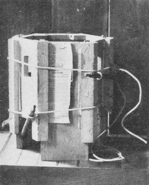
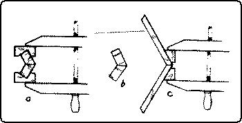
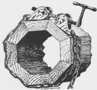
Another method is to glue and clamp the pieces of the taboret together two by two, using blocks as shown in Fig. 258, a. Care should be taken to put the pressure of the handscrews as far out as possible so as to be sure that the outside of the joint closes. This method has the advantage that, as only one joint is glued at a time, the work can be done more deliberately. Moreover, if when three pairs of a six-sided taboret are together, the other three joints do not fit exactly, they can then be refitted.
Another method is to glue pieces of soft wood on the exterior of each pieces as shown in Fig. 258, c. These blocks should be of such shape that the opposite sides of each pair are parallel. When the glue is dry, they are used as corners on which to clamp the handscrews. This method has the disadvantage that the blocks may break loose at a critical moment.
In addition to any of these methods of tightening the joints, to make sure that the ends of the joints close tight, pinch-dogs, Fig. 178, p. 102, may be driven into the end grain, and corrugated fasteners, Fig. 228, p. 125, also driven into the ends, make the joint quite secure.
No. 53. A doweled miter is one in which one or more dowels are inserted and glued into holes bored into the beveled edges. It may be used instead of nails, as in large picture frames.
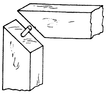
No. 54. A spline or tongue miter is one which has a spline or tongue inserted at right angles to the joint. Since it furnishes more gluing surface, it is stronger than a plain miter.
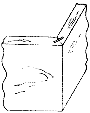
No. 55. A slip-feather or slip-key miter is one which is strengthened by a slip of hardwood glued into a saw kerf cut across the mitered angle. It is used in picture-frames and in boxes.
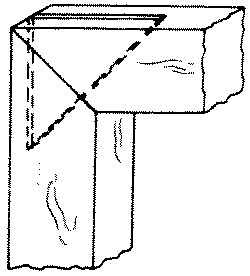
No. 56. A slip-dovetail miter is one in which a trapezoidal shaped key is inserted in a dovetail socket cut straight across the miter. When dressed off, it gives the appearance of a dovetail on each face. It is used for the same purpose as a spline miter.
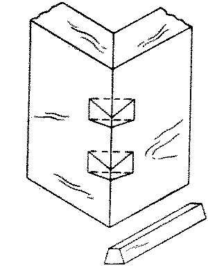
No. 57. A double dovetail keyed miter is one in which a double dovetail key made of hard wood is inlaid across the joint. This is a favorite joint with Oriental joiners.
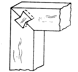
No. 58. A ledge and miter or lipped miter joint is made by rabbeting and mitering the boards to be joined so that the outer portion of the two boards meet in a miter. It is strong and good looking and may be glued or nailed. It is used for fine boxes.
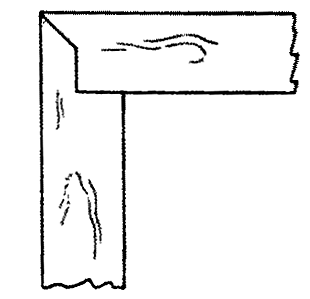
No. 59. A stopped miter is useful for joining pieces of different widths, when both sides can be seen.
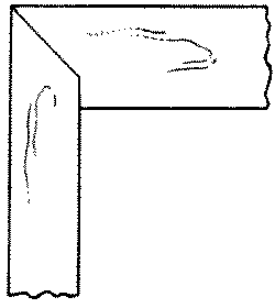
No. 60. A double-tongue miter is made by cutting on the adjoining edges tongues which engage in each other. It is used in high class joinery, on members that join lengthwise of the grain.
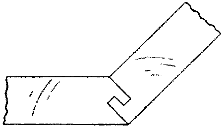
No. 61. A stretcher joint is a slip joint in which one or both sides is mitered. It is used in frames for stretching canvass for paintings by driving wedges from the inside. Two forms are shown in 61a and 61b.
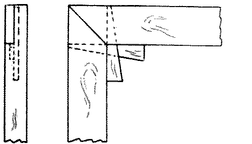
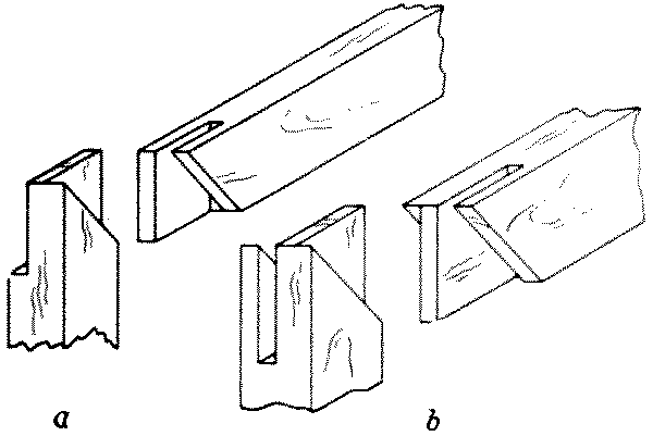
No. 62. A strut joint is a form of miter joint used in making trusses.
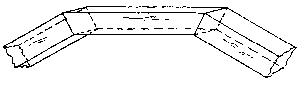
No. 63 and 64. A thrust joint or tie joint or toe joint is one in which two beams meet at an oblique angle, one receiving the thrust of the other. The toe may be either square as in 63, or oblique as in 64. The pieces are bolted or strapped together with iron. It is used for the batter braces of bridges.
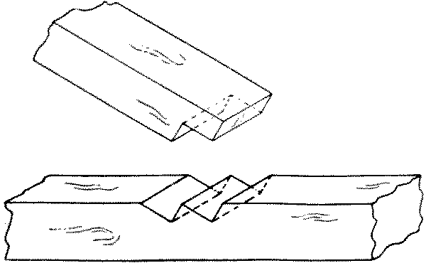
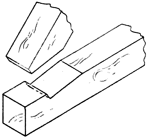
No. 65. A plain brace joint is one in which the brace is simply mitered and nailed into place. It is used for bracket supports.
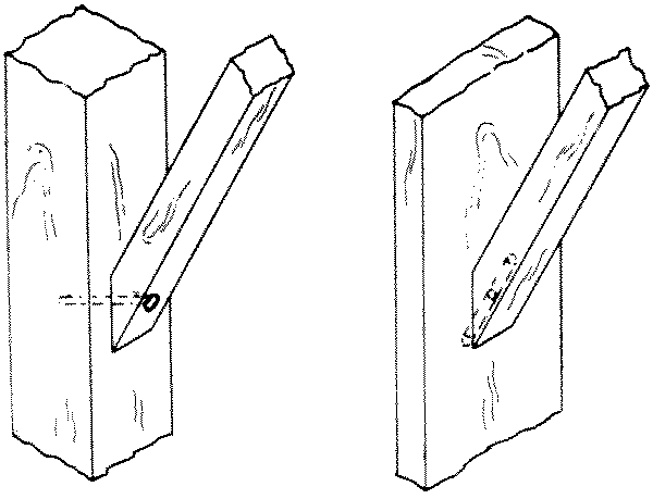
No. 66. A housed brace joint is a joint in which the brace is housed into the rectangular members except that the outer end of the mortise is cut at right angles and the inner end diagonally to receive the brace which is cut to correspond. It is much stronger than 65.
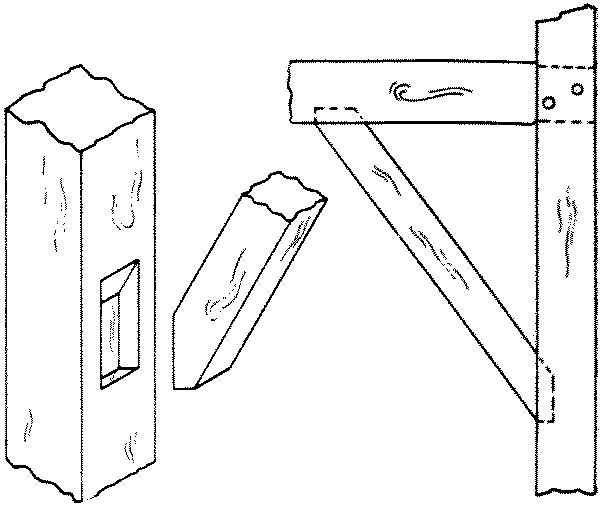
No. 67. An oblique mortise-and-tenon or bevel-shoulder joint is one in which the shoulders of the tenoned beam are cut obliquely and its end is cut off at right angles. The cheeks of the mortise are correspondingly sunk. By these means the tenon prevents lateral motion while the whole width of the beam presses against the abutment. Thus a much larger bearing surface is obtained. The whole is bolted or strapped together. It is used in heavy truss work.
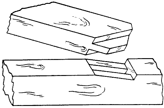
No. 68. A bridle joint is an oblique joint in which a bridle or "tongue" is left in an oblique notch cut out of one beam. Over this tongue is fitted a grooved socket cut obliquely in the other beam. It is used in truss construction.
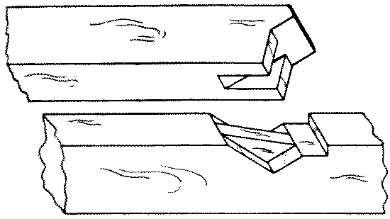
No. 69. A bird's mouth joint is an angular notch cut in a timber to allow it to fit snugly over the member on which it rests. It is used in rafters where they fit over the plate.
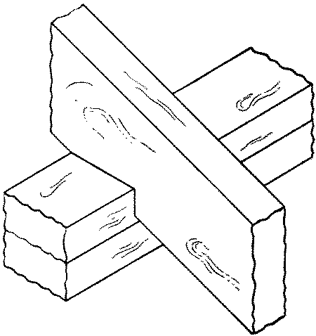
No. 70. A plain or rubbed or squeezed or glue joint is one in which the edges of two boards are glued and rubbed together tight. It is used in table-tops, drawing-boards, etc.
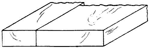
To make this joint, first the boards are all laid down flat, side by side, and arranged in the proper order. Three considerations determine what this order is to be: (1), if the grain is of prime importance, as in quartered oak, then the boards are arranged so as to give the best appearance of the grain. (2), if possible, the boards should be so arranged that the warping of each board shall counteract that of the adjacent ones. For this purpose the boards are so laid that the annual rings of one shall alternate in direction with the annual rings of the next, Fig. 280, a, p. 186. (3), if possible, the boards should be so arranged that after being glued together they can all be planed smooth in the same direction. When the above requirements have been met so far as possible, this order should be marked on adjoining edges for later identification. The edges of the boards to be joined should be finished with a jointer.
There are two principal methods of gluing edge-to-edge joints, rubbing and squeezing. In a rubbed joint, the surfaces to be joined should be planed so as to meet thruout exactly. After properly planing [page 173] one edge of each board, keep one board in the vise, jointed edge up, and place its to-be neighbor in position upon it. Then use these four tests for an exact fit. (1) Sight down the end to see that the faces lie in the same plane. (2) Examine the crack from both sides. Be sure that both ends touch. Test this by pulling down hard on one end of the upper board and noticing if the other end is still in contact. If the other end opens, swing the upper board horizontally on the lower board to see where the high place is and then correct it. (3) See if the upper board stands firmly on the lower board by feeling gently to see if it rocks, or by rapping lightly the lower board. (4) Slide the top board slowly on the lower one to see if it adheres or "sucks."
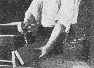
After the pieces have been warmed, which should be done if possible, the glue is spread on them, Fig. 260, and they are then rubbed slowly back and forth in the direction of the grain, pressure being applied by the hand and care being taken not to open the joint in the least. As the glue sets, the rubbing becomes more difficult. It should be stopped when the boards are in their proper relative positions. In rubbing together the edges of two boards, handscrews may be fastened to one in such a way that their jaws serve as guides for the other board to slide between, Fig. 261. Care must be taken to make the jaws of the handscrew diverge enough not to pinch the upper board.
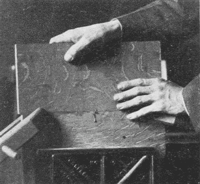
Another method is to clamp a spare board alongside and projecting above the lower board. This spare board acts as a guide against [page 174] which the upper board can be pushed as it is rubbed back and forth. The rubbed joint is especially suitable for short boards.
In joining long boards, a squeezed joint is common. In this case, the edges are planed so as to be very slightly concave from end to end. The object of this is to counteract the subsequent shrinkage which is likely to take place at the ends of the boards before it does at the middle. The pressure of the clamps may be depended upon to close up the middle, and, especially if dowels are inserted, as in No. 75, the joint will be strong enough to resist the elasticity of the boards.
When the fit is good, warm the wood if possible, prepare the clamps, put a thin film of glue over both edges which are to be together, apply the clamps rapidly, keeping the faces flush, and set away to dry for at least six hours. Then another piece may be added in the same manner. If the boards are thin and wide, and therefore likely to buckle, they may first be handscrewed to cross-strips to prevent their buckling. The cross-strips are, of course, slightly shorter than the combined width of the boards so that the full pressure of the clamps may come on the glued joint.
No. 71. A rebated, rabbeted or fillistered joint. Rebating is the cutting of a rectangular slip out of the side of a piece of wood. The re-entering angle left upon the wood is called the rebate or rabbet. A rebated joint, then, is one in which corresponding rebates are taken off edges so that the joined boards may overlap. It is used in flooring and siding.
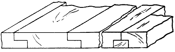
A board is rebated and filleted when two adjoining rebates are filled with a fillet.
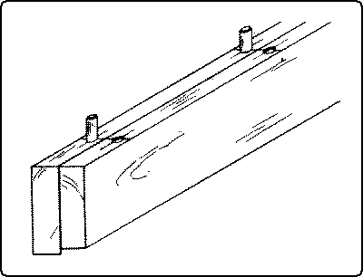
No. 72. A matched or tongue-and-groove joint is made by making a projection or "tongue" in the center of the edge of one board, and a corresponding groove in the center of the other so that they will match together. When used for flooring, the lower side of the grooved board is slightly rebated so that the upper edges will surely touch. This sort of flooring can be blind-nailed.
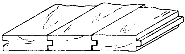
No. 73. A beaded joint is similar to a matched joint except that a bead is worked on one edge to disguise the joint for decorative purposes.
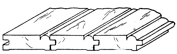
No. 74. A spline-joint is made by plowing corresponding grooves in the edges to be joined and inserting a spline or slip-feather. It is used in plank flooring.
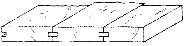
No. 75. A doweled joint is made by jointing the two edges carefully, boring holes opposite each other and inserting dowel pins when the two edges are glued together. It is used in table tops, etc.
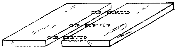
Where the boards are thick enough to allow it, a squeezed joint is greatly strengthened by the insertion of dowels.
The essential point in inserting dowels is to have the holes for them directly opposite one another and at right angles to the surface. The following is a convenient method where boards are to be joined edge to edge, Fig. 262. Place the two boards back to back in the vise with the edges and ends flush. Determine approximately where the dowels are to be inserted. With the gage, mark short lines at the points of insertion in the center of each edge, gaging from the outside faces. Across these lines score accurately with a try-square and knife. Then bore the holes with a dowel-bit at the intersection of the lines, Fig. 263. If this is carefully done, the holes will be directly opposite one another, and equidistant from the faces of both boards. All the holes should be of equal depth, say 1", in order that the dowel-pins, which should also be cut of equal lengths, may be interchangeable. After boring, the holes may be slightly countersunk in order to insure a tight joint and the easy slipping of the pins into place. The latter result may also be obtained by slightly pointing the pins with a dowel-pointer, Fig. 123, p. 83. It is also a wise precaution to cut a small groove along the [page 176] length of the pin to allow superfluous glue to escape from the hole. The dowel should be dipped in glue and inserted when the glue is applied to the joint.
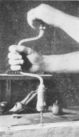
References*
Rivington, Vol. I, pp. 57-77, 135-137, 238-242; Vol.II, pp. 291-295.
Adams, pp. 1-30.
Sickels, pp. 86-124.
Goss, pp. 128-152.
Ellis, pp. 135-151.
Barter, pp. 211-275.
Selden, pp. 56-130.
Building Trades Pocketbook, pp. 217-221, 237.
Griffith, pp. 86-104, 164-170.
* For general bibliography see p. 4.
| Transcriber's Note: The following six pages of diagrams are as they appeared in the original book. They are of poor quality, and the page enlargements are not much improved. These pages have been kept to preserve the original layout, and because they have been linked to from various places in the book. For the convenience of readers, the 75 diagrams have been individually enlarged, repaired where necessary, and inserted after their relevant, numbered, descriptions in the text (above), with links to them from the added lists at the tops of the original pages. |
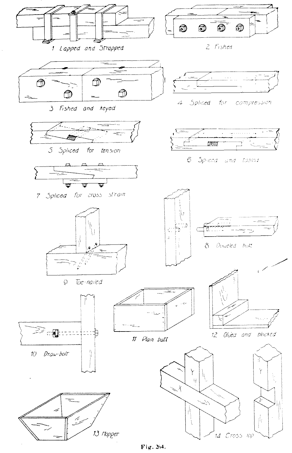
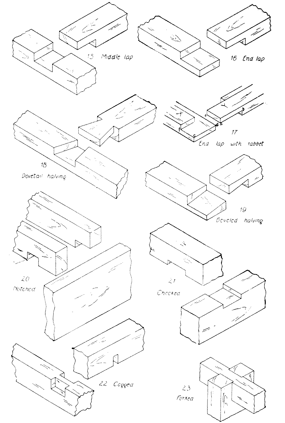
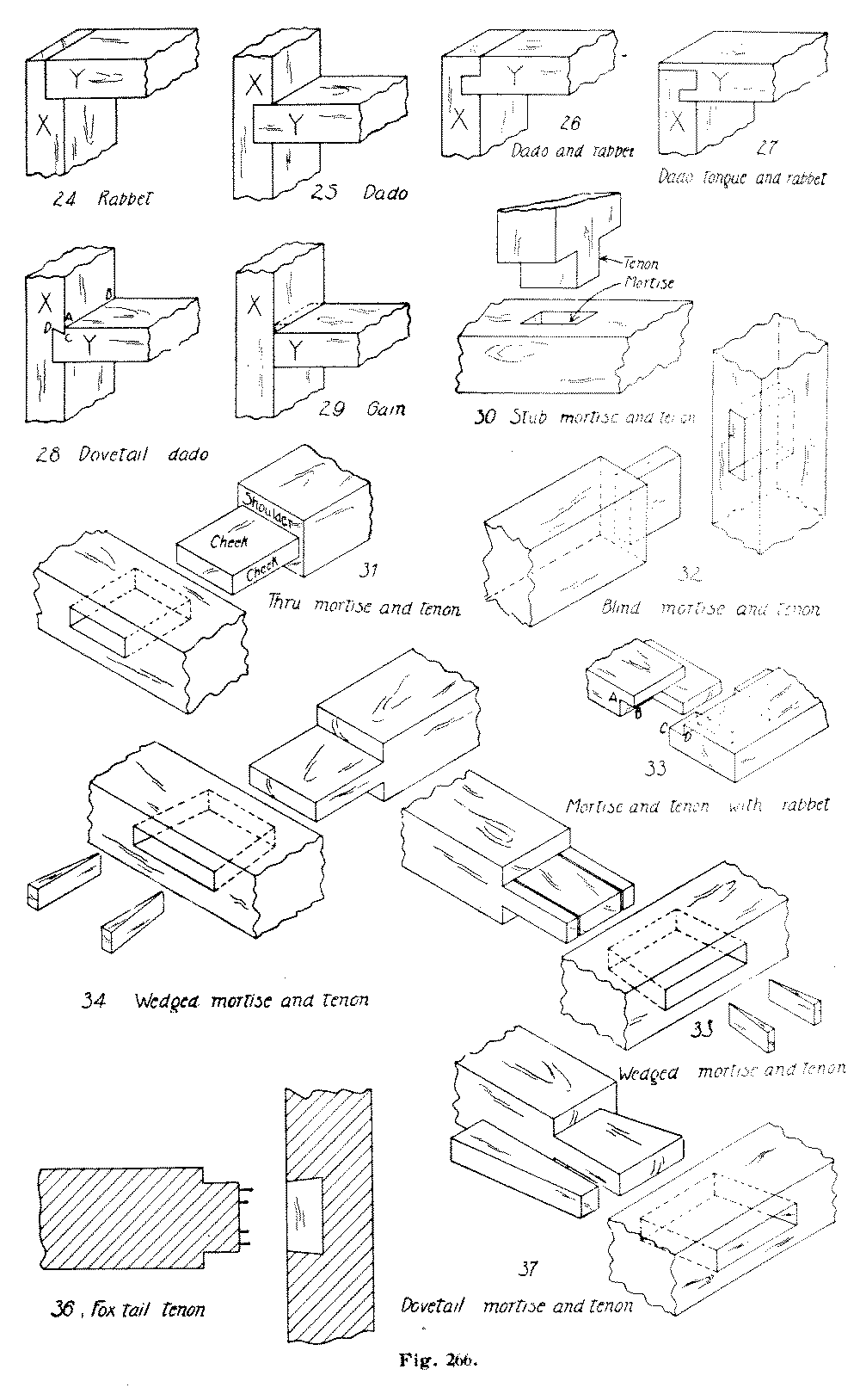
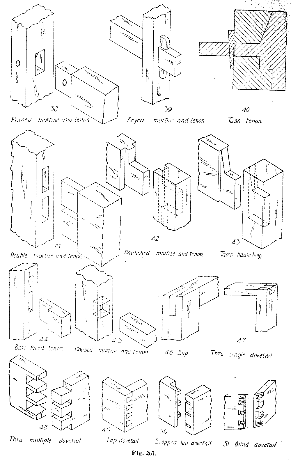
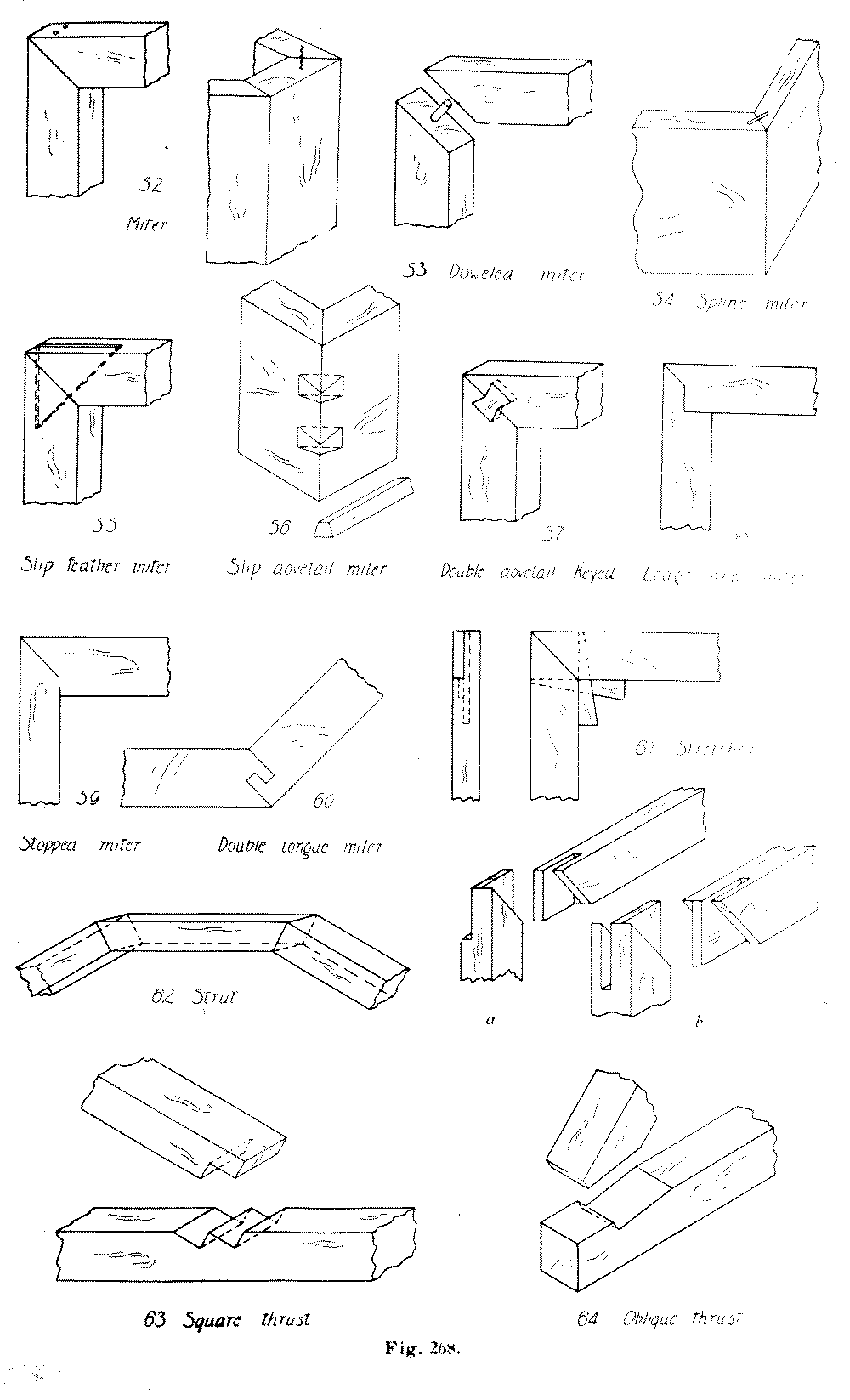
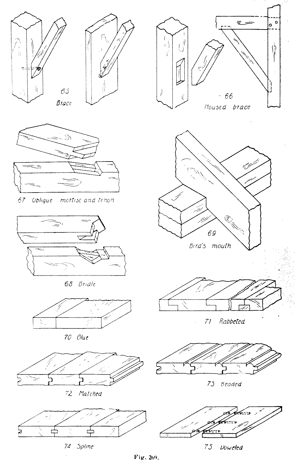
The articles suitable to be made in wood with hand tools may for convenience be divided into four general classes: (1) Unjoined pieces; (2) board structures; (3) panel structures; (4) framed structures. A few illustrations of each class are given below.
Of these there are a number that are advantageous for the learning of tool processes; at the same time they give opportunity for expression in design, and when finished are of use.
Examples are: key-boards, chiseling-boards, bread-boards, sleeve-boards, ironing-boards, coat- and skirt-hangers, and gouged trays. Some of these are so simple as to include hardly any process but planing, directions for which are given above, p. 72.
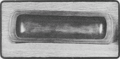
Where there is more than one process involved, the order of procedure is of importance. In general, a safe rule to follow in each case is to plane up the piece true and square, or, in technical language, to "true" it up. At least as many of its surfaces should be trued as are necessary for the "lay out." Where the piece is to be rectangular all the surfaces should be true; where some of the surfaces are to be curved it is unnecessary and a waste of time to square them first. For example, in making a gouged tray with curved outline, Fig. 270, the working face, the working edge, and the thickness should all be true before the plan is laid out. Then, after the outline is drawn, the trough may be gouged, the outline cut with turning-saw, chisel, and spokeshave, and the edges molded with the gouge or chisel. If there is incised decoration it should be cut [page 184] before the molding is cut, so that while being incised, the piece will lie flat without tipping.
These simple pieces, as well as others, are often embellished by chamfering. A chamfer is a surface produced by cutting away an arris. It differs from a bevel in that a bevel inclines all the way to the next arris, while a chamfer makes a new arris, Fig. 271. A thru chamfer extends the whole length or width of a piece, while a stop chamfer extends only part way. For the laying out of a chamfer see p. 115.
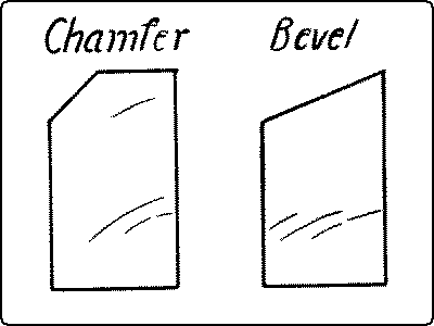
Thru chamfering is best done with a plane, Fig. 272. For this purpose the piece may be held in the bench-vise and the plane tipped to the proper angle, or the piece may be held in a handscrew which in turn is held in the vise as in Fig. 175, p. 101. The chamfers with the grain should be planed before those across the grain.
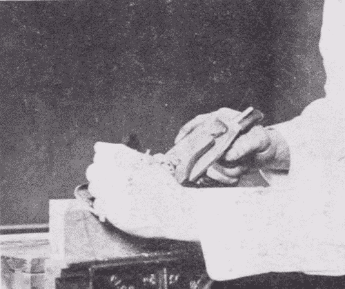
In chamfering a four-square stick into an eight-square, the piece may be gripped in the vise diagonally, Fig. 273, or it may be held in a trough made of two strips of wood from each of which an arris has been chamfered and then the two nailed together, Fig. 274. A dowel or nail may be inserted in the trough for a stop. Stop chamfers are pared best with a chisel, Fig. 275, held according to convenience either flat side or bevel side up. See under chisel, p. 53.
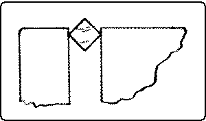
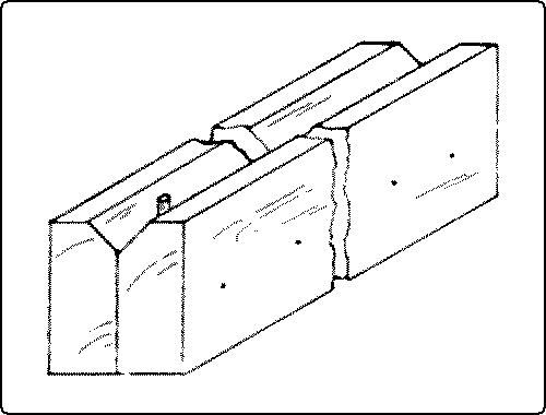
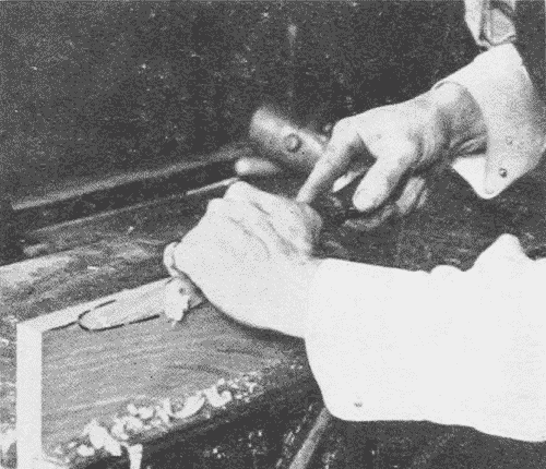
These include such pieces as wall brackets, sets of shelves, book-racks, plate-racks, drawing-boards, foot-stools, taborets, and boxes.
The advantage of this form of construction is that it is comparatively easy to make; the disadvantage is that if the boards are wide, they are sure to shrink and swell. It is wise in all such work to true and smooth up all the pieces at once, and if the wood is not thoroly [page 185] seasoned, to keep the boards under pressure till they are assembled. In the case of several boards to be jointed into one piece, they should be glued together before the surfaces are smoothed. Suggestions regarding a few typical pieces follow:
Wall Brackets. (1) There are three essential parts, the shelf, the support or supports, and the back: the shelf to hold the articles, the support to hold up the shelf, and the back to hold all together, Fig. 276, a. The grain of the wood in the shelf should run left and right, not forward and back, because thus it rests on the support in such a way as not to break easily, and it also acts as a stiffener for the back. In case the back extends above the shelf, as in Fig. 276, a, the shelf can be secured firmly to the back, since there is side grain in which to drive nails or screws. As to the direction of the grain of the support and the back, this should run in the direction of the largest dimension of each. Where the back is long horizontally, for security in hanging, it is better to have two supports.10
Footnote 10: See the School Arts Book for Nov., 1906, "Design in the Woodworking Class," by Anna and William Noyes.
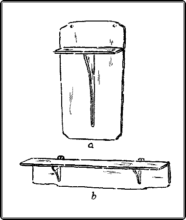
Wall book-shelves, Fig. 277, plate-racks, etc., are simply compound brackets. The shelf is the essential piece, the sides take the place of the supports, and the back is often reduced to strips merely wide enough to give rigidity.
The shelves may be either gained into the supports, Fig. 266, No. 28 or No. 29, p. 179, or a keyed mortise-and-tenon may be used, Fig. 277. In the latter case the back strip may have a short barefaced blind tenon which is mortised into [page 186] the upright, Fig. 278. It also fits into a rabbet on the upper back side of the shelf. Made in this way the shelves can be knocked down easily.
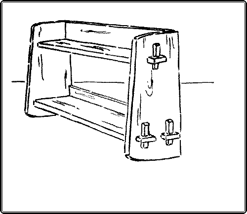
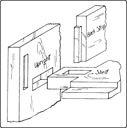
Foot Stool or Cricket, Fig. 279. The grain of the supports should run up and down, because pieces with the grain horizontal would be likely to break under pressure. Braces or a rail give additional support. The top should not be larger than the base of the legs; otherwise a person standing carelessly on the stool is in danger of being upset.
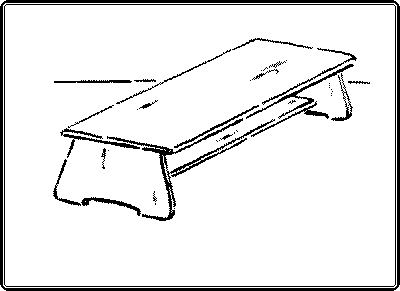
A Drawing-Board is made up of narrow boards, with glued joints, with the boards so laid that the annual rings will alternate in direction, Fig. 280, a. It must be made so that it can shrink and swell and yet remain flat. For the purpose of giving lateral stiffness cleats are added. They may simply be screwed on the underside, the screw holes being large enough to allow for shrinkage, or they may be dadoed in with a dovetail dado, Fig. 280, b, or they may be grooved to admit a tongue on the end of a board, Fig. 280, c. In this case screws passing thru large holes in the cleats hold them in place.
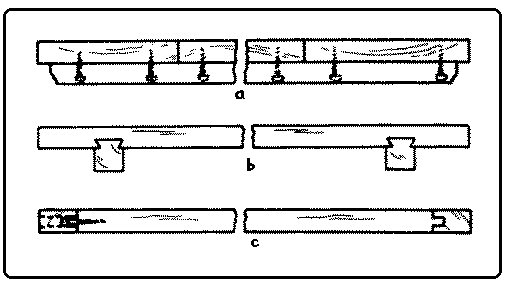
Taborets. The term taboret originally meant a little tabor or drum, and was therefore used to designate a small stool, the seat of which consisted of a piece of stretched leather. The term now includes small, tablelike structures for holding flowerpots, vases, etc. It might more properly be called a "table-ette."
[page 187]When made up with boards having their long edges mitered, it has from four to eight sides. A six-sided one is shown in Fig. 281. In making, it is best to fit the joints exactly first, while the board is stiff, and then to cut out the pattern of the legs. Directions for gluing are given on p. 169.
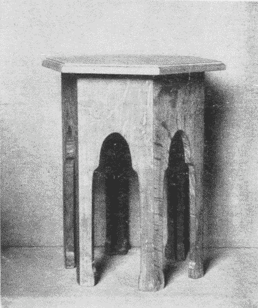
Scrap-boxes, Fig. 282, and flower-pot boxes may be made with the same construction.
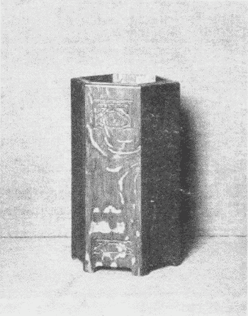
Rectangular Boxes. There are various methods of joining their sides. The butt joint, Fig. 264, No. 11, p. 177, is plain, simple, and good for coarse work. This joint may be reinforced as in packing boxes, Fig. 283.
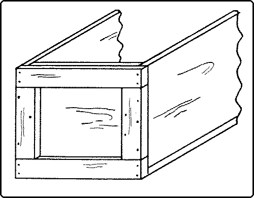
Mitered joints, Fig. 268, No. 52, p. 181, are neat but weak, unless reinforced by a spline, Fig. 268, No. 54.
The rabbet or ledge joint, Fig. 266, No. 24, p. 179, is both strong and neat. It can be glued and also nailed if desired.
The rabbet and dado joint, Fig. 266, No. 26, can be glued without nails and is good for small boxes.
The housed dado, Fig. 266, No. 25, is good for water-tight boxes.
The mitered ledge, Fig. 268, No. 58, makes a very neat, strong joint which can be nailed or glued, but is more difficult to fit than a simpler joint.
The dovetail joint, Fig. 267, No. 48, is very strong and honest, but the joint is prominent from the outside and it takes much time and labor to make. It is glued.
The blind dovetail, Fig. 267, No. 51, is very neat and strong, and the [page 188] joint is entirely concealed when done, but is very difficult to make.
The Bottoms of Boxes. The plain or full bottom, Fig. 284, A, is likely to shrink (see dotted line), and it is held in place only by the friction of the nails. The extended bottom, Fig. 284, B, overcomes the objection to shrinkage and adds a decorative feature. The bottom may be set in, Fig. 284, C. This is stronger than the plain bottom, but the nail holes show. The bottom may be rabbeted in, Fig. 284, D. This is better than the set-in bottom so far as the showing of the nail holes goes, for the nails may be driven in from below, and a little shrinkage is not conspicuous. It is practicable, if a rabbet or mitered joint is used in the sides, but if the side pieces are butted or dadoed, the rabbet for the bottom shows. This may be cleverly concealed by an insert, but that is patchwork, and not first-rate construction.
Reinforced bottom, Fig. 284, E. A plain or full bottom is sometimes covered by a base or cover strip to hide the joint and secure the bottom, as in tool chests. This strip may be mitered at the corners.
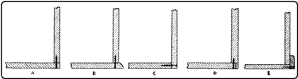
The Lids of Boxes. The simplest form is a full flat cover, Fig. 285, A, which may be nailed or screwed to the box, as in packing cases. The cover may slide into a groove, Fig. 285, B, along the sides and into one end, the other end being lowered to admit it. The cover may have cleats on its underside, Fig. 285, C, which fit just inside the box and keep the top in place. The cleats also prevent the [page 189] top from warping. This is a common Japanese construction, even in fine boxes. The Japanese tie the top on with a tape or ribbon.
The lid may be boxed, Fig. 285, D, that is, portions of the sides may be affixed to the top. These extra pieces are a help to stiffen the top and to keep it from warping. A boxed top may have the top board flush with the sides, Fig. 285, E. The disadvantage of this is that the top may shrink and part from the sides and give a bad appearance. The overlapping top, Fig. 285, F, obviates this trouble of shrinkage and adds a decorative element. In this case the top may be glued on or screwed from below thru the side strips.
The top may be mitered into the sides, Fig. 285, G. The shrinkage trouble still obtains here. Otherwise the appearance is excellent. The top may be paneled into the sides, Fig. 285, H. This has a good appearance if the sides are mitered and ledged but not if the sides are butted or dadoed, because then the groove for the top shows.
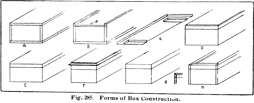
Any of these lids may be made removable or hinged, except the sliding top. For methods of hinging see p. 132.
In gluing boxes together, it is a good plan to glue the ends and sides together first and to let these joints dry before gluing on the bottom and, in the case of a boxed top, Fig. 285, D, the top. Care must be taken to see that the sides do not bow under the pressure. To prevent this, one or more false, temporary partitions as A, B, in Fig. 286, of exactly the length to keep the sides straight, may be inserted. In gluing together boxes with rabbeted joints, Fig. 285, H, pressure should be applied in both directions. [page 190] In gluing on the bottom of a box that is also to be nailed, the nails should be driven into the bottom first, so that the points just come thru. These points sticking into the sides will prevent the bottom from slipping when pressure is applied. It is often undesirable to have nail heads show, as in a top. In such a case, and also to prevent the top from slipping under pressure, a couple of small brads may be driven part way into the upper edges of the sides, the heads bitten off with the nippers, and points filed on the projecting portion.
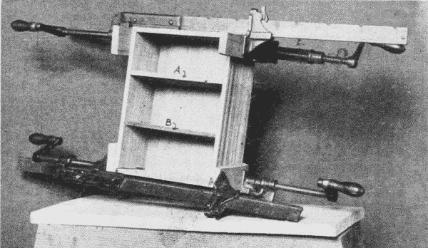
Drawers. In the best form, the sides are dovetailed to the front for strength, Fig. 287, for whenever the drawer is opened the front tends to pull away from the sides. This dovetail is half blind, so that the joint will not appear when the drawer is shut. In order that the drawer may always run freely and yet the front fit the opening as close as possible, it is common practice to cut a shallow rabbet on the ends of the front, so that the body of the drawer is a little narrower than the front is long, Fig. 287. Or the front may be attached [page 191] to the sides with a dado tongue and rabbet joint, Fig. 266, No. 27, p. 179.
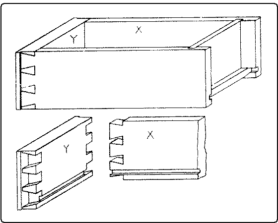
The bottom is grooved into the sides with its grain parallel to the front and fastened only to the front so that it has plenty of play for shrinkage. The back is dadoed into the sides, with either a straight dado, Fig. 266, No. 25, p. 179, or dovetail dado, Fig. 266, No. 28, and rests on the bottom. The extension of the bottom beyond the back allows ample room for shrinkage.
The best machine-made drawers are now made with the bottom paneled or dadoed in all around so that papers cannot slip out. The back, as well as the front, is dovetailed.
Directions for Making a Table Drawer. Dress the front and sides to size. Fit the front of the drawer to its place in the table or cabinet, leaving a little play all around it. Plow the groove in the front and sides for the drawer bottom. For ordinary drawers, a groove ¼" wide is proper. If the ends of the front are to be rabbeted (see above), do this next. The sides are best joined to the front with the half-blind dovetail joint. (For directions see p. 166). After fitting these, lay out and cut the dadoes for the back of the drawer. Prepare the bottom of the drawer thus: the [page 192] grain should run right and left, never front and back. If the drawer is so long as to require it, glue-joint the bottom, and fit it snugly to place. There need be no play right and left, and the bottom should extend as far back as the sides. If necessary, bevel the under side to fit the grooves. Assemble all the parts to see that they fit, take them apart, glue the sides to the front and back, slip the bottom into place, apply the clamps, and see to it that all joints are square, using a diagonal brace if necessary, Fig. 294. Fasten the bottom to the front by means of a thin block glued into the interior angle between the under side of the bottom and the back side of the front. When dry, clean up the drawer and fit it to its place.
These include doors and cabinets of all sorts. The principle of panel or cabinet construction is that there shall be a frame composed of narrow members whose grain follows the principal dimensions. In the best construction this frame is mortised and tenoned together and within this frame there is set a thin board or panel which is free to shrink or swell but is prevented from warping by the stiffer frame. The object is to cover an extended surface in such a way that the general dimensions and good appearance will not be affected by whatever shrinkage there is. Since the frame itself is made up of narrow pieces, there is but little shrinkage in them. That shrinkage is all that affects the size of the whole structure, because wood does not shrink longitudinally to any appreciable extent. The shrinking or swelling of the panel does not affect the general size. The cross construction of the frame also prevents [page 193] warping, since, in the best construction every joint is mortised and tenoned. The panel may simply be fastened on the back of the frame, but a better construction is to insert it in a groove made in the inside of the frame in which the panel is to lie and have free play. The panel may be made of one board or of matched boards, may be plain or have raised or carved surfaces, or be of glass; and the joints between frame and panel may be embellished with moldings mitered in, but the principle is the same in all cases.
The frame of a door, Fig. 288, illustrates the panel construction. The upright, outside pieces are called the "stiles," the horizontal pieces the "rails." There are also the "top-rail," the "bottom-rail," the "lock-rail" (where the door-knob and lock are inserted), and sometimes the "frieze-rail" between the lock rail and the top rail. The "muntin" is the upright between the two stiles.
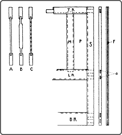
The joint commonly used is the haunched or relished mortise-and-tenon, Fig. 267, No. 42, p. 180; (See p. 163 for directions for making). The tenon is sometimes doubled, Fig. 288, and a fillet (f) may be inserted to cover the ends of the tenons, or the joint may be a blind mortise-and-tenon, Fig. 266, No. 32, or in cheap construction, dowels may be used. The best doors are now made with cores of pine covered on the visible sides with heavy veneer. Large surfaces are covered by increasing the [page 194] number of parts rather than their size, as in wainscoting.
Picture-frames also belong in this class of structures, the glass taking the place of the panel. They are made with mortise-and-tenon joints, Fig. 266, No. 33, slip joints, Fig. 267, No. 46, dowelled butt joints, Fig. 264, No. 8, end lap joints, Fig. 265, No. 17, and, far more commonly, mitered joints, Fig. 268, No. 52. Mitered joints are the easiest to make, for the joints can be cut in a miter-box, Fig. 181, p. 103, and glued in a picture-frame-vise, Fig. 172, p. 101. This joint needs reinforcement by nails, Fig. 268, No. 52, by dowels, No. 53, or by splines, No. 55. If the sides are of different widths, the fitting of the joint is more difficult. Mitered joints are the only kind suitable for molded frames. The rabbets are cut out with a rabbeting-plane before mitering and assembling.
The principle disadvantage of a mitered joint is that, if the wood shrinks at all, it opens at the inside corners, as in Fig. 289, because wood shrinks sidewise but not lengthwise.
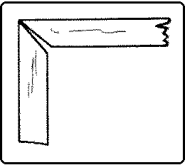
In window sashes, the dovetail joint, Fig. 267, No. 47, is the common one at the upper end of the lower sash and the lower end of the upper sash, and the mortise-and-tenon joint modified is used at the lower end of the lower and upper end of the upper sash. The glass takes the place of the panel. In blind sashes, the pinned mortise-and-tenon joint, Fig. 267, No. 38, is commonly used.
[page 195]When panels are joined together to enclose a space, then we have what is properly called cabinet construction. Illustrations are cabinets, bureaus, desks, lockers, chests, etc.
In all these cases, the constructed panels may be treated as separate boards and joined together with dowel pins or splines or dadoed together without any other framework, tho the corners are often reinforced by cleats or blocks glued into them. Sometimes, however, as in chests, Fig. 290, posts are used instead of stiles, and rails are mortised or doweled into them and the panels set into grooves in both posts and rails. In this case the bottom is raised from the floor, and may be dadoed into the bottom rails, or dowelled into them or even supported by strips attached along their lower inside edges. The chest really is a union of both paneled and framed structures.
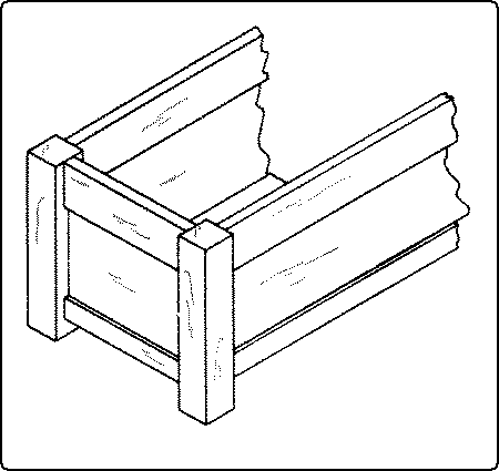
The principle of the framed structure is similar to that of the panel construction in that the object is to allow for shrinkage without harm to construction and also to economize materials. Common examples are tables, chairs, work-benches, and frame houses.
The Making of a Table. The standard height of a table is 30". There should be 25" clearance under the rails. This leaves approximately 4" for the width of the rails. Assuming that the table is to be of a simple straight line type with one drawer, the following method of procedure is suggested:
Cut the boards for the top to the approximate length and stick, (see p. 48) and clamp them, so as to season them as well as possible before jointing.
Dress to size the legs and rails. Stand the legs in their proper positions relative to each other, and mark them F R (front right), F L (front left), B R (back right), and B L (back left). Plow out the grooves on the inside of the rails for the fastenings of the top, Fig. 297, D, if they are to be used. Lay out and cut the tenons and mortises for the end rails and back rail.
The proper form of the tenon is one with a wide shoulder above it so that the top of the leg above the mortise will not shear out. The [page 196] rails should be set near the outside of the leg so that the tenon may be as long as possible and the portion of the leg inside it as strong as possible. A haunched mortise-and-tenon joint, Fig. 267, No. 43 is sometimes used, giving additional lateral stiffness to the rail. The proper proportions are shown in Fig. 291. When cut, these parts should be temporarily assembled to see if they fit.
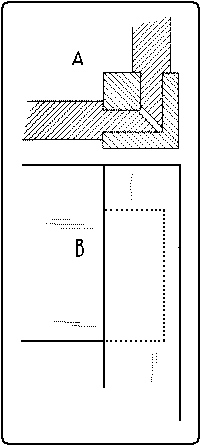
Inasmuch as a drawer takes the place of a front rail, the front legs must be tied together in some other way. For this purpose two stringers or drawer rails may be used, their front edges being as far from the face of the legs as are the rails from the side and back. The upper drawer rail may be dovetailed at both ends into the tops of the legs, as shown in Fig. 292. If this takes more room than can well be spared from the depth of the drawer, it may be omitted, but it adds greatly to the stiffness of the table and is an excellent means of fastening on the top by the use of screws passing thru it.
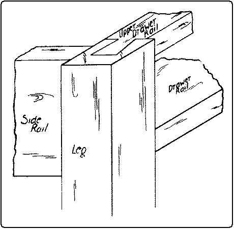
The drawer rail, also called the fore edge, is long enough to partly overlap the side rails, into the lower edges of which it is gained so as to be flush with them, and may be fastened to them with screws, Fig. 293. The construction may be further strengthened by also doweling the end of this stretcher into the legs. If there are two drawers, the partition between them may be doweled or gained into these upper and lower stretchers.
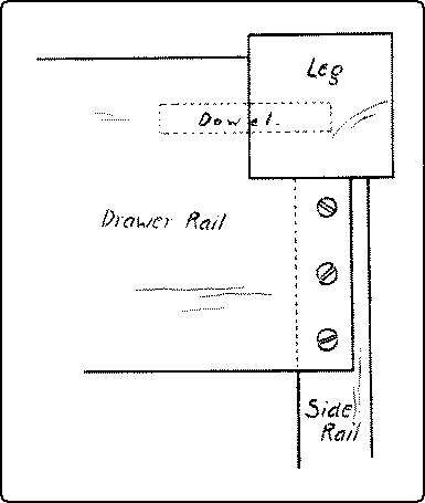
If the legs are to be tapered or otherwise shaped, that should be done next. Then glue and assemble the end rails with their proper legs, taking care to see not only that the joints come up square, but that the legs are in the same plane. Finally assemble the whole, inserting, if necessary, a temporary diagonal brace to insure squareness, Fig. 294. When dry, clean up the joints. For the making of a table drawer, see above, p. 191.
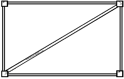
To fit the drawer to its place, runners and guides, Fig. 295, must first be fastened in. The runners are in line with the drawer rail, and are glued and nailed or screwed to the side rails between the back of the lower stringer and the back posts. On top of them and [page 197] in line with the inner face of the legs are the guides running between the front and back posts. Or the runner and guide may be made of one piece properly rabbeted out.
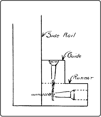
If there are two drawers, a double runner lies between, and is gained into the middles of the back rail and the stringer, and on it is a guide for both drawers, equal in width to the partition between the drawers. The drawers should run easily in their proper places. In order to insure this, the drawer should be slightly narrower than the opening which receives it. A little French chalk, rubbed on the sides and runners, makes the running smoother. Sometimes the opening for a drawer is cut out of the front rail, as in Fig. 296. In this case the drawer runners are supported between the front and back rails, into which they may be gained.
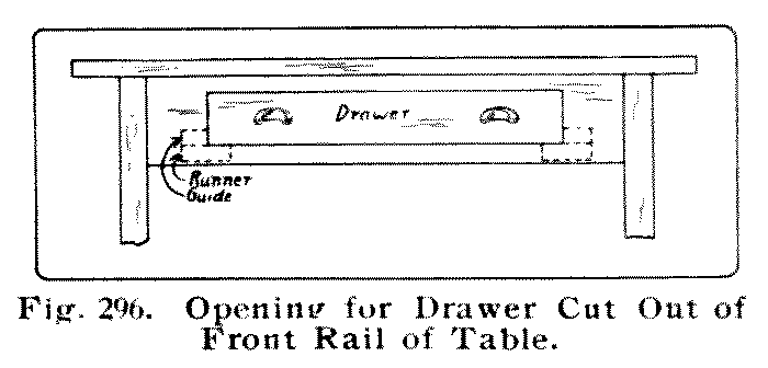
For the making of the table top see edge-to-edge joint, p. 172. Dress up the top to size, taking special pains with the upper surface. If the grain is crossed, use the veneer-scraper, Fig. 151, p. 92, then sand, first with No. 1, then with No. 00 sandpaper, finish the edges carefully, and attach to the frame.
For fastening the top to the table rails, several methods are used. The top may be screwed to the rails by the screws passing thru the rails themselves either straight up, Fig. 297, A, or diagonally from the inside, B, or thru blocks or angle irons, C, which are screwed to the inside of the rails, or thru buttons, or panel irons, D, which are free to move in a groove cut near the top of the rail. The last [page 198] method is the best because it allows for the inevitable shrinkage and swelling of the top.
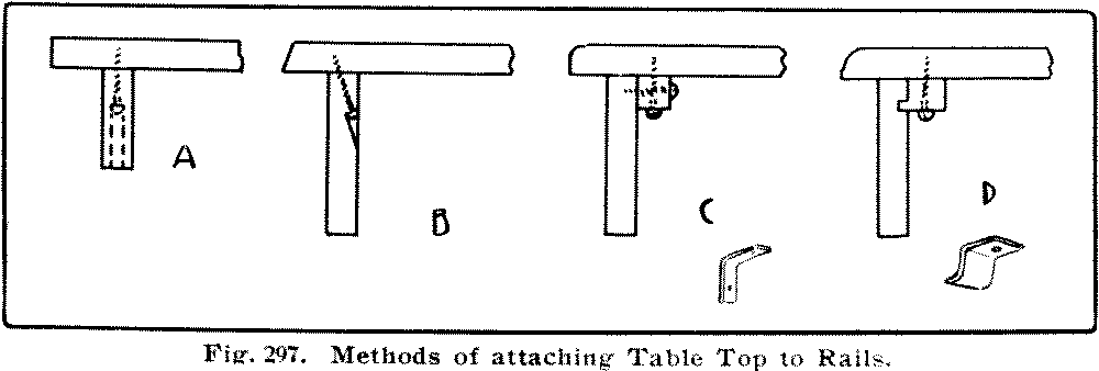
Chairs may be so simplified in form as to be possible for the amateur to construct. The two front legs and the rail and stretcher between them offer little difficulty because the angles are square.
The two back legs, may, for the purpose of simplification, be kept parallel to each other and at right angles to the seat rails between them, as in Fig. 298, A, and not at an angle as in B. The joining of the back will then offer little difficulty. The principal difficulties lie in the facts that for comfort and appearance the back of the chair should incline backward both above and below the seat, and that the back of the seat should be narrower than the front. By keeping at right angles to the floor the part of the back legs which receives the seat rail, the side seat rails will meet the back legs at a right angle in a side view, Fig. 298. The back legs should be slightly shorter than the front legs, as shown in D.
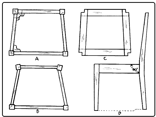
The second difficulty involves the making of inclined mortise-and-tenon joints, A, where the side rails fit into the legs. The making [page 199] of these can be facilitated by laying out a plan of the full size and taking the desired angles directly from that. It is common to reinforce these joints with corner blocks glued and screwed in place as shown in A. If there are additional rails below the seat rails, the easiest way to fit them in place is first to fit and clamp together the chair with the seat rails only, taking pains to have all angles perfectly true, and then to take the exact measurements for the lower rails directly from the chair. The same method may be used for laying out a stringer between the lower rails.
If it is desired to bow the rails of the back, which are above the seat rail, this can be done by boiling them in water for 30 minutes and then clamping them over a form of the proper shape, with a piece of stiff sheet iron on the outside, as in Fig. 299. They should be thoroly dried in a warm place. Then the tenons may be laid out on the ends parallel to a straight-edge laid along the concave side. The chair bottom may be made of solid wood, either flat or modeled into a "saddle seat;" it may be covered with cane or rush, or it may be upholstered.
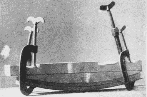
To upholster a chair seat, a frame should first be made of the shape shown in Fig. 298, C. The strips are about 2" wide and ½" thick with their ends half-lapped. The seat rails are rabbeted ½" deep and ½" wide to receive this frame, which should be ⅛" smaller all around than the place to receive it. The returns at the corners fit around the legs at ⅛" distance from them. This ⅛" provides space for the coverings. After the frame is fitted, it is covered [page 200] with 3" webbing tacked firmly to the upper side. The webbing which goes back and forth is interwoven with that which goes from right to left. Over this is stretched and tacked (also to the upper side) a piece of unbleached muslin. A second piece of muslin is tacked to the back edge and part way along the side edges, leaving for the time the corners unfinished. In the pocket thus formed horsehair or other stuffing is pushed, care being taken to distribute it evenly and not too thick. When the pocket is filled, the muslin is tacked farther along the sides and more hair put in, until the front is reached, when the muslin is tacked to the front edge. The corners are now drawn in tight, a careful snip with the scissors parting them diagonally so as to lie in well. The partings may be turned down and tacked on the under side of the frame.
Finally the leather or other covering is stretched over the whole as evenly as possible. The corners should be left to the last, then [page 201] clipped diagonally to the exact inside corner and the partings drawn down and tacked, as was the muslin. The superfluous leather may then be trimmed off, and the seat should fit in its place. Or the seat frame may be omitted, and the coverings tacked directly to the chair rails.
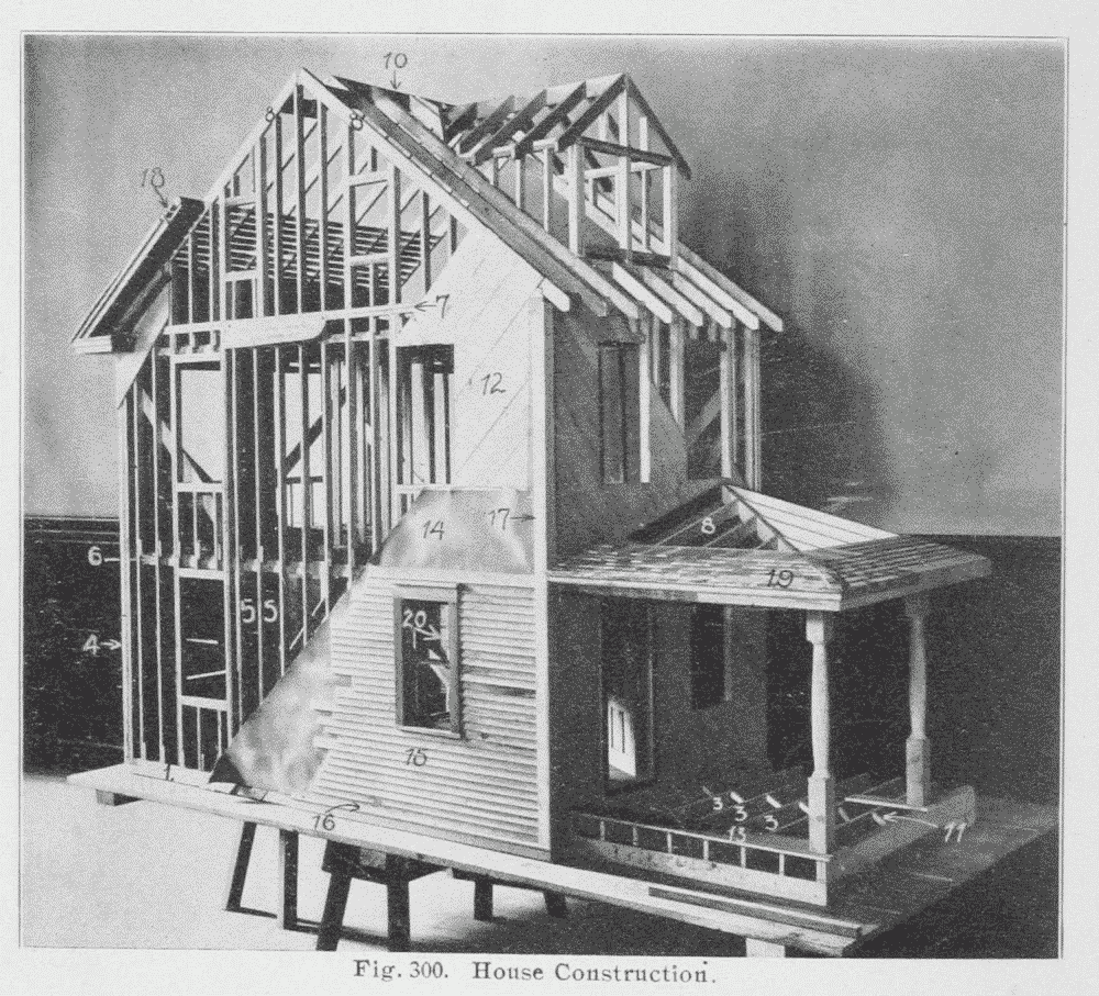
The balloon-frame house is a typical form of framed construction, Fig. 300. The essential parts of a balloon-frame are:
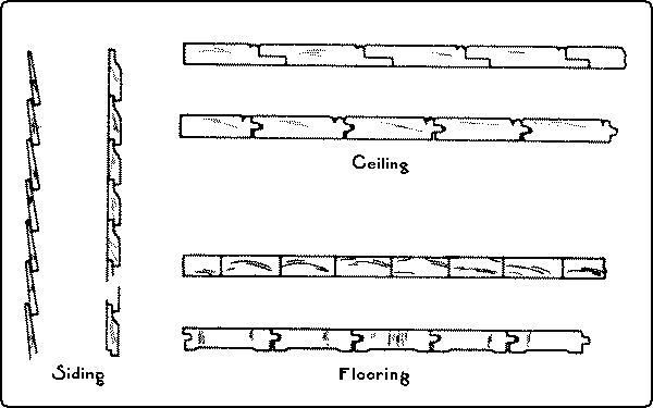
References*
Simple Joined Structures.
Benson, pp. 32-37.
Goss, pp. 91-96.
Noyes, School Arts Book, 6: 89, 179.
Wheeler, pp. 86, 219-227, 376.
Sickels, p. 120.
Griffith, pp. 84-104.
Panel and Cabinet Construction.
Goss, pp. 117-118, 148-151.
Compton, pp. 146-151.
Sickels, p. 134.
Wheeler, pp. 366-372.
Framed Structures.
Crawshaw.
Wheeler, pp. 203-206, 238-297.
Sickels, p. 124.
Building Trades Pocketbook, pp. 221, 230.
Coverings.
Sickels, pp. 128-131.
Goss, pp. 141-144.
* For general bibliography see p. 4.
[page 203]Footnote 11: Professor Rankine's Five Principles:
1. To cut the joints and arrange the fastenings so as to weaken the pieces of timber they connect as little as possible.
2. To place each abutting surface in a joint as nearly as possible perpendicular to the pressure which it has to transmit.
3. To proportion the area of each surface to the pressure which it has to bear so that the timber may be safe against injury under the heaviest load which occurs in practice, and to form and fit every pair of such surfaces accurately in order to distribute the stress uniformly.
4. To proportion the fastenings so that they may be of equal strength with the pieces which they connect.
5. To place the fastenings in each piece of timber so that there shall be sufficient resistance to the giving way of the joint by the fastenings shearing or crushing their way thru the timber.
1. Avoid multiplication of errors by making all measurements (as far as possible) from a common starting point, and laying off all angles from the same line or surface. Illustrations of this principle are as follows: Before proceeding with other processes, a working face and working edge and as many other surfaces as will finally appear in the finished piece, should be trued up. At least the working face and working edge are essential to the proper "lay-out" of the piece, whenever measurements are made from an edge.
In laying out a series of measurements, it is important, when possible, that the rule be laid down once for all, and the additions be made on that, rather than that the rule should be moved along for each new member of the series.
In scoring around a board with knife and try-square, the head of the try-square should be held against the working face in scoring both edges, and against the working edge in scoring both faces, and not passed from one surface to another in succession.
In the laying out of a halved joint, Fig. 265, Nos. 15-19, p. 178, the gaging is all done from what will be one of the flush surfaces of [page 204] the joined pieces. Then, if the gaged line should be slightly more or less than half the thickness of the pieces the closeness of the joint would not be affected.
2. When possible, in laying out a joint, use the method of superposition. Fig. 302. By this is meant the method by which the lay-out of one member is obtained directly from the other by laying (superposing) the latter on the former and marking or scribing the needed dimensions directly, instead of by measurement. It has the advantages of simplicity, speed, and greater probability of fit.
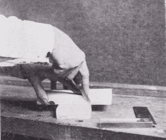
Familiar illustrations are in the making of halved joints, Fig. 265, Nos. 15-19, p. 178, dovetail joints, Fig. 267, Nos. 42-45. p. 180, and scarfed or spliced joints, Fig. 264, Nos. 4-7. p. 177.
3. Work systematically. In case the same process is to be repeated on a number of parts, complete this process in all before taking up another process. This is the principle of the division of labor applied to the individual workman.
In laying out duplicate or multiple parts, the proper cross measurements should be carefully laid out on one piece and then transferred with a try-square to the other parts laid accurately beside it. So when a number of like pieces are to be gaged, all the parts requiring the same setting should be gaged before the gage is reset for another gaging. This is a great saving of time and insures accuracy.
In making a number of like parts, if they are not too large much of the work can often be done in one piece before it is cut up. For example, to make a number of slats from a given piece of wood, the piece may first be brought to such dimensions that the length will be correct for the finished pieces and the thickness of the piece be equal to the width of the slats, Fig. 303. The face may then be gaged with a series of lines so that every other space will be equal to the required thickness of each slat, and the alternate spaces be just sufficient for [page 205] the saw kerf and dressing. The slats may then be ripped apart and dressed to size.
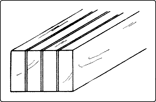
Or a long strip may be planed to thickness and width and then be sawn up and finished to the proper lengths. For example, in a mitered picture-frame it may be convenient to plane up two pieces, each one long enough to make one long side and one short side.
In fitting up framed structures each part when fitted should be distinctly marked, so that there may be no confusion in assembling.
4. Where practicable secure the same conditions of grain in different elements of joined structures.
Illustrations of this are as follows: The grain of the sides of a box should run continuously around the box, or, in the case of a tall, slim box, the grain of all the sides should run up and down. In either case, the grain in the different sides is parallel. In a rubbed joint, Fig. 269, No. 70, p. 182, to be planed down afterward, in case the grain is not straight, much trouble in planing may be saved if the different pieces are laid so that they can all be planed smooth in the same direction. This may not be possible where the boards are joined so as to match the grain, as in quartered oak, or where the annual rings of slash boards are made to alternate in direction so as to lessen warping, Fig. 280, p. 186.
5. Where possible, allow for shrinkage without prejudice to construction.
The most obvious illustration of this principle is panel construction. In a panel, the frame, which is comparatively narrow, follows the principal dimensions, and hence does not seriously shrink or swell itself. But the panel, which is grooved into the frame can shrink or swell without harm to the general structure.
In a gained joint, as in a case of shelves, Fig. 266, No. 29, p. 179, the gain in the uprights does not extend quite to the front of the shelves, and there is a corresponding slight shoulder at the front end of the shelf, so that if the shelf and support shrink unevenly, no gap will be apparent.
A drawing-board, Fig. 280, p. 186, is so made that it can shrink or swell without losing its flatness. Shingles when properly laid, can shrink or swell without the roof leaking.
[page 206]6. Where feasible, undercut joined surfaces so as to give clearance on the inside and insure a tight appearance. But glued surfaces should be made to meet flat.
Illustrations of this principle are as follows: The inner end of the socket in a dovetail joint, Fig. 267, No. 48, p. 180, may be undercut slightly so as to insure the pin's falling close into place.
The shoulder of any tenon may be undercut so as to allow the edges of the tenoned piece to close up tight against the mortised piece.
In an end-lap halved joint, Fig. 265, No. 17, p. 178, the edges should meet all around; if they are to be glued together, they should not be undercut or they will not glue well.
In matched flooring, the underside of the boards is slightly narrower than the upper side so that the joint may close on the upper side without fail, Fig. 301, p. 201. The ends of flooring boards are also slightly beveled so as to make a tight fit on the upper side.
7. Select the simplest form of joint and use the smallest number of abutments (bearing surfaces) possible, because the more complicated the joint or the greater the number of bearing surfaces, the less likelihood there is of a sound and inexpensive construction.
Illustrations of this principle are as follows: Usually a single mortise-and-tenon joint is better than a double one because of simplicity, strength and ease of making. Where much surface is required for gluing, a double one may be better.
In a dovetail dado, Fig. 266, No. 28, p. 179, it is usually sufficient to make the dovetail on one side only.
Many very elaborately spliced joints have been devised, which have no practical advantage over the simple ones, Fig. 264, Nos. 4-7, p. 177.
A butt joint, Fig. 264, No. 11, is stronger than a mitered joint, Fig. 268, No. 52, in a box, for the latter is almost sure to shrink apart. Where appearance is important, a ledge and miter joint has the advantage of both, Fig. 268, No. 58.
8. Keep a due proportion of strength between the fastenings (joints) and the pieces fastened: i. e., the construction should neither be frail on the one hand, because the pieces of wood are weakened by too much cutting, nor clumsy, on the other hand, because then the fastenings would be inordinately strong. In other words, the different parts should be equally strong.
[page 207]Illustrations of this principle are as follows: In a fished joint, Fig. 264, No. 2, the plate should be attached so as to reinforce the splice at the weakest point.
In a scarf joint, Fig. 264, Nos. 5 and 7, the angle should be oblique enough to give the greatest leverage.
In a tusk tenon, Fig. 267, No. 40, the tenon is made but one-sixth the thickness of the timber, whereas the tusk is made much larger.
Where a mortise is to be cut in a timber bearing weight, it should be cut in the neutral axis, where the cutting of fibres will weaken it least.
In the mortise-and-tenon of a table-rail, Fig. 267, No. 43, there should be a wide shoulder above the tenon of the rail so that the top of the leg above the mortise will not shear out. The mortise should be as near the outside of the leg as possible so that the inner corner of the leg may remain strong. The tenon should be strong enough to share the strain with the shoulders.
A dado joint, Fig. 266, No. 25, should not be so deep as to weaken the supporting board.
A tenon should not be so large as to weaken the mortised piece.
Pins or other fastenings, Fig. 267, Nos. 38 and 39, may weaken rather than strengthen a joint if they are so placed or are so large as to shear or crush their way thru the timber.
9. Place each abutting surface in a joint as nearly as possible perpendicular to the pressure which it has to transmit.
Illustrations of this principle are as follows: the angle in a strut joint, Fig. 266, No. 62, should be equally divided between the two beams.
The thrust joint, Fig. 268, No. 63, in a bridge truss, is exactly at right angles to the pressure.
It is on account of this principle that a spliced joint for compression, Fig. 264, No. 4, is different from a spliced joint for tension, No. 5; and that a housed braced joint, Fig. 269, No. 66, is better than a plain braced joint, No. 65.
A joint to resist vertical cross strain is stronger when scarfed vertically than horizontally.
[page 208]References*
Goss, p. 132.
Adams, p. 12.
Rivington, Vol. I, p. 57.
* For general bibliography see p. 4.
[page 209]The function of stains is to change the color, and to enchance the grain and texture of the wood. Stains may be divided into four general classes, which are not, however, entirely distinct. (1) Oil stains, (2) Water stains, (a) made from anilines, (b) made from dyes other than anilines, (3) Spirit stains, (4) Stains due to chemical changes.
(1) Oil stains. Advantages: they are easily prepared, are easy to apply evenly, and they do not raise the grain. Disadvantages: they cover the grain somewhat, are apt to give a muddy effect, they do not penetrate very deeply into the wood, and it is impossible to stain hard wood dark with them and at the same time keep the grain and texture of the wood clear. A convenient form in which to handle these pigments is Devoe's "coach colors," ground in japan. To prevent evaporation from cans once opened, it is well to keep them partly filled with water and the water covered with a little oil. For use, the pigments are thinned with turpentine or benzine, in the proportion of one pound of color to one-half gallon of turpentine or benzine. Benzine is much cheaper than turpentine, but evaporates more quickly. The addition of a little boiled oil gives a body to the stain, so that when the wood is well rubbed down a soft lustre can be had without any further finish. The stain should be applied with a brush to the wood, which may then be rubbed clean with cotton waste. Oil stains penetrate hard woods better when the wood has first been fumed in ammonia. (See below, p. 211). Or, the addition of a little ammonia to the stain just before applying aids it in penetrating the wood.
The pigments most used for oil stains are: burnt and raw umber, burnt and raw sienna, Vandyke brown, drop black, and medium chrome yellow. These colors may be varied by mixing. For example, for a green stain, take two parts of drop black and one part of medium chrome yellow, and dissolve in turpentine or benzine. [page 210] The addition of a little vermilion gives a grayer green. The green may be made bluer by the addition of Prussian blue, but the blue already contained in the black gives a soft, pleasant green.
For antique oak, add a trifle of burnt umber and black to raw sienna thinned to the right consistency.
For a reddish brown, thin burnt umber to the right consistency. This may be grayed by the addition of a little green.
A walnut stain may be had by adding a little Venetian red to asphaltum, thinned with turpentine or benzine.
Aniline oil stains. Advantages: the colors are clear and easily obtainable. Disadvantages: the colors are likely to be crude and too bright, and unless great care is taken the tones are metallic and not soft enough to suit wood. It is necessary to purchase colors soluble in oil. These can be had of William Zinnser and Company, 197 William Street, New York. Four colors are necessary to get the desired shades, Bismarck brown, dark yellow, dark blue, and black. Bismarck brown comes in powdered form at $2.40 per lb., dark yellow comes in powdered form at $2.40 per lb., dark blue comes in lumps at $3.20 per lb., black comes in lumps at $2.40 per lb. These may be dissolved in three ounces of turpentine to one ounce of boiled oil, to one teaspoonful of color, a process that will take place much faster if the mixture is heated. Great care must be taken, however, not to set fire to the turpentine. When cool, thin with turpentine to the proper consistency, apply to the wood with a brush and rub clean with cotton waste.
(2) Water Stains. Advantages: they are cheap and clear and do not obscure the grain as oil stains are likely to do, and they penetrate deeply into the wood, especially when applied hot. They may be made of any coloring matter that is soluble in water, and are particularly good for hard woods and for use in large quantities. It is possible to stain wood much darker with them than with oil stains. Moreover, the brushes used with them are easily taken care of. Disadvantages: they are difficult to prepare and they raise the grain of the wood. The former disadvantage may be overcome by buying them all prepared.
The difficulty of the raising of the grain is to be obviated either by washing the wood in water and, when dry, rubbing down with sandpaper before applying the stain, or rubbing down after staining and re-staining when necessary.
[page 211]a. Water stains made from anilines. Aniline stains are likely to fade, but the addition of a little vinegar is said to hinder fading. For Mahogany, dissolve 1 oz. Bismarck brown in 3 quarts of boiling water. Use when cool.
b. Water stains made from dyes other than anilines. The number of these is legion; some of the simpler are given.
Reddish Brown. Dissolve extract of logwood of the size of a walnut in ½ cup (4 oz.) of hot water. Apply hot to wood repeatedly until desired color is obtained.
Black. Dissolve extract of logwood of the size of a walnut in ½ cup (4 oz.) of boiling water. Add a teaspoonful of alum. Apply repeatedly until the wood is dark brown. Prepare acetate of iron according to directions for making dark brown, on next page. Apply this to wood already browned with logwood. If the grain is raised, sandpaper lightly, or rub with steel wool and then with boiled oil.
(3) Spirit Stains. These are expensive and hence little used. A few illustrations are given.12
Footnote 12: For detailed directions for treatment of different woods, see Hodgson, pp. 112-153.
Black. Aniline black, cut in alcohol, gives a bluish effect but if the wood thus stained is rubbed with raw linseed oil, it becomes black.
Another Black. Dissolve extract of logwood in wood alcohol. Develop the color by going over the work with tincture of muriate of iron.
Golden Oak. Dissolve asphaltum in naphtha until it is as thin as water and makes a yellowish stain; or to equal parts of asphaltum, varnish, and gold size japan, add enough turpentine to thin to proper consistency.
Mahogany. Dissolve Bismarck Brown in alcohol.
Aniline stains may be cut in alcohol and mixed with equal parts of white shellac and banana oil (amyl acetate) and all applied in one coat.
(4) Stains due to chemical changes. Certain substances like ammonia, potassium bichromate, and acetate of iron, give chemical reactions on certain woods and make very effective and inexpensive stains. Moreover the artistic effect of some of them is unexcelled. When applied in solution they are likely to raise the grain.
The effect of ammonia, either the liquid or fumes, is much the same as the effect produced by aging or weathering. Ammonia also cuts the pith rays of oak and makes it possible for other stains to [page 212] take hold. For this reason it is much used as a preliminary treatment for oak finishes. The color effect is to lessen the yellow and increase the gray.
The method of application is simply to expose the wood for a day or more to the fumes of strong ammonia (28%) in a tightly closed box. If the surface of the wood is moistened with water just before exposure, it turns darker than if exposed dry. The stain penetrates so deeply that it may be sandpapered after the exposure without harm. After fuming and sandpapering the surface should be oiled to prevent finger marks.
Dark brown for chestnut, or oak, or mahogany. This is obtained with a solution of acetate of iron, made as follows: digest one part by measure of iron dust in 8 parts of glacial acetic acid. After the chemical action is well started, add several times as much water to keep the mixture liquid. When the chemical action has ceased, the stain is ready for use. If a lighter shade is desired it may be still further diluted.
To darken mahogany. Make a saturate solution of bichromate of potash. Dilute a portion of it with water 1⁄2, or 1⁄3, or 1⁄4, or in any proportion according to the darkness required. One part of the solution to two or three parts of water gives a good color. Apply the solution to mahogany with a brush. This solution alone is likely to be too brown. The reddish tinge of the wood may be saved by mixing as follows:
| 100% solution of bichromate of potash | 1 part |
| Breinig's mahogany water stain | 1 part |
| Water | 2 parts |
| Apply with a brush and wipe off the surplus. | |
Bichromate of potash on oak gives a rich brown.
Bichromate of potash on ash gives a rich red.
Bichromate of potash on black walnut gives a dark brown.
A decoction of logwood treated with tannin gives yellow red, with sugar of lead gives gray brown, with ferric nitrate gives black. A decoction of fustic extract treated with dilute nitric acid gives brown, etc.13
Footnote 13: For other effects obtained by chemical changes, see table on pp. 185-189 in Brannt's Painter, Gilder and Varnisher, and also Woodcraft 9: 71, June, '08.
[page 213]Commercial Stains. Some of the more noteworthy commercial stains, suitable for school use, are those of:
The Bridgeport Wood Finishing Company, 55 Fulton St., New York. Among their water stains some of the best are: Flemish oak, weathered oak, walnut, silver gray, forest green, and mahogany, especially if the latter is modified with bichromate of potash. Other effects may be obtained by mixing these, as forest green, which is too bright alone, mixed with walnut or some other reddish color gives a grayish green. Of the penetrating oil stains the golden oak and mahogany are very good.
The Sherwin Williams Company, of Cleveland, Newark, Chicago, etc., produce a fine line of spirit stains.
The Adams and Elting Company, Chicago, have a stain called adelite, in which banana oil appears to be the solvent. It is very easy of application, only one coat being needed. It is applied with the brush.
Berry Brothers, of Detroit, Mich., the famous varnish makers, furnish a great variety of colors in their water stains and also a combined stain and finish under the trade name of Lacklustre.
Devoe and Reynolds, 101 Fulton Street, New York, make a variety of oil stains which can be applied either in one coat with a brush or rubbed in with cotton waste.
The Chicago Varnish Company, make a specialty of artistic, chemical stains, but unfortunately they are not yet (1910) available in small quantities.
S. C. Johnson and Son, Racine, Wis., furnish a variety of spirit stains called "wood dyes."
The Craftsman Workshops, Eastwood, N. Y., furnish oil stains to be applied with a brush or waste. These are deservedly famous for they give especially soft, agreeable effects on fumed oak.
In general, it should be remembered that oil stains are better for soft woods, water stains for hard woods, and the spirit stains are good for both. But without a sense of color, no number of recipes will avail.
The object of filling is to give a perfectly level and non-absorbent basis for varnish covering or other finish. This can be done with shellac carefully rubbed down with fine oiled sandpaper, but this method requires much toil and patience, and has therefore been given [page 214] up by furniture finishers. The best fillers, (such as "Wheeler's Wood filler"),14 are made of silex in needle-shaped particles mixed with raw linseed oil, japan and turpentine. When applied to wood it should be thinned with turpentine or benzine, and applied with a brush along the grain. As it dries, the color becomes grayish and it should then be rubbed off across the grain with fine shavings or cotton waste. It is best to have fillers of several colors on hand, such as light, black, mahogany, and "golden oak" to be used according to the stain applied. The filler should be applied after staining the wood and should be allowed to dry thoroly, say forty-eight hours, before it is covered with shellac or varnish. Its use is more necessary on open grained woods, like oak, chestnut, and mahogany, than on close grained woods, like whitewood, maple, and pine, but it is best to use it on all woods that are to be highly polished.
Footnote 14: Made by the Bridgeport Wood Finishing Co., 155 Fulton St., N. Y.
Cans should be kept tightly covered when not in use. Since oil darkens wood, if wood is to be kept light, a filler without oil, as whiting and turpentine, should be used.
There are three principal forms of wood polishes, each of which has its virtues and defects. They are: (a) oil, (b) wax, (c) the varnishes.
(a) Oil. The great advantage of oil polishing is its permanence. It will stand both wetting and warmth and gives a dull, glossy finish. In some woods, as sweet gum and mahogany, it brings up the figure.
Process. Apply either raw or boiled linseed oil diluted with five parts of benzine or turpentine. The advantages of dilution are that the mixture penetrates the wood better, leaves a thinner film on the surface and is more economical. Then rub, rub, rub, day after day. Little and often with unlimited friction, is the best rule. This makes a nice finish for well-fumed chestnut, turning the color to a rich brown.
(b) Wax. Wax is an old English polish, commonly used before French polish and varnish were introduced, especially for hard woods like oak. Its advantages are that it is cheap, easily prepared, easily applied, and easily repaired. Its disadvantages are that it will not stand wetting, is easily marred, requires constant care, is not so hard [page 215] and dry as varnish, turns slightly sticky with warmth, and is likely to turn white in crevices.
To prepare it. To one part of melted beeswax add one part of turpentine. Mix and cool. It can be bought prepared, as, Bridgeport Wood Finishing Company's "Old Dutch Finish," Butcher's Wax, Johnson's Wax, and others.
Process. Rub the wax evenly over the surface with a stiff brush or the fingers. Let it dry for some hours, and then rub with a cloth: flannel or a piece of felt is best. Put on several coats, leaving the work over night between coats. Rub often with a warm cloth.
(c) Varnishes. The function of varnishes is to cover wood with a hard, transparent coating that is non-porous and impervious to moisture. There is a great range among them, from thin, easily worn, dull finishes to durable, strong, and highly polished coatings called "rubbing varnishes." The polished surface can be secured only by much labor thru the application of successive thin coats of good varnish, carefully rubbed down.
Varnish may be applied to wood, stained, painted, or in its natural condition as well as to metal, leather, paper, and various other substances. A good varnish should be adhesive, that is, it should cling firmly to the surface to which it is applied; it should be elastic, so as not to crack on account of the expansion and contraction of the material to which it is applied; it should dry in a reasonable time; it should be limpid so as to flow easily in application; it should be transparent and brilliant when polished; and it should be durable. The necessary conditions for all good varnishing are a perfectly smooth, even, filled surface of dry wood, a temperature of about 70° and no dust in the air.
In general, there are two classes of varnish, based on the character of the solvent, (1) Spirit varnishes and (2) Oil varnishes.
(1) Spirit varnishes are sometimes made with copal resins dissolved in some spirit, as one of the alcohols, benzine, acetone, etc. They dry with great rapidity owing to the volatilization of the solvent spirit, leaving a coat of pure resin of great hardness and brilliance, but one which is likely to crack and scale when exposed. They are not much used. Shellac is the most common and the most useful of the spirit varnishes. Its basis is resin lac, a compound resinous substance exuded from an East India scale insect (Carteria lacca) found mostly in the province of Assam. The term "lac" is the same [page 216] as "lakh" which means 100,000 and is indicative of the countless hosts of insects which are the source from which this gum is obtained. The larval insects insert their proboscides into the bark of young shoots of certain lac-bearing trees, varieties of Ficus, draw out the sap for nutriment, and at once exude a resinous secretion which entirely covers their bodies and the twigs, often to the thickness of one-half inch. The females never escape and after impregnation their ovaries become filled with a red fluid which forms a valuable dye known as lac dye. The encrusted twigs are gathered by the natives in the spring and again in the autumn, before the young are hatched, and in this condition the product is known as "stick lac." After being crushed and separated from the twigs and washed free from the coloring matter the product is known as "seed lac." It is then melted and strained and spread out in thin layers in a form called "shell lac." This is what is known as orange shellac in the market. It may be bleached by boiling in caustic potash, and passing chlorine thru it until the resin is precipitated. It is further whitened by being pulled. This is what is known in the market as "white shellac." It comes in lumps. Orange shellac is the stronger and is less likely to deteriorate, but white is easier to apply because it sets less rapidly. Another advantage of the white is its colorlessness. Shellac is soluble in both grain alcohol (ethyl alcohol) and wood alcohol (methyl alcohol), but grain alcohol is preferable. Great care must be taken not to mix even a drop of water in it or it will curdle. To make perfect the process of ordinary filling, shellac may be used as a filler either by itself or preparatory to other processes. Since it dries quickly it can be rubbed down in six or eight hours either with No. 00 sandpaper oiled, or better, with No. 00 steel wool. This process when repeated several times gives a good "egg-shell" finish. It may be applied alone over stained wood or the shellac itself may be colored with aniline dyes cut in alcohol. This, for example, is an easy way to get a black finish.
A good waterproof wood polish is made thus: 1 pint alcohol, 2 oz. gum benzoin, ¼ oz. gum sandarac, ¼ oz. gum anime. Put in a bottle, and put the bottle in a hot water bath until all solids are dissolved. Strain and add ¼ gill clear poppy oil. Shake well and apply with cotton cloth.
A soft, dull, glossy finish may be obtained by applying two coats of a mixture of one part each of white shellac and banana oil (amyl acetate). When dry, sandpaper lightly and wax.
[page 217]French polishing. The finest of shellac finishes is French polish. It is a thin, clear, permanent finish, but the process takes time and patience. It is not much used in practical work, because of the time expense, but is often employed in school shops, because only a few materials are necessary, it dries quickly, and gives a beautiful finish. The polished surface is obtained by adding successive thin coats according to the following process:
(1) Preparation. The surface of the wood must be perfectly smooth and even, sandpapered in the direction of the grain, stained, if desired, filled, rubbed smooth and quite dry. (2) Apply two or three thin coats of shellac. After each coat when dry, rub with No. 00 oiled sandpaper or No. 00 steel wool. Wipe thoroly. (3) Make three pads, about the size of a walnut, of clean, white, cotton waste, enclosed in some fine old or washed cloth with no sizing or lint,—one pad for shellac, one for oil, and one for alcohol. Fill one pad with shellac of the consistency of milk, enough in the pad so that when squeezed hard it will ooze out. The common mistake is to put too much shellac into the pad. Rub with circular motion, as indicated in Fig. 304, never letting the pad stop on the surface. (4) Sprinkle a very little finely powdered pumicestone and put a little oil on the surface of the wood here and there with the tip of a finger. Rub with second pad until surface is dull. Wipe clean. Repeat (3) and (4) several times. Some use raw linseed oil to prevent sticking. Others use three or four cloth coverings on the shellac pad, removing the outer one as it dries. A simpler way is to keep the shellac in pad, 1, thin by moistening with a little alcohol. (5) Spiriting off (Follows process 4.) Dampen pad, 3, with very little alcohol and wipe quickly in the direction of the grain. This should remove the circular marks. Too much alcohol in this third pad will "burn" a dull spot. The rubbers are said to improve with use, and may be preserved in closely stoppered jars to prevent evaporation. The different kinds of pads [page 218] should be kept separate. Or the cotton waste may be thrown away, and the cloths washed in strong borax water. In the process just described, shellac alone, dissolved in alcohol, is used. The shellac may be used with other ingredients: for example, 1 pint grain alcohol, ¼ oz. gum copal, ¼ oz. gum arabic, 1 oz. shellac. Strain through muslin.
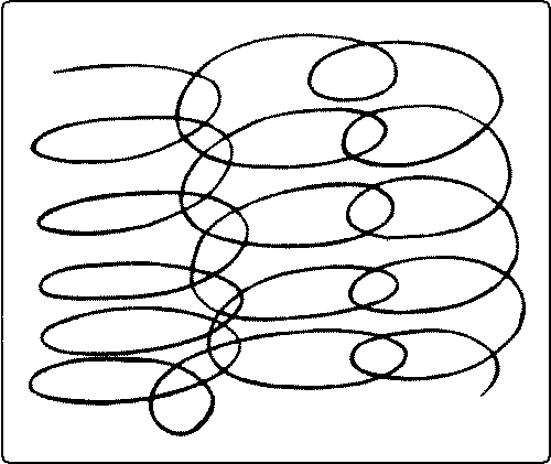
Another recipe for finishing. Use 4 drams grain alcohol, 2 drams orange shellac, 5 drams tincture of benzoin, 1 teaspoonful of olive oil. Dissolve and strain. Apply with pad in direction of grain.
Oil or Copal Varnishes. The old Cremona varnish once used for violins is supposed to have had amber (Greek, electron) as its base. It was a fossilized coniferous resin found on the shore of the Baltic Sea. The art of making it is said to be lost, probably because of the difficulty and danger of melting it, for this can be done only in oil on account of the danger of ignition. Hence its use has been abandoned.
Perhaps the most beautiful of all varnishes is lacquer, much used in China and Japan. It is made from the juice of the lacquer tree, (Rhus vernicifera) which is tapped during the summer months. The juice is strained and evaporated and then mixed with various substances, such as oil, fine clay, body pigment, and metallic dust, according to the ware for which it is intended. The manufacturing secrets are carefully guarded. The application of it is very difficult, the sap of young trees being used for first coats, and of old trees for the finishing coats. It must be dried in a damp, close atmosphere. For the best work ten or twelve coats are elaborately rubbed down and polished. Even the presence of it is very poisonous to some people and all workers in it are more or less affected.
The solvent or vehicle of the modern copal varnishes consists principally of linseed oil with some turpentine. Their base is Copal, a fossil, resinous substance of vegetable origin. The gums of which they are made have been chemically altered by long exposure in the earth. Other gums, as mastic, dammar, sandarac, and even resin are sometimes mixed with copal to cheapen the product or to cause more rapid drying. Copal is a generic name given originally to all fossil resins. Copals, as they are called, come from New Zealand, Mozambique, Zanzibar, West Africa, Brazil, and the Philippines. The best of the Copals is said to be the Kauri gum, originally exuded from the Kauri pine tree of New Zealand. The tree is still existent and [page 219] produces a soft, spongy sap, but the resin used in varnish is dug up from a few feet under ground in regions where there are now no trees. A commercially important copal and one noted for its hardness is the Zanzibar or East African Copal. It is found imbedded in the earth at a depth not greater than four feet over a wide belt of the mainland coast of Zanzibar, on tracts where not a single tree now grows. It occurs in lumps from the size of small pebbles to pieces weighing four or five pounds. The supply is said to be practically inexhaustible.
As to the manufacture of the Copal varnishes: first of all, a high grade oil is boiled at a high temperature, with different materials to oxidize it; for instance, red lead or oxide of manganese. The heat throws off the oxygen from the red lead or manganese. The oxygen is absorbed by the linseed oil, which is then put away to settle and age. When a batch of varnish is made, the gums are melted in a large kettle and then the requisite amount of oil is added and these carefully boiled together. This is removed from the fire and cooled down to a point, where turpentine can be added without volatilizing. These are thoroly mixed and then filtered under pressure and tanked and aged. The different grades of varnish depend upon the treatment of the oil, the proportion of oil and turpentine, the qualities of the gums, the aging, etc. Some by rubbing give a very high polish, some give a dull waxy finish, some are for out-of-door use, as Spar varnish and carriage varnish, some are for floors, some for furniture, some are high priced, some are cheap.
Process of Varnishing. The preliminary processes are the same as those for applying shellac, i. e., the surface of the wood must be perfectly even and smooth, and the staining, filling, and drying complete. Quick drying varnishes, like shellac, are applied, with but little on the brush. The heavy, high lustre varnishes, on the other hand, are applied with the brush full so that the varnish may even drip off the work. Then proceed as follows: Wipe off from the work the extra varnish with the brush and clean the brush on the edge of the cup. Repeat till the varnish is flowed over the work evenly. Be particularly careful, in that respect, of edges and corners. Set to dry in a dustless place. When dry and hard repeat the process from three to six times. Each coat must dry thoroly before the next coat is applied.
[page 220]Varnish polishing consists in rubbing off the varnish, not in rubbing it on, as in French polishing. To polish varnish, rub with a felt pad, powdered pumice-stone and water. Rub till the surface is smooth, unpitted and even, being careful not to rub thru the edges. Wipe clean with a wet sponge and chamois skin. This gives a dull or "egg-shell" finish. For polishing varnish, a simple method is to rub with a rotary motion, using a mixture of 1⁄2 sweet oil or cottonseed oil, and 1⁄2 alcohol.
A more laborious process is as follows: After rubbing to a dull finish, rub ground rotten stone and water with chamois skin in a circular motion. Let the rotten stone dry on the surface. Then wipe off with the naked hand, rubbing in a circular direction and wiping the hand every time after passing over the work. This looks simple, but is really a fine art. These processes have practically replaced French polishing in the trade.
Paints are used for the same purpose as other finishes, with the additional one of giving an opaque colored covering. The materials used are:
1. A body whose function is to give covering power. This is usually white lead, but it is often adulterated with zinc oxide; 2. Pigments; 3. Linseed oils, raw and boiled, which are used to give consistency, adhesiveness and also elasticity to the coat when dry. For outdoor work boiled oil is used and for indoor work, raw oil; 4. Turpentine, which is used to thin out the paint and to make it dry more quickly.
The common method of painting is: 1. Set any nails with nailset; 2. Sandpaper; 3. Shellac the knots; 4. Prime with a thin coat of paint, mostly white lead, (that is, little color,) boiled oil, and turpentine (the proportion of drying oil is greater than in ordinary paint); 5. Putty up cracks, nail holes, etc.; 6. Sandpaper if a small nice job; 7. Then paint two or three coats with paint thick enough so it will not run, with long, even strokes with the grain. The order of painting a door is, panels, muntins, rails, and last, stiles.
For inside work use half as much turpentine as oil. This gives a dull finish. For outside work, where lustre is wanted, little or no turpentine is used.
[page 221]This is the old way, and is still used for all common work. But for fine painting, as carriage work, a filler is now used first, because a priming to be durable should unite with the wood, grasping the fibers and filling the pores, so that after coats cannot sink in. The object is to cement the surface. Priming is often called "rough stuff." The old way did not do this, with the result that the oil separated from the lead and kept soaking into the wood. The principal makers of paints now recommend a filler before any white lead is added.
Brushes. It is well to have several varieties to help keep them distinct. For varnish and shellac, the best are those with the bristles set in hard rubber. For ordinary purposes, brushes one inch wide are satisfactory. For stains, cheap, tin-bound brushes are good enough, and are easily replaced.
Cups. Half-pint enameled steel cups are cheap, satisfactory, and easily kept clean. For the care of cups and brushes, see Chapter VI, The Equipment and Care of the Shop.
Steel wool. This consists of shavings, turned from thin steel discs set together in a lathe. It comes in various grades, No. 00 to No. 3. The finest, No. 00, is coarse enough for ordinary purposes.
Sandpaper. Use No. 00 smeared with boiled oil. Pulverized pumice stone and pulverized rotten stone, both very fine, are used to rub down inequalities and to give a dull finish to shellac or varnish. Use with oil on shellac and with oil or water on copal varnish. Horsehair and soft wood shavings are often used to rub down varnish. French felt, medium hard, is used for rubbing down copal varnish with pumice stone.
Cotton waste is the cheapest available material for wiping.
Cheese cloth is better for some purposes, but more expensive.
Soft cloth without lint is necessary for French polishing. "Berkeley muslin," "Old Glory," and "Lilly White" are trade names. A fine quality is necessary. The starch should be washed out and the cloth dried before using, and then torn into little pieces, say 4" square.
Fillers consist of silex or of ground earths mixed with oil, japan, and turpentine. Their object is to give a perfectly level and non-absorbent basis for varnish covering.
Oils. Raw linseed oil is very fat and dries slowly. It is used for interior work.
[page 222]Boiled oil is linseed oil boiled with litharge (PbO) and white vitriol, which removes much of the fatty ingredient and gives it drying quality.
Turpentine is a volatile oil from the sap of long-leaf pine. It is mixed with oil in painting to give further drying qualities.
Benzine is a cheap substitute for turpentine. It is a highly inflammable product of coal tar and evaporates quickly.
Drier is an oil in which resin has been dissolved. It is mixed with varnishes and paint to make them dry quickly. It is also sometimes used as a varnish itself.
Japan is a varnish-like liquid made of shellac or other resin, linseed oil, metallic oxides, and turpentine. It is used as a medium in which to grind colors and as a drier.
[page 223]References:*
(1) Stains.
Hodgson, II, pp. 25-59, 155-164.
Van Deusen, Man. Tr. Mag., 6: 93.
Maire, pp. 46-64.
(2) Fillers.
Hodgson, II, pp. 7-25.
Maire, 65-72.
(3) Oil Finish.
Hodgson, II, pp. 99-103.
Maire, p. 117.
(4) Wax.
Hodgson, II, pp. 93-99.
Maire, pp. 112-116.
(5) Varnish.
Shellac.
Maire, pp. 73-80, 101-111.
Journal, Soc. Arts, 49: 192.
Ency. Brit., Vol. XIV, "Lac."
Hodgson, II, pp. 66-93.
Inter. Encyc., Vol. X, "Lac."
Oil Varnish.
Hodgson, II, pp. 59-66.
Clark, pp. 1-69.
Maire, pp. 81-100.
Encyc. Brit., Vol. XXIV, "Varnish."
(6) Paints.
Brannt, p. 134-152.
Building Trades Pocketbook, pp. 357-360.
For detailed directions for the treatment of different woods, see Hodgson,
II, pp. 112-153, Maire, pp. 124-141.
* For general bibliography see p. 4.
[page 224]
A | B | C | D |
E | F | G | H |
I | J | K | L |
M | O | P |
R | S | T |
V | W | Y |
Transcriber's Note:There is no Fig. 19; and Fig. 47 had no caption—caption added from text.Some of the illustrations were on numbered pages which contained no text. Illustrations have been moved to more relevant places, and extraneous page numbers removed. Page number references from the Index, and from within the text, have been corrected where necessary. (sundry commas added to Bibliograpy, as needed for consistency.) ERRATA, and [sic]Page 13: 'thoroly' [sic] period spelling for 'thoroughly'.Page 16: 'If a horse fall ...' [sic] 'If a horse (should) fall ...' Page 47: 'eargerly' corrected to 'eagerly'. (They are eagerly sought after...). Page 47: 'chlorid' corrected to 'chloride'. (zinc chloride). Page 58: 'splinttering' corrected to 'splintering'. Page 63: 'especally' corrected to 'especially'. Page 90: 'varities' corrected to 'varieties'. Page 160: 'shouders' corrected to 'shoulders'. (Locate accurately with a knife point the shoulders...). Page 162: Replaced two gaps in text with 'wedges' and 'No. 34'. (No. 35. A wedged ... by driving the wedges into saw kerfs in the tenon instead of along its sides as in No. 34.) Page 189: 'Fig. 285, E' corrected to 'Fig. 285, C' (The cover may have cleats on its underside, Fig. 285, C, which fit just inside the box and keep the top in place.) Page 219: 'funiture' corrected to 'furniture'. (...some are for floors, some for furniture,...) |
***END OF THE PROJECT GUTENBERG EBOOK HANDWORK IN WOOD***
******* This file should be named 20846-h.txt or 20846-h.zip *******
This and all associated files of various formats will be found in:
http://www.gutenberg.org/2/0/8/4/20846
Updated editions will replace the previous one--the old editions will be renamed.
Creating the works from public domain print editions means that no one owns a United States copyright in these works, so the Foundation (and you!) can copy and distribute it in the United States without permission and without paying copyright royalties. Special rules, set forth in the General Terms of Use part of this license, apply to copying and distributing Project Gutenberg-tm electronic works to protect the PROJECT GUTENBERG-tm concept and trademark. Project Gutenberg is a registered trademark, and may not be used if you charge for the eBooks, unless you receive specific permission. If you do not charge anything for copies of this eBook, complying with the rules is very easy. You may use this eBook for nearly any purpose such as creation of derivative works, reports, performances and research. They may be modified and printed and given away--you may do practically ANYTHING with public domain eBooks. Redistribution is subject to the trademark license, especially commercial redistribution.
*** START: FULL LICENSE ***

THE FULL PROJECT GUTENBERG LICENSE
PLEASE READ THIS BEFORE YOU DISTRIBUTE OR USE THIS WORK

To protect the Project Gutenberg-tm mission of promoting the free
distribution of electronic works, by using or distributing this work
(or any other work associated in any way with the phrase "Project
Gutenberg"), you agree to comply with all the terms of the Full Project
Gutenberg-tm License (available with this file or online at
http://www.gutenberg.org/license).


Section 1.  General Terms of Use and Redistributing Project Gutenberg-tm
electronic works

1.A.  By reading or using any part of this Project Gutenberg-tm
electronic work, you indicate that you have read, understand, agree to
and accept all the terms of this license and intellectual property
(trademark/copyright) agreement.  If you do not agree to abide by all
the terms of this agreement, you must cease using and return or destroy
all copies of Project Gutenberg-tm electronic works in your possession.
If you paid a fee for obtaining a copy of or access to a Project
Gutenberg-tm electronic work and you do not agree to be bound by the
terms of this agreement, you may obtain a refund from the person or
entity to whom you paid the fee as set forth in paragraph 1.E.8.

1.B.  "Project Gutenberg" is a registered trademark.  It may only be
used on or associated in any way with an electronic work by people who
agree to be bound by the terms of this agreement.  There are a few
things that you can do with most Project Gutenberg-tm electronic works
even without complying with the full terms of this agreement.  See
paragraph 1.C below.  There are a lot of things you can do with Project
Gutenberg-tm electronic works if you follow the terms of this agreement
and help preserve free future access to Project Gutenberg-tm electronic
works.  See paragraph 1.E below.

1.C.  The Project Gutenberg Literary Archive Foundation ("the Foundation"
or PGLAF), owns a compilation copyright in the collection of Project
Gutenberg-tm electronic works.  Nearly all the individual works in the
collection are in the public domain in the United States.  If an
individual work is in the public domain in the United States and you are
located in the United States, we do not claim a right to prevent you from
copying, distributing, performing, displaying or creating derivative
works based on the work as long as all references to Project Gutenberg
are removed.  Of course, we hope that you will support the Project
Gutenberg-tm mission of promoting free access to electronic works by
freely sharing Project Gutenberg-tm works in compliance with the terms of
this agreement for keeping the Project Gutenberg-tm name associated with
the work.  You can easily comply with the terms of this agreement by
keeping this work in the same format with its attached full Project
Gutenberg-tm License when you share it without charge with others.

1.D.  The copyright laws of the place where you are located also govern
what you can do with this work.  Copyright laws in most countries are in
a constant state of change.  If you are outside the United States, check
the laws of your country in addition to the terms of this agreement
before downloading, copying, displaying, performing, distributing or
creating derivative works based on this work or any other Project
Gutenberg-tm work.  The Foundation makes no representations concerning
the copyright status of any work in any country outside the United
States.

1.E.  Unless you have removed all references to Project Gutenberg:

1.E.1.  The following sentence, with active links to, or other immediate
access to, the full Project Gutenberg-tm License must appear prominently
whenever any copy of a Project Gutenberg-tm work (any work on which the
phrase "Project Gutenberg" appears, or with which the phrase "Project
Gutenberg" is associated) is accessed, displayed, performed, viewed,
copied or distributed:

This eBook is for the use of anyone anywhere at no cost and with
almost no restrictions whatsoever.  You may copy it, give it away or
re-use it under the terms of the Project Gutenberg License included
with this eBook or online at www.gutenberg.org

1.E.2.  If an individual Project Gutenberg-tm electronic work is derived
from the public domain (does not contain a notice indicating that it is
posted with permission of the copyright holder), the work can be copied
and distributed to anyone in the United States without paying any fees
or charges.  If you are redistributing or providing access to a work
with the phrase "Project Gutenberg" associated with or appearing on the
work, you must comply either with the requirements of paragraphs 1.E.1
through 1.E.7 or obtain permission for the use of the work and the
Project Gutenberg-tm trademark as set forth in paragraphs 1.E.8 or
1.E.9.

1.E.3.  If an individual Project Gutenberg-tm electronic work is posted
with the permission of the copyright holder, your use and distribution
must comply with both paragraphs 1.E.1 through 1.E.7 and any additional
terms imposed by the copyright holder.  Additional terms will be linked
to the Project Gutenberg-tm License for all works posted with the
permission of the copyright holder found at the beginning of this work.

1.E.4.  Do not unlink or detach or remove the full Project Gutenberg-tm
License terms from this work, or any files containing a part of this
work or any other work associated with Project Gutenberg-tm.

1.E.5.  Do not copy, display, perform, distribute or redistribute this
electronic work, or any part of this electronic work, without
prominently displaying the sentence set forth in paragraph 1.E.1 with
active links or immediate access to the full terms of the Project
Gutenberg-tm License.

1.E.6.  You may convert to and distribute this work in any binary,
compressed, marked up, nonproprietary or proprietary form, including any
word processing or hypertext form.  However, if you provide access to or
distribute copies of a Project Gutenberg-tm work in a format other than
"Plain Vanilla ASCII" or other format used in the official version
posted on the official Project Gutenberg-tm web site (www.gutenberg.org),
you must, at no additional cost, fee or expense to the user, provide a
copy, a means of exporting a copy, or a means of obtaining a copy upon
request, of the work in its original "Plain Vanilla ASCII" or other
form.  Any alternate format must include the full Project Gutenberg-tm
License as specified in paragraph 1.E.1.

1.E.7.  Do not charge a fee for access to, viewing, displaying,
performing, copying or distributing any Project Gutenberg-tm works
unless you comply with paragraph 1.E.8 or 1.E.9.

1.E.8.  You may charge a reasonable fee for copies of or providing
access to or distributing Project Gutenberg-tm electronic works provided
that

- You pay a royalty fee of 20% of the gross profits you derive from
     the use of Project Gutenberg-tm works calculated using the method
     you already use to calculate your applicable taxes.  The fee is
     owed to the owner of the Project Gutenberg-tm trademark, but he
     has agreed to donate royalties under this paragraph to the
     Project Gutenberg Literary Archive Foundation.  Royalty payments
     must be paid within 60 days following each date on which you
     prepare (or are legally required to prepare) your periodic tax
     returns.  Royalty payments should be clearly marked as such and
     sent to the Project Gutenberg Literary Archive Foundation at the
     address specified in Section 4, "Information about donations to
     the Project Gutenberg Literary Archive Foundation."

- You provide a full refund of any money paid by a user who notifies
     you in writing (or by e-mail) within 30 days of receipt that s/he
     does not agree to the terms of the full Project Gutenberg-tm
     License.  You must require such a user to return or
     destroy all copies of the works possessed in a physical medium
     and discontinue all use of and all access to other copies of
     Project Gutenberg-tm works.

- You provide, in accordance with paragraph 1.F.3, a full refund of any
     money paid for a work or a replacement copy, if a defect in the
     electronic work is discovered and reported to you within 90 days
     of receipt of the work.

- You comply with all other terms of this agreement for free
     distribution of Project Gutenberg-tm works.

1.E.9.  If you wish to charge a fee or distribute a Project Gutenberg-tm
electronic work or group of works on different terms than are set
forth in this agreement, you must obtain permission in writing from
both the Project Gutenberg Literary Archive Foundation and Michael
Hart, the owner of the Project Gutenberg-tm trademark.  Contact the
Foundation as set forth in Section 3 below.

1.F.

1.F.1.  Project Gutenberg volunteers and employees expend considerable
effort to identify, do copyright research on, transcribe and proofread
public domain works in creating the Project Gutenberg-tm
collection.  Despite these efforts, Project Gutenberg-tm electronic
works, and the medium on which they may be stored, may contain
"Defects," such as, but not limited to, incomplete, inaccurate or
corrupt data, transcription errors, a copyright or other intellectual
property infringement, a defective or damaged disk or other medium, a
computer virus, or computer codes that damage or cannot be read by
your equipment.

1.F.2.  LIMITED WARRANTY, DISCLAIMER OF DAMAGES - Except for the "Right
of Replacement or Refund" described in paragraph 1.F.3, the Project
Gutenberg Literary Archive Foundation, the owner of the Project
Gutenberg-tm trademark, and any other party distributing a Project
Gutenberg-tm electronic work under this agreement, disclaim all
liability to you for damages, costs and expenses, including legal
fees.  YOU AGREE THAT YOU HAVE NO REMEDIES FOR NEGLIGENCE, STRICT
LIABILITY, BREACH OF WARRANTY OR BREACH OF CONTRACT EXCEPT THOSE
PROVIDED IN PARAGRAPH F3.  YOU AGREE THAT THE FOUNDATION, THE
TRADEMARK OWNER, AND ANY DISTRIBUTOR UNDER THIS AGREEMENT WILL NOT BE
LIABLE TO YOU FOR ACTUAL, DIRECT, INDIRECT, CONSEQUENTIAL, PUNITIVE OR
INCIDENTAL DAMAGES EVEN IF YOU GIVE NOTICE OF THE POSSIBILITY OF SUCH
DAMAGE.

1.F.3.  LIMITED RIGHT OF REPLACEMENT OR REFUND - If you discover a
defect in this electronic work within 90 days of receiving it, you can
receive a refund of the money (if any) you paid for it by sending a
written explanation to the person you received the work from.  If you
received the work on a physical medium, you must return the medium with
your written explanation.  The person or entity that provided you with
the defective work may elect to provide a replacement copy in lieu of a
refund.  If you received the work electronically, the person or entity
providing it to you may choose to give you a second opportunity to
receive the work electronically in lieu of a refund.  If the second copy
is also defective, you may demand a refund in writing without further
opportunities to fix the problem.

1.F.4.  Except for the limited right of replacement or refund set forth
in paragraph 1.F.3, this work is provided to you 'AS-IS,' WITH NO OTHER
WARRANTIES OF ANY KIND, EXPRESS OR IMPLIED, INCLUDING BUT NOT LIMITED TO
WARRANTIES OF MERCHANTIBILITY OR FITNESS FOR ANY PURPOSE.

1.F.5.  Some states do not allow disclaimers of certain implied
warranties or the exclusion or limitation of certain types of damages.
If any disclaimer or limitation set forth in this agreement violates the
law of the state applicable to this agreement, the agreement shall be
interpreted to make the maximum disclaimer or limitation permitted by
the applicable state law.  The invalidity or unenforceability of any
provision of this agreement shall not void the remaining provisions.

1.F.6.  INDEMNITY - You agree to indemnify and hold the Foundation, the
trademark owner, any agent or employee of the Foundation, anyone
providing copies of Project Gutenberg-tm electronic works in accordance
with this agreement, and any volunteers associated with the production,
promotion and distribution of Project Gutenberg-tm electronic works,
harmless from all liability, costs and expenses, including legal fees,
that arise directly or indirectly from any of the following which you do
or cause to occur: (a) distribution of this or any Project Gutenberg-tm
work, (b) alteration, modification, or additions or deletions to any
Project Gutenberg-tm work, and (c) any Defect you cause.


Section  2.  Information about the Mission of Project Gutenberg-tm

Project Gutenberg-tm is synonymous with the free distribution of
electronic works in formats readable by the widest variety of computers
including obsolete, old, middle-aged and new computers.  It exists
because of the efforts of hundreds of volunteers and donations from
people in all walks of life.

Volunteers and financial support to provide volunteers with the
assistance they need, is critical to reaching Project Gutenberg-tm's
goals and ensuring that the Project Gutenberg-tm collection will
remain freely available for generations to come.  In 2001, the Project
Gutenberg Literary Archive Foundation was created to provide a secure
and permanent future for Project Gutenberg-tm and future generations.
To learn more about the Project Gutenberg Literary Archive Foundation
and how your efforts and donations can help, see Sections 3 and 4
and the Foundation web page at http://www.gutenberg.org/fundraising/pglaf.


Section 3.  Information about the Project Gutenberg Literary Archive
Foundation

The Project Gutenberg Literary Archive Foundation is a non profit
501(c)(3) educational corporation organized under the laws of the
state of Mississippi and granted tax exempt status by the Internal
Revenue Service.  The Foundation's EIN or federal tax identification
number is 64-6221541.  Contributions to the Project Gutenberg
Literary Archive Foundation are tax deductible to the full extent
permitted by U.S. federal laws and your state's laws.

The Foundation's principal office is located at 4557 Melan Dr. S.
Fairbanks, AK, 99712., but its volunteers and employees are scattered
throughout numerous locations.  Its business office is located at
809 North 1500 West, Salt Lake City, UT 84116, (801) 596-1887, email
business@pglaf.org.  Email contact links and up to date contact
information can be found at the Foundation's web site and official
page at http://www.gutenberg.org/about/contact

For additional contact information:
     Dr. Gregory B. Newby
     Chief Executive and Director
     gbnewby@pglaf.org

Section 4.  Information about Donations to the Project Gutenberg
Literary Archive Foundation

Project Gutenberg-tm depends upon and cannot survive without wide
spread public support and donations to carry out its mission of
increasing the number of public domain and licensed works that can be
freely distributed in machine readable form accessible by the widest
array of equipment including outdated equipment.  Many small donations
($1 to $5,000) are particularly important to maintaining tax exempt
status with the IRS.

The Foundation is committed to complying with the laws regulating
charities and charitable donations in all 50 states of the United
States.  Compliance requirements are not uniform and it takes a
considerable effort, much paperwork and many fees to meet and keep up
with these requirements.  We do not solicit donations in locations
where we have not received written confirmation of compliance.  To
SEND DONATIONS or determine the status of compliance for any
particular state visit http://www.gutenberg.org/fundraising/pglaf

While we cannot and do not solicit contributions from states where we
have not met the solicitation requirements, we know of no prohibition
against accepting unsolicited donations from donors in such states who
approach us with offers to donate.

International donations are gratefully accepted, but we cannot make
any statements concerning tax treatment of donations received from
outside the United States.  U.S. laws alone swamp our small staff.

Please check the Project Gutenberg Web pages for current donation
methods and addresses.  Donations are accepted in a number of other
ways including checks, online payments and credit card donations.
To donate, please visit: http://www.gutenberg.org/fundraising/donate


Section 5.  General Information About Project Gutenberg-tm electronic
works.

Professor Michael S. Hart is the originator of the Project Gutenberg-tm
concept of a library of electronic works that could be freely shared
with anyone.  For thirty years, he produced and distributed Project
Gutenberg-tm eBooks with only a loose network of volunteer support.

Project Gutenberg-tm eBooks are often created from several printed
editions, all of which are confirmed as Public Domain in the U.S.
unless a copyright notice is included.  Thus, we do not necessarily
keep eBooks in compliance with any particular paper edition.

Each eBook is in a subdirectory of the same number as the eBook's
eBook number, often in several formats including plain vanilla ASCII,
compressed (zipped), HTML and others.

Corrected EDITIONS of our eBooks replace the old file and take over
the old filename and etext number.  The replaced older file is renamed.
VERSIONS based on separate sources are treated as new eBooks receiving
new filenames and etext numbers.

Most people start at our Web site which has the main PG search facility:

http://www.gutenberg.org

This Web site includes information about Project Gutenberg-tm,
including how to make donations to the Project Gutenberg Literary
Archive Foundation, how to help produce our new eBooks, and how to
subscribe to our email newsletter to hear about new eBooks.

EBooks posted prior to November 2003, with eBook numbers BELOW #10000,
are filed in directories based on their release date.  If you want to
download any of these eBooks directly, rather than using the regular
search system you may utilize the following addresses and just
download by the etext year.

http://www.gutenberg.org/dirs/etext06/

    (Or /etext 05, 04, 03, 02, 01, 00, 99,
     98, 97, 96, 95, 94, 93, 92, 92, 91 or 90)

EBooks posted since November 2003, with etext numbers OVER #10000, are
filed in a different way.  The year of a release date is no longer part
of the directory path.  The path is based on the etext number (which is
identical to the filename).  The path to the file is made up of single
digits corresponding to all but the last digit in the filename.  For
example an eBook of filename 10234 would be found at:

http://www.gutenberg.org/dirs/1/0/2/3/10234

or filename 24689 would be found at:
http://www.gutenberg.org/dirs/2/4/6/8/24689

An alternative method of locating eBooks:
http://www.gutenberg.org/dirs/GUTINDEX.ALL

*** END: FULL LICENSE ***